
Related Manuals for Stryker 1069


Summary of Contents for Stryker 1069
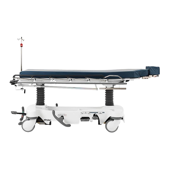
- Page 1 Head/Neck Surgery Series 1069 Head/Neck Surgery Stretcher Maintenance Manual For stretchers with serial numbers of 9901034660 and above For Parts or Technical Assistance 800–327–0770...
- Page 2 INTRODUCTION AND SET–UP INFORMATION Introduction ................1–1 Specifications .
- Page 3 LITTER MAINTENANCE Siderail Latch Adjustment ............. . . 4–2 Arm Board Counterbalance Adjustment .
-
Page 4: Table Of Contents
ASSEMBLY DRAWINGS AND PARTS LISTS (CONTINUED) Optional Dual Lowering Pedal Assembly ..........6–31 Base Labeling Assembly . - Page 5 ASSEMBLY DRAWINGS AND PARTS LISTS (CONTINUED) Standard, Removable I.V. Pole Assembly ..........6–90 Optional 2–Stage I.V.
- Page 6 This quick reference guide will help you locate the section of the manual you need to service your equipment or to order parts for it. Find the black tab matching the section you are looking for and match it with the corresponding tabs that mark the section in the body of the manual.
-
Page 8: Introduction
INTRODUCTION This manual is designed to assist you with the maintenance of the 1069 Head/Neck Surgery Bed. Read it thoroughly before beginning any maintenance on the equipment. SPECIFICATIONS Maximum Weight Capacity 500 pounds Overall Bed Length/Width 88”/31.5” Minimum/Maximum Bed Height 22.5”/36”... - Page 9 If requested by Stryker, products or parts for which a warranty claim is made shall be returned prepaid to Stryker’s factory. Any improper use or any alteration or repair by others in such manner as in Stryker’s judgement affects the product materially and adversely shall...
- Page 10 Stryker will perform all service during regular business hours (9–5) * Replacement parts and labor for products under PM contract will be discounted. ** Does not include any disposable items, I.V. poles (except for Stryker HD permanent poles), mattresses, or damage re- sulting from abuse.
-
Page 12: Cleaning
GENERAL INFORMATION This section contains cleaning instructions and a checklist to assist with the routine preventive maintenance and cleaning of your equipment. In the text, the words “right” and “left” refer to the right and left sides of a patient lying face up on the bed. PREVENTIVE MAINTENANCE CONTENTS Cleaning . - Page 13 If these types of products are used to clean Stryker patient handling equipment, measures must be taken to insure the stretchers are rinsed with clean water and thoroughly dried following cleaning. Failure to properly rinse and dry the stretchers will leave a cor- rosive residue on the surface of the stretcher, possibly causing premature corrosion of critical components.
-
Page 14: Preventive Maintenance Checklist
Preventative maintenance should be performed at a minimum of annually. A preventative maintenance pro- gram should be established for all Stryker Medical equipment. Preventative maintenance may need to be performed more frequently based on the usage level of the product. - Page 16 GENERAL INFORMATION This section contains tool lists and step–by–step procedures to assist with the maintenance and servicing of the base portion of your equipment. In the text, the words “right” and “left” refer to the right and left sides of a patient lying face up on the bed. BASE MAINTENANCE CONTENTS Caster Assembly Replacement .
-
Page 17: Caster Assembly Replacement
Caster Assembly Replacement 1. Remove the old caster assembly. 2. Install the replacement caster and caster nut. Tighten the caster nut to 90–105 ft.–lb. with a torque wrench. NOTE A new caster assembly with a 3M patch does not require the application of Loctite at assembly. However, the patch is appropriate for only one installation. -
Page 18: Caster Cover Installation And Removal
Caster Cover Installation and Removal Looking through the larger of the two side cut–outs, align cover with axle nut or bolt head, as shown. Double Prongs Push down on the opposite side of the cover until single prong engages with caster horn. Single Prong Top View (Cut–Away) Properly Attached... -
Page 19: Brake Cam Replacement
Brake Cam Replacement Brake Cam Part Number 715–201–213 Required Tools: Phillips Screwdriver String or Bungee Cord 3/32” Allen Wrench 1/8” Allen Wrench Procedure: 1. Remove the four Phillips screws holding the base hood to the frame. Lift and support the base hood using string or bungee cord. -
Page 20: Brake Adjustment
Brake Adjustment Required Tools: 3/32” Hex Allen Wrench Pry Bar Thread ”Locktite” Flat on thread of stud must always be aligned with the set screw. Turn must always be full circle only. Base Side Control Pedal Linkage Adjustment Required Tools: 3/8”... -
Page 21: Base Side Control Brake/Steer Gear Replacement
Base Side Control Brake/Steer Gear Replacement Required Tools: Pliers String or Bungee Cord Floor Jack or Equivalent 1/8” Allen Wrench 5/32” Allen Wrench 3/8” Box End Wrench (2) 9/16” Box End Wrenches 3/16” Punch 1/4” Punch Hammer Procedure: 1. Apply the stretcher brakes. 2. -
Page 22: Jack Replacement
Jack Replacement (Without Compression Spring) Required Tools: 3/8” Wrench 1/2” Socket 1/2” Wrench Needle–Nosed Pliers Replacement Procedure: 1. Apply stretcher brakes. Raise litter to full up. Raise Fowler to full up and raise siderails. 2. Use a 3/8” wrench to remove the bolt in the litter support tube above black bellows on both ends. 3. -
Page 23: Jack Assembly Torque Specification
Remove the excess air (vacuum) in the hydraulic sys- rod may or may not move. tem (see below). Contact Stryker technical service at 1–800–327–0770 for further assistance. Removing Excess Air (Vacuum) from the Hydraulic System Procedure: 1. Verify all hydraulic linkages are secure and operating properly (see page 3–5). -
Page 24: Checking Hydraulic Fluid Level
6. The hydraulic fluid should be visible at the bottom of the fill hole. If it is not, add Mobil Aero HFA hydraulic fluid (Stryker part number 2020–70–475) until the fluid is visible at the bottom of the fill hole. Replace the fill plug. -
Page 25: Constant Flow Jack Descent Rate Adjustment
Constant Flow Jack Descent Rate Adjustment Required Tools: Bungee Cords Adjustment Procedure: 1. Pump the litter up to full height 2. Lift the base hood, separating the Velcro holding it to the base frame. 3. The adjustable descent valve is located on the base of the jack and has a blue knob on the end. To adjust, loosen the silver locking ring by turning it counterclockwise. -
Page 26: Hydraulic Jack Valve Replacement
Hydraulic Jack Valve Replacement Required Tools: 3/8 Open End Wrench Stiff Wire (with bent, pointed end) Small Needle Nose Pliers 3/4 Open End Wrench Torque Wrench (with Ft. Lbs. adjust.) 7/32 Hex Allen Wrench 1/2 Inch Diameter Rod Replacement of Check Valve WARNING To avoid personal injury or damage to the stretcher, remove the litter and the base hood before beginning service on the jacks. - Page 27 Hydraulic Jack Valve Replacement (Continued) Replacement of Release Valve WARNING To avoid personal injury or damage to the stretcher, remove the litter and the base hood before beginning service on the jacks. Lower the jack rod completely to relieve the pressure on the pump piston side of the jack.
-
Page 28: Base Lubrication
Base Lubrication page 3–13... - Page 30 GENERAL INFORMATION This section contains tool lists and step–by–step procedures to assist with the maintenance and servicing of the litter portion of your equipment. In the text, the words “right” and “left” refer to the right and left sides of a patient lying face up on the bed. LITTER MAINTENANCE CONTENTS Siderail Latch Adjustment .
-
Page 31: Siderail Latch Adjustment
Siderail Latch Adjustment Required Tools: 1/8” Hex Allen Wrench WARNING The siderail latch adjustment is pre–set at the factory, and there should not normally be a need for readjust- ment. If adjustment must be done it is important to follow the procedure below. If it is not done properly, injury to the patient or user could occur. -
Page 32: Pneumatic Fowler Adjustment
Pneumatic Fowler Adjustment Required Tools: (2) 3/8” Open End Wrenches Adjustment Procedure: 1. Apply the stretcher brakes. 2. Pump the stretcher litter up to full height. 3. Move the Fowler to 70_ or higher. 4. Using (2) 3/8” wrenches, loosen the two nuts (A) on the adjustment screw (B). If the Fowler is not holding its position, turn the adjustment screw up, away from the release pin on the pneumatic cylinder (C). -
Page 33: Pneumatic Fowler Release Handle Adjustment
Pneumatic Fowler Release Handle Adjustment Required Tools: #2 Phillips Screwdriver Adjustment Procedure: 1. Apply the stretcher brakes. 2. Loosen the two Phillips head screws on the handle linkage. Release the handle tension spring on the patient’s left side. 3. Adjust the handles so there is a 3/4” gap between the inner Fowler frame and the handle. 4. -
Page 34: Pneumatic Cylinder Replacement
Pneumatic Cylinder Replacement Required Tools: (2) 17 mm. Wrenches 11/16” Open End Wrench 5/16” Hex Allen Wrench Adjustment Procedure: 1. Apply the stretcher brakes. 2. Pump the litter up to full height. 3. Move the Fowler to 70_. 4. Using two 17 mm. wrenches, remove both the large nuts (A) from the top of the pneumatic cylinder. 5. -
Page 35: Articulating Head Piece Adjustment
Articulating Head Piece Adjustment Required Tools: #2 Phillips Screwdriver 7/16” Socket and Ratchet Standard Screwdriver Adjustment Procedure: 1. If the neck section is binding, the (patient) left handle needs adjustment. If the head section is binding, the (patient) right handle needs adjustment. If you are adjusting the neck section handle, the 4 Phillips head screws (A) holding the neck section cover (B) must be removed. - Page 36 ........1069–70 Caster Cover Kit .
- Page 37 Pads, Pre–Op/Post–Op Head Piece, 2” ......1069–62 Pads, Pre–Op/Post–Op Head Piece, 3”...
- Page 38 GENERAL INFORMATION This section contains assembly drawings and parts lists to assist with the identification of individual compo- nents of the equipment and accessories. In the parts lists, the words “right” and “left” refer to the right and left sides of a patient lying face up on the bed.
- Page 39 ASSEMBLY DRAWINGS AND PARTS LISTS CONTENTS (CONTINUED) Fowler Crankscrew Assembly ............6–69 Dual Articulating Head Piece Assembly .
- Page 40 Side Control Base Assembly page 6–3...
- Page 41 Side Control Base Assembly page 6–4...
- Page 42 Side Control Base Assembly HEAD END Assembly part number 1068–1–210 (reference only) FOOT END page 6–5...
- Page 43 Side Control Base Assembly Item Part No. Part Name Qty. Item Part No. Part Name Qty. 715–1–11 Brake Cushion 3–62 Hex Hd. Cap Screw 715–1–61 Caster Brake Weldment 3–85 Hex Hd. Cap Screw 715–1–92 Pump Pedal Shaft 4–146 Soc. Hd. Cap Screw 715–201–94 Compression Spring 8–17...
- Page 44 End Control Base Assembly page 6–7...
- Page 45 End Control Base Assembly page 6–8...
- Page 46 End Control Base Assembly page 6–9...
- Page 47 End Control Base Assembly Item Part No. Part Name Qty. Item Part No. Part Name Qty. 715–1–11 Brake Cushion 3–4 Hex Hd. Cap Screw 715–1–61 Caster Brake Weldment 3–62 Hex Hd. Cap Screw 715–201–94 Compression Spring 3–85 Hex Hd. Cap Screw 715–1–133 Collar 8–17...
- Page 48 715–201–150 Brake Adjuster Assembly Item Part No. Part Name Qty. 715–1–180 Cam Bearing 715–201–62 Threaded Stud Assembly 14–4 Nylon Washer 28–8 External Retaining Ring page 6–11...
- Page 49 715–201–213 Brake Cam Assembly Item Part No. Part Name Qty. 16–59 Hex Nut 8–21 Soc. Hd. Shoulder Screw 715–201–173 Brake Connecting Link 715–301–221 Brake Cam page 6–12...
-
Page 50: Side Control Pump Pedal Assembly
Side Control Pump Pedal Assembly Item Part No. Part Name Qty. 81–44 Bronze Bearing 715–201–126 Slip–On Pedal Pad 715–201–83 Pump Pedal Weldment 26–143 Groove Pin page 6–13... - Page 51 716–201–288 Foot End Pump Pedal Assembly Item Part No. Part Name Qty. 26–145 Spring Pin 716–201–14 Foot End Pump Rod 716–1–283 Pump Pivot Housing 715–201–126 Pedal 1210–201–551 Eye Bolt 16–14 Nylock Nut 26–261 Groove Pin page 6–14...
-
Page 52: Head End Pump Pedal Assembly
716–201–292 Head End Pump Pedal Assembly Item Part No. Part Name Qty. 26–145 Spring Pin 716–1–285 Pump Pivot Housing, Hd. End 716–201–14 Head End Pump Rod 715–201–126 Pedal 1210–201–551 Eye Bolt 16–14 Nylock Nut 26–261 Groove Pin page 6–15... - Page 53 1069–70 Optional Removable Brake/Steer Pedal Assembly Assembly part number 1069–70–10 (reference only) Item Part No. Part Name Qty. 4–160 Socket Hd. Cap Screw 16–3 Fiberlock Nut 26–143 Groove Pin 1210–201–153 Butterfly “V” Pedal 1068–300–000 Removable Pedal Adapter page 6–15.1...
- Page 54 Notes page 6–15.2...
-
Page 55: Jack Assembly
1231–70–10 Jack Assembly Item Part No. Part Name Qty. Item Part No. Part Name Qty. 388–100–38 Plug 715–1–325 Actuator Rod 390–1–238 Actuator Gasket (page 6–17) Jack Base Ass’y 390–1–243 Gasket 926–20–161 Parker Packing 390–1–244 Base Gasket 926–20–162 Wear Ring 390–2–139 Retaining Ring 4–14 Soc. -
Page 56: Jack Base Assembly
Jack Base Assembly Assembly part number 1231–70–5 (reference only) Item Part No. Part Name Qty. Item Part No. Part Name Qty. 48–147 Base Plug 926–20–153 Check Valve 390–2–134 Conical Comp. Spring 926–20–154 Seal 715–1–307 Needle Valve 1210–170–13 Base Plug 715–1–309 Valve Plug 1210–270–12 Jack Base 715–1–329... -
Page 57: Constant Flow Jack Assembly
1231–70–210 Constant Flow Jack Assembly Item Part No. Part Name Qty. Item Part No. Part Name Qty. 388–100–38 Plug 926–20–161 Parker Packing 390–1–238 Actuator Gasket 926–20–162 Wear Ring 390–1–243 Gasket (page 6–19) Jack Base Ass’y 390–1–244 Base Gasket 4–14 Soc. Hd. Cap Screw 390–2–139 Retaining Ring 45–14... -
Page 58: Constant Flow Jack Base Assembly
Constant Flow Jack Base Assembly Assembly part number 5050–370–100 (reference only) Item Part No. Part Name Qty. Item Part No, Part Name Qty. 38–311 Compression Spring 715–1–341 Poppet 45–6 O–Ring 715–270–1 45–966 O–Ring 926–20–153 Check Valve 45–967 O–Ring 926–20–154 Seal 390–2–134 Conical Comp. -
Page 59: 715-100-425 Jack Pump Piston Assembly
715–100–425 Jack Pump Piston Assembly Assembly part number 715–201–325 (reference only) Item Part No. Part Name Qty. 715–1–328 Piston Wear Ring 715–1–400 O–Ring Back Up 715–200–316 Pump Cylinder 715–201–318 Pump Piston 715–201–327 Cylinder Wear Ring 14–50 Bearing Retainer 45–110 O–Ring 715–1–329 Pump Seal (not shown) page 6–20... -
Page 60: Base Assembly With Steerlock Caster Option
Base Assembly with Steerlock Caster Option Assembly part number 1000–159 (reference only) HEAD END Item Part No. Part Name Qty. (page 6–22) Steer Caster Assembly (page 6–23) Caster Assembly 1000–210–62 Steer Lock Linkage Bar 8–21 Shoulder Bolt 14–2 Washer 38–211 Spring page 6–21... -
Page 61: 715-269-100 Caster Assembly With Steerlock
715–269–100 Caster Assembly with Steerlock Assembly part number 715–2–21 (reference only) Item Part No. Part Name Qty. 700–10–50 Steer Lock Caster Weldment 715–2–25 Caster Wheel 16–60 Hex Nut 3–99 Hex Bolt 715–3–96 Hex Bolt 1000–59–10 Latch Assembly 11–310 Flat Washer page 6–22... -
Page 62: Standard Caster Assembly
Standard Caster Assembly Item Part No. Part Name Qty. 3–99 Hex Hd. Cap Screw 11–310 Washer 16–60 Hex Nut 715–2–16 Horn Assembly 715–3–96 Hex Hd. Cap Screw 715–1–265 Wheel Cover, Right 715–1–266 Wheel Cover, Left 715–2–25 Wheel 715–1–158 Caster Nut (not shown) p/n 715–259–400 –... -
Page 63: Pivot Rod Assembly
1010–260 Optional Fifth Wheel Assembly FOOT END HEAD END Item Part No. Part Name Qty. 14–79 Nylon Washer 11–13 Washer 27–16 Cotter Pin (page 6–25) Pivot Rod Assembly 1210–1–145 1210–1–148 Torsion Spring 1210–201–149 Spring Spacer 4–10 Bolt (page 6–26) Wheel Arm Assembly 1210–1–146 Torsion Spring 26–35... -
Page 64: Pivot Rod Assembly
Fifth Wheel Pivot Rod Assembly Assembly part number 1210–201–2 (reference only) Item Part No. Part Name Qty. 1210–1–143 Pivot Rod 14–79 Nylon Washer 1210–1–144 Roller 28–131 Snap Ring 27–16 Cotter Pin page 6–25... -
Page 65: 715-201-125 Fifth Wheel Arm Assembly
715–201–125 Fifth Wheel Arm Assembly Item Part No. Part Name Qty. 1210–201–553 Wheel Arm 1210–1–147 Fifth Wheel 3–31 Hex Hd. Cap Screw 16–35 Nylock Nut page 6–26... - Page 66 page 6–27...
-
Page 67: Optional Side Control Brake Assembly
Optional Side Control Brake Assembly page 6–28... - Page 68 Optional Side Control Brake Assembly Item Part No. Part Name Qty. 1210–301–400 Gear Box Weldment 1210–301–412 Support 1210–201–409 Side Control Brake/Steer Rod 1210–201–407 1210–301–406 Spacer 1210–301–405 Miter/Spur Gear 1210–301–404 Spur Gear 1210–301–403 Miter Gear 1210–201–401 Flange Bearing 1210–201–336 Steer Label 1210–201–335 Brake Label 1210–201–153...
-
Page 69: Optional Uni-Lower Pedal Assembly
Optional Uni–Lower Pedal Assembly Assembly part number 1210–500 (reference only) FOOT END HEAD END Item Part No. Part Name Qty. 715–201–127 Uni–Lowering Pedal 715–1–333 Release Rod Stop Sleeve 25–50 Pop Rivet page 6–30... -
Page 70: Optional Dual Lowering Pedal Assembly
Optional Dual Lowering Pedal Assembly Assembly part number 1210–501 (reference only) FOOT END HEAD END Item Part No. Part Name Qty. 715–201–126 Pump Pedal 26–143 Groove Pin page 6–31... - Page 71 1001–200–2 Base Hood 715–1–134 Bellows 1210–201–335 Red Brake Label 1210–201–336 Green Steer Label 946–201–60 Stryker Logo Label Color Item A Control Item B Control Item C Control Item D Control Litter Bumper Set P/N Label, Head End Label, Foot End...
- Page 72 Same Day Surgery 1010–900–275 Cardio. 1010–900–280 Ultrasound 1010–900–285 NOTE All base hood department labels are quantity of two. FOOT BOARD DEPARTMENT LABELS Department Label Part No. Demo Stryker 1010–900–186 Ophthalmology 1010–900–187 Outpatient Surgery 1010–900–188 Recovery 1010–900–189 Trauma 1010–900–190 Urgence 1010–900–191 Special (Blank) 1010–900–192...
- Page 73 Red Brake Label 1210–201–336 Green Steer Label 1210–201–337 Head Down Label, Foot End 1210–201–338 Foot Down Label, Foot End 946–201–6 Stryker Logo Label Color Item A Control Item B Control Item C Side Control Litter Bumper Strip Set P/N Label, Head End...
- Page 74 Litter Assembly page 6–35...
-
Page 75: Litter Assembly
Litter Assembly HEAD END page 6–36... - Page 76 1010–1–17 Roller Plate 1010–32–66 Rectangular Hole Plug (page 6–38) Foot End Jack Support Ass’y 1068–20–38 Bumper Channel (page 6–39) Head End Jack Support Ass’y 1069–30–50 Litter Frame Weldment 11–14 Washer 16–28 Hex Nut 25–38 Blind Rivet 26–57 Spring Pin 28–23 External Retaining Ring 3–47...
-
Page 77: Foot End Jack Support Assembly
Foot End Jack Support Assembly Assembly part number 1010–32–110 (reference only) Item Part No. Part Name Qty. 1010–32–85 Support Tube Assembly 46–1 Sq. Hd. Set Screw 938–1–401 Collar Assembly 16–11 Flexlock Nut 1010–32–108 Roller Assembly 1010–32–64 Carrier Tube, Std. 919–30–28 Rack Guide 44–29 Double–Sided Foam Tape... -
Page 78: Head End Jack Support Assembly
Head End Jack Support Assembly Assembly part number 1069–30–30 (reference only) Item Part No. Part Name Qty. 721–32–160 Support Tube Assembly 938–1–401 Collar 1069–30–20 Jack Mount Weldment, Left 1069–30–25 Jack Mount Weldment, Right 46–1 Sq. Hd. Set Screw page 6–39... - Page 79 page 6–40...
- Page 80 1069–32–20 Zero Articulating Pneumatic Fowler Assembly LEFT PIVOT BRACKET ASSEMBLY RIGHT PIVOT BRACKET ASSEMBLY page 6–41...
- Page 81 1069–32–20 Zero Articulating Pneumatic Fowler Assembly Right Handle Sub–assembly Left Handle Sub–assembly page 6–42...
- Page 82 1069–32–20 Zero Articulating Pneumatic Fowler Assembly Spring Attachment – Both Sides page 6–43...
- Page 83 1069–32–20 Zero Articulating Pneumatic Fowler Assembly Cylinder Assembly – Both Sides page 6–44...
- Page 84 1069–32–20 Zero Articulating Pneumatic Fowler Assembly Item Part No. Part Name Qty. Item Part No. Part Name Qty. 1069–31–11 Rivet 14–87 Nylon Flat Washer 1069–31–41 Handle Pivot Bracket, Lt. 11–180 Steel Flat Washer 1210–31–103 “L” Bracket 16–28 Nylock Nut 1069–31–46 Handle Pivot Bracket, Rt.
- Page 85 1069–32–15 Optional Single Articulating Pneumatic Fowler Ass’y LEFT PIVOT BRACKET ASSEMBLY RIGHT PIVOT BRACKET ASSEMBLY page 6–46...
- Page 86 1069–32–15 Optional Single Articulating Pneumatic Fowler Ass’y Left Handle Assembly Right Handle Assembly page 6–47...
- Page 87 1069–32–15 Optional Single Articulating Pneumatic Fowler Ass’y page 6–48...
- Page 88 1069–32–15 Optional Single Articulating Pneumatic Fowler Ass’y page 6–49...
- Page 89 1069–32–15 Optional Single Articulating Pneumatic Fowler Ass’y Cylinder Assembly – Both Sides Item Part No. Part Name Qty. 1069–31–11 Rivet 1069–31–41 Handle Pivot Bracket, Left 1210–31–103 “L” Bracket 1069–31–46 Handle Pivot Bracket, Right 1069–31–75 Handle Weldment, Right 5050–531–200 Red Handle Cover 1069–31–31...
- Page 90 1069–32–15 Optional Single Articulating Pneumatic Fowler Ass’y Item Part No. Part Name Qty. 1069–32–75 Fowler Skin 25–50 Pop Rivet 7–42 Truss Hd. Screw 1069–32–70 Fowler Weldment 1069–31–12 Barrel Nut 7–62 Truss Hd. Screw 3001–300–99 Fowler Pivot Bushing 14–87 Nylon Flat Washer 11–180...
- Page 91 1069–32–10 Optional Dual Articulating Pneumatic Fowler Ass’y LEFT PIVOT BRACKET ASSEMBLY RIGHT PIVOT BRACKET ASSEMBLY page 6–52...
- Page 92 1069–32–10 Optional Dual Articulating Pneumatic Fowler Ass’y Left Handle Assembly Right Handle Assembly page 6–53...
- Page 93 1069–32–10 Optional Dual Articulating Pneumatic Fowler Ass’y page 6–54...
- Page 94 1069–32–10 Optional Dual Articulating Pneumatic Fowler Ass’y page 6–55...
- Page 95 1069–32–10 Optional Dual Articulating Pneumatic Fowler Ass’y CYLINDER ASSEMBLY – BOTH SIDES page 6–56...
- Page 96 1069–32–10 Optional Dual Articulating Pneumatic Fowler Ass’y Item Part No. Part Name Qty. 1069–31–11 Rivet 1069–31–41 Handle Pivot Bracket, Left 1210–31–103 “L” Bracket 1069–31–46 Handle Pivot Bracket, Right 1069–31–65 Handle Weldment, Right 1069–31–200 Red Handle Cover 1069–31–31 Short Handle Adjustment Link 7–50...
- Page 97 1069–42–60 Optional Zero Articulating Crank Fowler Assembly page 6–58...
- Page 98 1069–42–60 Optional Zero Articulating Crank Fowler Assembly Item Part No. Part Name Qty. 1069–32–65 Fowler Skin 7900–1–102 Velcro Pile 25–50 Pop Rivet 7–42 Truss Hd. Screw 1069–32–60 Fowler Weldment 1069–31–12 Barrel Nut 4–54 Button Hd. Screw 16–11 Nylock Nut 1069–31–13 Hole Plug 11–17...
- Page 99 1069–42–55 Optional Single Articulating Crank Fowler Assembly page 6–60...
- Page 100 1069–42–55 Optional Single Articulating Crank Fowler Assembly page 6–61...
- Page 101 1069–42–55 Optional Single Articulating Crank Fowler Assembly Item Part No. Part Name Qty. Item Part No. Part Name Qty. 1069–32–75 Fowler Skin 966–70–36 Spacer 25–50 Pop Rivet 3–20 Hex Hd. Cap Screw 7–42 Truss Hd. Screw 966–70–27 Bar Clamp 1069–32–70 Fowler Weldment 21–73...
- Page 103 1069–42–50 Optional Dual Articulating Crank Fowler Assembly page 6–64...
- Page 104 1069–42–50 Optional Dual Articulating Crank Fowler Assembly page 6–65...
- Page 105 1069–42–50 Optional Dual Articulating Crank Fowler Assembly page 6–66...
- Page 106 1069–42–50 Optional Dual Articulating Crank Fowler Assembly Item Part No. Part Name Qty. 1069–32–55 Fowler Skin 25–50 Pop Rivet 7–42 Truss Hd. Screw 1069–32–50 Fowler Weldment 1069–31–12 Barrel Nut (page 6–70) Head Piece Assembly 1069–33–93 Head Pivot Shaft 52–17 Nylon Flat Washer 4–74...
-
Page 107: Crank Fowler Assembly
Optional Crank Fowler Assembly Assembly part number 1069–42–20 (reference only) Item Part No. Part Name Qty. 3–78 Hex Hd. Cap Screw 8–27 Shoulder Bolt 11–3 Flat Washer 16–28 Nylock Nut 946–1–64 Fowler Symbol Label 1010–34–15 Mounting Bracket Ass’y 1066–33–68 Sleeve (page 6–69) -
Page 108: Fowler Crankscrew Assembly
1069–42–10 Optional Fowler Crankscrew Assembly DETAIL A Item Part No. Part Name Qty. 1069–42–23 Crank Arm Link 1550–1–16 Crank Handle 946–33–18 Crank Disc 938–1–177 Knob 16–5 Conelock Nut 378–24–29 Shoulder Bolt 946–33–35 Fowler Screw 26–14 Roll Pin 81–174 Thrust Washer 938–1–175... - Page 109 1069–33–10 Optional Dual Articulating Head Piece Assembly Neck Toggle/Gear Assembly page 6–70...
- Page 110 1069–33–10 Optional Dual Articulating Head Piece Assembly Head Toggle/Gear Assembly page 6–71...
- Page 111 1069–33–10 Optional Dual Articulating Head Piece Assembly page 6–72...
- Page 112 1069–33–10 Optional Dual Articulating Head Piece Assembly BOTTOM VIEW OF ASSEMBLY Item Part No. Part Name Qty. 1068–234–36 Head Piece Handle Grip 1069–33–30 Neck Section Weldment 1069–33–40 Head Section Weldment 1069–33–60 Handle Weldment, Left 1069–33–65 Handle Weldment, Right 1069–33–70 Anti–Rotation Gear 1069–33–75...
-
Page 113: Stationary Foot Section Assembly
Stationary Foot Section Assembly Assembly part number 1068–44–10 (reference only) Item Part No. Part Name Qty. 3–73 Hex Hd. Cap Screw 14–3 Washer 16–28 Nylock Hex Nut 25–101 Rivet 1010–32–60 Pivot Bolt 1068–44–44 Stationary Foot Skin 1068–44–50 Stationary Foot Weldment 381–24–7 Velcro Adhesive Pile page 6–74... -
Page 114: Knee Gatch Assembly
Optional Knee Gatch Assembly Assembly part number 1068–40–10 (reference only) P/N 1068–30–50 Litter Frame Weldment (Ref.) Item Part No. Part Name Qty. Item Part No, Part Name Qty. 721–31–65 Hole Plug 1510–34–90 Slider Pad (page 6–76) Foot/Thigh Subassembly 1510–34–94 Calf Stand Rest 16–28 Nylock Hex Nut 1010–34–15... -
Page 115: Foot And Thigh Section Assembly
Optional Knee Gatch Foot and Thigh Section Assembly Assembly part number 1068–41–10 (reference only) Item Part No. Part Name Qty. 7900–1–102 Velcro Adhesive Pile 1.92’ 14–3 Washer 14–21 Nylon Washer 16–28 Nylock Hex Nut 25–79 Rivet 25–101 Rivet 27–7 Cotter Pin 1010–32–60 Pivot Bolt 1010–34–23... -
Page 116: Knee Gatch Crankscrew Assembly
1068–46–10 Optional Knee Gatch Crankscrew Assembly Item Part No. Part Name Qty. 946–33–18 Crank Disk 1550–1–16 Crank Handle 26–45 Roll Pin 26–14 Roll Pin 81–176 Thrust Washer 81–175 Thrust Bearing 81–174 Thrust Washer 938–1–175 Bearing Assembly 938–1–177 Knob 378–24–29 Shoulder Bolt 16–5 Conelock Nut 946–34–25... -
Page 117: Siderail To Litter Assembly, Two–Position Siderails
Siderail to Litter Assembly, Two–Position Siderails Assembly part number 1068–20–10 (reference only) FOOT END Item Part Number Part Name Qty. (page 6–79) Siderail Assembly, Right (page 6–79) Siderail Assembly, Left 1010–26–80 Lock Housing, Right 1010–26–81 Lock Housing, Left 721–26–74 Lock Handle 1010–26–69 Lock Support 721–26–69... -
Page 118: Two–Position Siderail Assembly
Two–Position Siderail Assembly, Right and Left Assembly part numbers 1068–26–15 (Right) 1068–26–17 (Left) HEAD END (Right Side is Shown) Item Part No. Part Name Qty. 1010–26–15 Top Rail 1010–26–83 Upright 1010–26–84 Upright, Bent 1010–26–82 Sleeve, Bearing 25–106 Semi–Tubular Rivet 1010–26–10 Round Hole Plug 1010–26–85 Latch Upright Ass’y... - Page 119 Siderail to Litter Assembly, Optional Three Position Siderails Assembly part number 1068–21–10 (reference only) FOOT END Item Part Number Part Name Qty. (page 6–81) Siderail Assembly, Right (page 6–81) Siderail Assembly, Left 1066–26–18 Lock Housing, Right 1066–26–16 Lock Housing, Left 1066–26–22 Lock Handle 1010–26–69...
-
Page 120: Three–Position Siderail Assembly
Optional Three–Position Siderail Assembly, Right and Left Assembly part numbers 1066–26–15 (Right) HEAD END 1066–26–17 (Left) (Right Side is Shown) Item Part No. Part Name Qty. 1010–26–15 Top Rail 1010–26–83 Upright 1010–26–84 Upright, Bent 1010–26–82 Sleeve, Bearing 25–106 Semi–Tubular Rivet 1010–26–10 Round Hole Plug 1066–26–27... -
Page 121: Optional Transfer System Assembly
Optional Transfer System Assembly Assembly part number 1060–58–10 (reference only) HEAD END Item Part No. Part Name Qty. 2–100 Pan Hd. Mach. Screw 3–73 Hex Hd. Cap Screw 11–2 Washer 11–180 Washer 16–3 Fiberlock Nut 16–28 Nylock Nut 38–218 Extension Spring 1010–24–25 Spring Retainer (page 6–85) -
Page 122: Optional Transfer Board Assembly, Left
1060–1–114 Optional Transfer Board Assembly, Left Shaft End (Ref.) Item Part No. Part Name Qty. 1060–1–77 Arm Board Ass’y, Left 16–28 Nylock Hex Nut 1010–32–98 Pivot 1060–1–74 Connecting Link Ass’y 1010–32–94 Pivot Arm Ass’y, Left 28–93 Retaining Ring 3–50 Hex Hd. Cap Screw 11–224 Nylon Flat Washer 14–21... -
Page 123: Optional Transfer Board Assembly, Right
1060–1–115 Optional Transfer Board Assembly, Right Shaft End (Ref.) Item Part No. Part Name Qty. 1060–1–76 Arm Board Ass’y, Right 16–28 Nylock Hex Nut 1010–32–98 Pivot 1060–1–74 Connecting Link Ass’y 1010–32–96 Pivot Arm Ass’y, Right 28–93 Retaining Ring 3–50 Hex Hd. Cap Screw 11–224 Nylon Flat Washer 14–21... - Page 124 1010–24–30 Optional Arm Board Support Assembly Item Part No. Part Name Qty. 1010–24–15 Support Block 1010–24–16 Support Arm 1010–24–14 Warning Label 38–263 Spring 8–17 Shoulder Bolt 1010–26–46 Ball Knob page 6–85...
- Page 125 1069–60–10 Pre–Op/Post–Op Head Piece Mtg. Ass’y, Crank Fowler page 6–86...
- Page 126 1069–60–10 Pre–Op/Post–Op Head Piece Mtg. Ass’y, Crank Fowler Item Part No. Part Name Qty. (page 6–88) Head Piece, Right (page 6–88) Head Piece, Left 1069–60–70 Receptacle Weldment, Left 1069–60–60 Receptacle Weldment, Right 4–135 But. Hd. Cap Screw 16–5 Conelock Nut 21–119...
- Page 127 Optional Pre–Op/Post Op Head Piece Assembly, Crank Fowler Assembly part numbers 1069–60–25 (right) & 1069–60–35 (left) page 6–88...
- Page 128 Optional Pre–Op/Post Op Head Piece Assembly, Crank Fowler Right Head Piece Left Head Piece Item Part No. Part Name Qty. 38–162 Pin Slide Spring 1069–60–40 Tube Weldment, Right 1069–60–50 Tube Weldment, Left 1069–60–90 Head Extension Label 1069–60–140 Slider Pin 1069–60–142 Spring Spacer 1069–60–145...
-
Page 129: Standard, Removable I.v. Pole Assembly
390–25 Standard, Removable I.V. Pole Assembly Item Part No. Part Name Qty. 24–23 Plastic Knob 390–3–53 Double I.V. Ass’y 393–3–43 Tube Assembly 4–496 Soc. Hd. Cap Screw page 6–90... - Page 130 1010–80 Optional 2–Stage I.V. Mounting Assembly, Foot End, Right Item Part No. Part Name Qty. (page 6–92) I.V. Pole Ass’y 1001–259–111 I V. Socket Ass’y 4–199 But. Hd. Cap Screw 16–11 Flexlock Nut 1001–59–42 I.V. Plug page 6–91...
- Page 131 1211–210–10 Optional 2–Stage I.V. Pole Assembly Item Part No. Part Name Qty. 8–31 Soc. Hd. Cap Screw 52–17 Washer 926–400–162 Spacer 1211–210–29 2nd Stage Assembly 1001–359–13 Dampener 1001–159–28 Base Tube 1010–259–16 I.V. Hook (page 6–96) I.V. Pole Latch 1001–359–112 Pivot page 6–92...
- Page 132 1020–62 Optional 3–Stage I.V. Mounting Assembly, Foot End, Right Item Part No. Part Name Qty. (page 6–94) I.V. Pole Assembly 1001–259–111 I.V. Socket Assembly 4–199 But. Hd. Cap Screw 16–11 Flexlock Nut 1001–59–42 Plug page 6–93...
- Page 133 1211–211–10 Optional 3–Stage I.V. Pole Assembly Item Part No. Part Name Qty. 7–4 Truss Hd. Machine Screw 26–76 Roll Pin 52–17 Spacer 1211–210–31 2nd Stage Assembly 926–400–162 Spacer (page 6–95) 3rd Stage Assembly 1001–161–23 Base Tube 1010–259–16 I.V. Hook 1010–61–14 Collar (page 6–96) I.V.
- Page 134 1211–110–32 Optional 3rd Stage Assembly NOTE Item F, part number 1010–61–18 is left hand thread. When removing it, turn clockwise to loosen it. Item Part No. Part Name Qty. 31–21 Ball 38–303 Compression Spring 1010–61–13 Ball Retainer 1010–61–16 Retaining Shaft 1010–61–17 Thumb Knob 1010–61–18...
-
Page 135: Optional I.v. Pole Latch Assembly
1211–210–26 Optional I.V. Pole Latch Assembly Item Part No. Part Name Qty. 28–167 Retaining Ring 31–4 Steel Ball 38–392 Crest–to–Crest Spring 1211–91–34 Release Label 1211–110–18 I.V. Latch Seal 1211–110–20 Washer 1211–110–21 I.V. Latch Locking Pin 1211–110–22 I.V. Latch Guide 1211–110–24 I.V. -
Page 136: Optional Foot Board/Chartholder Assembly
741–34–100 Optional Foot Board/Chartholder Assembly Item Part No. Part Name Qty. 946–28–11 Chart Holder 741–29–18 Head/Foot Board 42–6 Collar 1010–30 Optional Upright Oxygen Bottle Holder Assembly Item Part Name Part Name Qty. 1010–30–11 Upright Bottle Holder 27–12 Cotter Pin 741–30–24 Nylon Stand–Off 1010–30–17 Spec. - Page 137 1010–50–100 Optional Foot Extension/Defibrillator Tray Assembly Assembly part number 1010–50–210 (reference only) Label Detail Label Detail Item Part No. Part Name Qty. Item Part No. Part Name Qty. 8–49 Socket Hd. Shoulder Bolt 1010–50–50 Knob 14–20 Nylon Washer 1010–50–57 “Max. Weight” Label 14–21 Nylon Washer 1010–50–205...
- Page 138 1068–250 Optional Superior Wrist Rest Assembly Item Part No. Part Name Qty. 4–163 But. Hd. Cap Screw 14–3 Fiber Washer 15–12 Hex Nut 17–4 Acorn Nut 24–54 Knob, Female 4–510 Low Profile Soc. Hd. Cap Scr. 1068–50–55 Tube Weldment 1068–250–41 Wedge Bolt 1068–250–42 Locking Wedge...
- Page 139 1068–251 Optional Temporal Wrist Rest Assembly Assembly part number 1068–251–10 (reference only) Item Part No. Part Name Qty. 4–163 But. Hd. Cap Screw 14–3 Fiber Washer 15–12 Hex Nut 17–4 Acorn Nut 24–54 Knob, Female 4–510 Low Profile Soc. Hd. Cap Scr. 1068–51–50 Tube Weldment 1068–250–41...
- Page 140 1069–33–205 Optional Wrist Rest Mounting Bracket Assembly Item Part No. Part Name Qty. 1069–33–200 Wrist Rest Mounting Tube 16–28 Hex Nut 3–2 Hex Hd. Cap Screw page 6–100.1...
- Page 141 Notes page 6–100.2...
-
Page 142: Optional Drape Support Assembly
1068–168 Optional Drape Support Assembly Item Part No. Part Name Qty. 1068–168–50 Drape Support Weldment 1068–68–43 Oxygen Tube Cap 1068–268–42 Oxygen Tube Receptacle 1068–68–41 Oxygen Supply Line 1068–90–68 Specification Label 1066–85–13 Goose Neck 1068–168–15 O@ Latch 26–172 Roll Pin 14–7 Nylon Washer page 6–101... -
Page 143: Optional Accessory Rail Assembly
1068–266 Optional Accessory Rail Assembly HEAD END Item Part No. Part Name Qty. 3–47 Hex Hd. Cap Screw 8–15 Shoulder Bolt 16–28 Nylock Hex Nut 1068–66–42 Option Bar Rail 1068–266–50 Mounting Bracket Weldment page 6–102... - Page 144 1068–55–10 Optional Arm Board Assembly Item Part No. Part Name Qty. 11–3 Flat Washer 4–269 Button Hd. Cap Screw 24–44 T–Handle 28–104 Retaining Ring 390–11–12 Foam Pad 1060–1–152 Disc 1060–1–154 Split Ring 1060–1–155 Ball Post 1060–1–159 Leg Support Bar 1068–56–13 Arm Board Cover 1068–56–15 Arm Board...
- Page 145 1068–56–110 Optional Arm Board Assembly with Direct Clamp Item Part No. Part Name Qty. 11–3 Flat Washer 4–269 Button Hd. Cap Screw 24–44 T–Handle 28–104 Retaining Ring 390–11–12 Foam Pad 1060–1–152 Disc 1060–1–154 Split Ring 1060–1–155 Ball Post 1060–1–159 Leg Support Bar 1068–56–13 Arm Board Cover 1068–56–15...
-
Page 146: F–Size O2 Bottle Retainer Assembly
1001–600–80 F–Size O2 Bottle Retainer Assembly Item Part No. Part Name Qty. 1001–600–81 O2 Retainer 25–50 Pop Rivet page 6–105... -
Page 147: Mattresses And Siderail Pads
Mattress, 2” Thick x 26” Wide, Standard, Dual Articulation ... . . part # 1069–26–50 Mattress, 3” Thick x 26” Wide, Standard, Dual Articulation ... . . - Page 148 European Representative Stryker France Phone: 33148632290 BP 50040–95946 Roissy Ch. de Gaulle Fax: 33148632175 Cedex–France 6300 Sprinkle Road, Kalamazoo, MI 49001–9799 (800) 327–0770 www.strykermedical.com DH 5/02 1069–90–2 REV H...
Need help?
Do you have a question about the 1069 and is the answer not in the manual?
Questions and answers