
Related Manuals for Vivo STAND-TV86RD


Summary of Contents for Vivo STAND-TV86RD
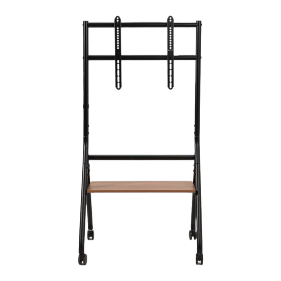
- Page 1 Black Heavy Duty Studio TV Cart with Wooden Shelf SKU: STAND-TV86RD Instruction Manual Assembly Video & Product Info www.vivo-us.com/products/stand-tv86rd...
-
Page 2: Weight Capacity
If you do not understand these directions, or if you have any doubts about the safety of the installation, please contact our product support team at 309-278-5303 or help@vivo-us.com for further assistance. Check carefully to make sure there are no missing or defective parts. Improper installation may cause damage or serious injury. Do not use this product for any purpose that is not explicitly specified in this manual. -
Page 3: Package Contents
Package Contents A (x1) B (x2) C (x3) D (x2) Shelf Vertical Horizontal Left Leg Support Support E (x2) F (x2) G (x1) H (x1) Right Leg VESA Bracket Left Y Right Y Connector Connector I (x4) J (x2) K (x4) L (x2) Caster Cable Clip... -
Page 4: Assembly Steps
ASSEMBLY STEPS STEP 1 Attach one Left and Right Legs (D,E) to each Y Connector Piece (G,H) using the M6x12mm Screws (S-B) and 4mm Allen Wrench (T-A). Note: Make sure all of the holes are facing the same direction when installing the parts together. - Page 5 STEP 2 Thread one Caster (I) onto each Left and Right Legs (D,E). Secure using the 14mm Wrench (T-C). To make the next assembly steps easier, lock the Casters in place by pressing on the Locking Tab. Locking STEP 3 Combine the Leg Assemblies using the Horizontal Support (C) and secure with M8x45mm Screws (S-A) and 5mm Allen Wrench (T-B).
- Page 6 STEP 4 Partially install M6x12mm Screws (S-B) onto the Legs, leaving a 3/16” (4mm) gap exposed. These will be tightened in a future step. Slide the Shelf (A) in between screw head and legs.
- Page 7 STEP 4 - Cont’d Bracket Screws Shelf Not Aligning with Screws? If you are having difficulty aligning the shelf with the screws, loosen the Bracket Screws on the underside of the Shelf using the 4mm Allen Wrench (T-A). With Shelf secured in place, fully tighten the screws using the 4mm Allen Wrench (T-A).
- Page 8 STEP 5 Slide the Vertical Supports (B) into both Y Connectors (G,H) with the lower holes on each facing inward, aligning with each other. Loosely install the M6x12mm Screws (S-B) using the 4mm Allen Wrench (T-A).
- Page 9 STEP 6 Secure the two remaining Horizontal Supports (C) onto the Vertical Supports (B) using M8x45mm Screws (S-A) and 5mm Allen Wrench (T-B). And fully tightened the previously installed screws the 4mm Allen Wrench (T-A). Attach the Cable Clips (J) onto the stand. Fully Tighten Previous Installed Screws...
- Page 10 STEP 7 Use the images below to determine the positioning of the Mounting Brackets (K) based on your desired viewing height. Follow the instructions for your chosen height and secure Mounting Brackets onto the VESA Brackets (F) using the M5x8mm Screws (S-C) and the Phillips end on the 5mm Allen Wrench (T-B).
- Page 11 STEP 8 Install the VESA Brackets (F) onto your display using the appropriate mounting hardware (M-A through M-G). Tighten the screws using the Phillips end on the 5mm Allen Wrench (T-B).
- Page 12 STEP 9 Mounting the Locking Brackets How To Locate Mounting Holes Temporarily Hang TV: With the help of a second person, hand your TV on the upper Horizontal Support (C1). Identify Mounting Holes: Use the image at right to help visualize how the brackets should look after being installed.
- Page 13 Install Locking Brackets: Install Locking Brackets (L) into the mounting holes you observed using the M5x8mm Screws (S-C) and the Phillips end on the 5mm Allen Wrench (T-B). Mount TV: Rotate open the Locking Brackets (L) and mount the TV on the stand.
- Page 14 STEP 10 To level the casters, loosen the lower nuts using the 14mm Wrench (T-C). Once the stand is level, tighten the upper nut using the 14mm Wrench (T-C).
- Page 15 [ THIS PAGE INTENTIONALLY LEFT BLANK ]...
-
Page 16: Last Updated
LAST UPDATED: 06/19/24 REV1.1 v1.0 Need Help? Get In Touch Monday-Friday from 7:00am-7:00pm CST help@vivo-us.com www.vivo-us.com 309-278-5303 Chat live with an agent! FOR MORE GREAT VIVO PRODUCTS, CHECK OUT OUR WEBSITE AT: WWW.VIVO-US.COM VIVO-us @vivo_us...
Need help?
Do you have a question about the STAND-TV86RD and is the answer not in the manual?
Questions and answers