ZyXEL Communications GS2200-24 Series User Manual
Intelligent layer 2 gbe switch intelligent layer 2 gbe switch with poe
Hide thumbs
Also See for GS2200-24 Series:
- User manual (358 pages) ,
- Specifications (4 pages) ,
- Manual (332 pages)
Table of Contents
Advertisement
Quick Links
Advertisement
Table of Contents
Troubleshooting

Subscribe to Our Youtube Channel
Related Manuals for ZyXEL Communications GS2200-24 Series


Summary of Contents for ZyXEL Communications GS2200-24 Series
- Page 1 GS2200-24/24P Series Intelligent Layer 2 GbE Switch Intelligent Layer 2 GbE Switch with PoE Default Login Details IP Address http://192.168.1.1 User Name admin Password 1234 Firmware Version 3.90 Edition 1, 2/2010 www.zyxel.com Copyright © 2010 ZyXEL Communications Corporation...
-
Page 3: About This User's Guide
• Support Disc Refer to the included CD for support documents. Documentation Feedback Send your comments, questions or suggestions to: techwriters@zyxel.com.tw Thank you! The Technical Writing Team, ZyXEL Communications Corp., 6 Innovation Road II, Science-Based Industrial Park, Hsinchu, 30099, Taiwan. - Page 4 • Knowledge Base If you have a specific question about your product, the answer may be here. This is a collection of answers to previously asked questions about ZyXEL products. • Forum This contains discussions on ZyXEL products. Learn from others who use ZyXEL products and share your experiences as well.
-
Page 5: Document Conventions
Syntax Conventions • The GS2200-24 and GS2200-24P may be referred to as the “GS2200-24”, “GS2200-24P”, “Switch”, the “device”, the “system” or the “product” in this User’s Guide. Differentiation is made where needed. - Page 6 Document Conventions Icons Used in Figures Figures in this User’s Guide may use the following generic icons. The Switch icon is not an exact representation of your device. The Switch Computer Notebook computer Server DSLAM Firewall Telephone Router GS2200-24 User’s Guide...
-
Page 7: Safety Warnings
Your product is marked with this symbol, which is known as the WEEE mark. WEEE stands for Waste Electronics and Electrical Equipment. It means that used electrical and electronic products should not be mixed with general waste. Used electrical and electronic equipment should be treated separately. GS2200-24 User’s Guide... - Page 8 Safety Warnings GS2200-24 User’s Guide...
-
Page 9: Table Of Contents
Queuing Method ........................187 ..............................190 Multicast ..........................191 AAA ............................209 IP Source Guard ........................221 Loop Guard ..........................247 Layer 2 Protocol Tunneling ...................... 251 IP Application ........................255 Static Route ..........................257 Differentiated Services ......................261 GS2200-24 User’s Guide... - Page 10 Diagnostic ..........................305 Syslog ............................307 Cluster Management ........................311 MAC Table ..........................319 ARP Table ..........................323 Configure Clone ........................325 Troubleshooting & Product Specifications ............... 327 Troubleshooting ........................329 Product Specifications ......................333 Appendices and Index ......................341 GS2200-24 User’s Guide...
-
Page 11: Table Of Contents
2.3.3 Mounting the Switch on a Rack .................. 31 Chapter 3 Hardware Panels ........................33 3.1 Overview ..........................33 3.2 Front Panels ........................33 3.2.1 Console Port ......................35 3.2.2 Gigabit Ethernet Ports ....................35 3.2.3 Mini-GBIC Slots ......................36 GS2200-24 User’s Guide... - Page 12 6.3.3 Configuring DHCP Relay ................... 65 6.3.4 Troubleshooting ......................65 Chapter 7 System Status and Port Statistics ..................67 7.1 Overview ..........................67 7.1.1 What You Can Do ...................... 67 7.2 Port Status Summary ...................... 68 7.2.1 Status: Port Details ....................70 GS2200-24 User’s Guide...
- Page 13 9.8.1 Create an IP-based VLAN Example ................111 Chapter 10 Static MAC Forward Setup ....................113 10.1 Overview ...........................113 10.1.1 What You Can Do ....................113 10.2 Configuring Static MAC Forwarding ................113 Chapter 11 Static Multicast Forward Setup.................... 117 GS2200-24 User’s Guide...
- Page 14 14.1.1 What You Can Do ....................145 14.2 Bandwidth Control Setup ....................146 Chapter 15 Broadcast Storm Control ..................... 149 15.1 Overview ......................... 149 15.1.1 What You Can Do ....................149 15.2 Broadcast Storm Control Setup ..................150 Chapter 16 Mirroring ..........................153 GS2200-24 User’s Guide...
- Page 15 20.2.1 Viewing and Editing Classifier Configuration ............178 20.3 Classifier Example ......................180 Chapter 21 Policy Rule..........................181 21.1 Policy Rules Overview ....................181 21.1.1 What You Can Do ....................181 21.2 Configuring Policy Rules ....................181 GS2200-24 User’s Guide...
- Page 16 24.6.2 Supported RADIUS Attributes ................219 24.6.3 Attributes Used for Authentication ................219 Chapter 25 IP Source Guard........................221 25.1 Overview .......................... 221 25.1.1 What You Can Do ....................221 25.1.2 What You Need to Know ..................222 GS2200-24 User’s Guide...
- Page 17 Part IV: IP Application................255 Chapter 28 Static Route .......................... 257 28.1 Overview .......................... 257 28.1.1 What You Can Do ....................257 28.2 Configuring Static Routing ....................258 Chapter 29 Differentiated Services ...................... 261 29.1 Overview ......................... 261 GS2200-24 User’s Guide...
- Page 18 31.6.2 Filename Conventions ..................280 31.6.3 FTP Command Line Procedure ................281 31.6.4 GUI-based FTP Clients ..................281 31.6.5 FTP Restrictions ....................282 Chapter 32 Access Control........................283 32.1 Overview ........................283 32.1.1 What You Can Do ....................283 GS2200-24 User’s Guide...
- Page 19 36.1.1 What You Can Do ....................319 36.1.2 What You Need to Know ..................319 36.2 Viewing the MAC Table ....................320 Chapter 37 ARP Table ..........................323 37.1 Overview ......................... 323 37.1.1 What You Can Do ....................323 GS2200-24 User’s Guide...
- Page 20 39.3 Switch Configuration ......................332 Chapter 40 Product Specifications ......................333 Part VII: Appendices and Index ............341 Appendix A Changing a Fuse ....................343 Appendix B Common Services..................... 345 Appendix C Legal Information ....................349 Index............................353 GS2200-24 User’s Guide...
-
Page 21: Introduction And Hardware
Introduction and Hardware Getting to Know Your Switch (23) Hardware Installation and Connection (29) Hardware Panels (33) -
Page 23: Getting To Know Your Switch
H A P T E R Getting to Know Your Switch 1.1 Introduction This chapter introduces the main features and applications of the GS2200-24 and GS2200-24P switches. They are layer-2 standalone Ethernet switch with additional layer-2, layer-3, and layer-4 features suitable for Ethernets. They have twenty-four 10/100/1000 Mbps Ethernet ports. -
Page 24: Bridging Example
Switch. You can provide a super-fast uplink connection by using a Gigabit Ethernet/mini-GBIC port on the Switch. Moreover, the Switch eases supervision and maintenance by allowing network managers to centralize multiple servers at a single location. Figure 2 Bridging Application GS2200-24/24P User’s Guide... -
Page 25: High Performance Switching Example
Ports in the same VLAN group share the same frame broadcast domain thus increase network performance through reduced broadcast traffic. VLAN groups can be modified at any time by adding, moving or changing ports without any re- cabling. GS2200-24/24P User’s Guide... -
Page 26: Ways To Manage The Switch
Do the following things regularly to make the Switch more secure and to manage the Switch more effectively. • Change the password. Use a password that’s not easy to guess and that consists of different types of characters, such as numbers and letters. GS2200-24/24P User’s Guide... - Page 27 If you forget your password, you will have to reset the Switch to its factory default settings. If you backed up an earlier configuration file, you would not have to totally re-configure the Switch. You could simply restore your last configuration. GS2200-24/24P User’s Guide...
- Page 28 Chapter 1 Getting to Know Your Switch GS2200-24/24P User’s Guide...
-
Page 29: Hardware Installation And Connection
The Switch can be mounted on an EIA standard size, 19-inch rack or in a wiring closet with other equipment. Follow the steps below to mount your Switch on a standard EIA rack using a rack-mounting kit. GS2200-24/24P User’s Guide... -
Page 30: Rack-Mounted Installation Requirements
Using a #2 Philips screwdriver, install the M3 flat head screws through the mounting bracket holes into the Switch. Repeat steps to install the second mounting bracket on the other side of the Switch. You may now mount the Switch on a rack. Proceed to the next section. GS2200-24/24P User’s Guide... -
Page 31: Mounting The Switch On A Rack
Figure 6 Mounting the Switch on a Rack Using a #2 Philips screwdriver, install the M5 flat head screws through the mounting bracket holes into the rack. Repeat steps to attach the second mounting bracket on the other side of the rack. GS2200-24/24P User’s Guide... - Page 32 Chapter 2 Hardware Installation and Connection GS2200-24/24P User’s Guide...
-
Page 33: Hardware Panels
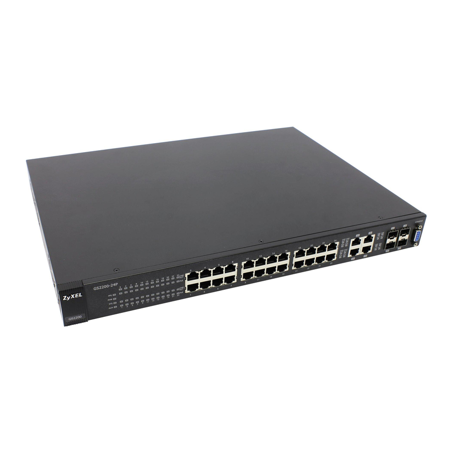
This chapter describes the front panel and rear panel and shows you how to make the hardware connections. 3.2 Front Panels The following figure shows the front panel of the Switch. Figure 7 Front Panel (GS2200-24) LEDs Console Port Dual Personality Interfaces Ethernet Ports GS2200-24/24P User’s Guide... - Page 34 Chapter 3 Hardware Panels The following table describes the port labels on the front panel. Table 1 Front Panel Connections (GS2200-24) LABEL DESCRIPTION 24 10/100/ Connect these ports to a computer, a hub, an Ethernet switch or router. 1000 RJ-45...
-
Page 35: Console Port
An auto-negotiating port can detect and adjust to the optimum Ethernet speed (10/100/1000 Mbps) and duplex mode (full duplex or half duplex) of the connected device. An auto-crossover (auto-MDI/MDI-X) port automatically works with a straight- through or crossover Ethernet cable. GS2200-24/24P User’s Guide... -
Page 36: Mini-Gbic Slots
SFF committee’s INF-8074i specification Rev 1.0 for details. You can change transceivers while the Switch is operating. You can use different transceivers to connect to Ethernet switches with different types of fiber-optic or even copper cable connectors. GS2200-24/24P User’s Guide... -
Page 37: Transceiver Installation
Figure 9 Transceiver Installation Example Figure 10 Connecting the Fiber Optic Cables 3.2.3.2 Transceiver Removal Use the following steps to remove a mini-GBIC transceiver (SFP module). Remove the fiber optic cables from the transceiver. Open the transceiver’s latch (latch styles vary). GS2200-24/24P User’s Guide... -
Page 38: Power Connector
After you connect the power to the Switch, view the LEDs to ensure proper functioning of the Switch and as an aid in troubleshooting. Table 3 LED Descriptions COLOR STATUS DESCRIPTION Green The system is turned on. The system is off or has failed. GS2200-24/24P User’s Guide... - Page 39 The Gigabit port is negotiating in half-duplex mode. (GS2200-24P: for 25~28 copper ports only) Mini-GBIC Slots Green The link to this port is up. The link to this port is not connected. Green Blinking This port is receiving or transmitting data. GS2200-24/24P User’s Guide...
- Page 40 Chapter 3 Hardware Panels GS2200-24/24P User’s Guide...
-
Page 41: Basic Configuration
Basic Configuration The Web Configurator (43) Initial Setup Example (53) System Status and Port Statistics (67) Basic Setting (73) -
Page 43: The Web Configurator
• Java permissions (enabled by default). 4.2 System Login Start your web browser. Type “http://” and the IP address of the Switch (for example, the default management IP address is 192.168.1.1) in the Location or Address field. Press [ENTER]. GS2200-24/24P User’s Guide... -
Page 44: The Status Screen
4.3 The Status Screen The Status screen is the first screen that displays when you access the web configurator. The following figure shows the navigating components of a web configurator screen. Figure 15 Web Configurator Home Screen for GS2200-24 (Status) GS2200-24/24P User’s Guide... - Page 45 C - Click this link to go to the status page of the Switch. D - Click this link to logout of the web configurator. E - Click this link to display web help pages. The help pages provide descriptions for all of the configuration screens. GS2200-24/24P User’s Guide...
- Page 46 Chapter 4 The Web Configurator In the navigation panel, click a main link to reveal a list of submenu links. Table 4 Navigation Panel Sub-links Overview (GS2200-24) ADVANCED BASIC SETTING IP APPLICATION MANAGEMENT APPLICATION GS2200-24 GS2200-24P The following table describes the links in the navigation panel.
- Page 47 This link takes you to a screen where you can configure protection against network loops that occur on the edge of your network. Layer 2 This link takes you to a screen where you can configure L2PT (Layer 2 Protocol Protocol Tunneling) settings on the Switch. Tunneling GS2200-24/24P User’s Guide...
- Page 48 This link takes you to a screen where you can view the MAC addresses – IP address resolution table. Configure This link takes you to a screen where you can copy attributes of one port Clone to other ports. GS2200-24/24P User’s Guide...
-
Page 49: Change Your Password
Click the Save link in the upper right hand corner of the web configurator to save your configuration to nonvolatile memory. Nonvolatile memory refers to the Switch’s storage that remains even if the Switch’s power is turned off. Note: Use the Save link when you are done with a configuration session. GS2200-24/24P User’s Guide... -
Page 50: Switch Lockout
9600 bps with 8 data bits, no parity, one stop bit and flow control set to none. The password will also be reset to “1234” and the IP address to 192.168.1.1. To upload the configuration file, do the following: Connect to the console port using a computer with terminal emulation software. GS2200-24/24P User’s Guide... -
Page 51: Logging Out Of The Web Configurator
Figure 18 Web Configurator: Logout Screen 4.8 Help The web configurator’s online help has descriptions of individual screens and some supplementary information. Click the Help link from a web configurator screen to view an online help description of that screen. GS2200-24/24P User’s Guide... - Page 52 Chapter 4 The Web Configurator GS2200-24/24P User’s Guide...
-
Page 53: Initial Setup Example
You can do this with port-based VLAN or tagged static VLAN with fixed port members. In this example, you want to configure port 1 as a member of VLAN 2. Figure 19 Initial Setup Network Example: VLAN GS2200-24/24P User’s Guide... - Page 54 TX Tagging check box to set the Switch to remove VLAN tags before sending. Click Add to save the settings to the run-time memory. Settings in the run-time memory are lost when the Switch’s power is turned off. GS2200-24/24P User’s Guide...
-
Page 55: Setting Port Vid
Setting link. Enter 2 in the PVID field for port 1 and click Apply to save your changes back to the run-time memory. Settings in the run-time memory are lost when the Switch’s power is turned off. GS2200-24/24P User’s Guide... -
Page 56: Configuring Switch Management Ip Address
This is the same as the VLAN ID you configure in the Static VLAN screen. Click Add to save your changes back to the run-time memory. Settings in the run-time memory are lost when the Switch’s power is turned off. GS2200-24/24P User’s Guide... -
Page 57: Tutorials
Note: For related information about DHCP snooping, see Section 25.1 on page 221. The settings in this tutorial are as the following. Table 6 Tutorial: Settings in this Tutorial PORT DHCP SNOOPING HOST VLAN PVID CONNECTED PORT TRUSTED DHCP Server (A) 1 and 100 GS2200-24/24P User’s Guide... - Page 58 100. Add ports 5, 6 and 7 in the VLAN by selecting Fixed in the Control field as shown. Deselect Tx Tagging because you don’t want outgoing traffic to contain this VLAN tag. Click Add. Figure 23 Tutorial: Create a VLAN and Add Ports to It GS2200-24/24P User’s Guide...
- Page 59 Figure 24 Tutorial: Tag Untagged Frames Go to Advanced Application > IP Source Guard > DHCP snooping > Configure, activate and specify VLAN 100 as the DHCP VLAN as shown. Click Apply. Figure 25 Tutorial: Specify DHCP VLAN GS2200-24/24P User’s Guide...
- Page 60 If you want to add more information in the DHCP request packets such as source VLAN ID or system name, you can also select the Option82 and Information fields in the entry. See Section 25.10.1.3 on page 243. Figure 27 Tutorial: Enable DHCP Snooping on this VLAN GS2200-24/24P User’s Guide...
-
Page 61: How To Use Dhcp Relay On The Switch
DHCP requests. 6.3.1 DHCP Relay Tutorial Introduction In this example, you have configured your DHCP server (192.168.2.3) and want to have it assign a specific IP address (say 172.16.1.18) to DHCP client A based on GS2200-24/24P User’s Guide... -
Page 62: Creating A Vlan
Access the web configurator through the Switch’s management port. Go to Basic Setting > Switch Setup and set the VLAN type to 802.1Q. Click Apply to save the settings to the run-time memory. Figure 30 Tutorial: Set VLAN Type to 802.1Q GS2200-24/24P User’s Guide... - Page 63 Clear the TX Tagging check box to set the Switch to remove VLAN tags before sending. Click Add to save the settings to the run-time memory. Settings in the run-time memory are lost when the Switch’s power is turned off. Figure 31 Tutorial: Create a Static VLAN GS2200-24/24P User’s Guide...
- Page 64 VLAN group that the tag defines. 10 Click Apply to save your changes back to the run-time memory. Figure 33 Tutorial: Add Tag for Frames Received on Port 2 GS2200-24/24P User’s Guide...
-
Page 65: Configuring Dhcp Relay
Click the Save link in the upper right corner of the web configurator to save your configuration permanently. The DHCP server can then assign a specific IP address based on the DHCP request. 6.3.4 Troubleshooting Check the client A’s IP address. If it did not receive the IP address 172.16.1.18, make sure: GS2200-24/24P User’s Guide... - Page 66 Client A is connected to the Switch’s port 2 in VLAN 102. You configured the correct VLAN ID, port number and system name for DHCP relay on both the DHCP server and the Switch. You clicked the Save link on the Switch to have your settings take effect. GS2200-24/24P User’s Guide...
-
Page 67: System Status And Port Statistics
7.1.1 What You Can Do • Use the Port Status Summary screen (Section 7.2 on page 68) to view the port statistics. • Use the Port Details screen (Section 7.2.1 on page 70) to display individual port statistics. GS2200-24/24P User’s Guide... -
Page 68: Port Status Summary
Chapter 7 System Status and Port Statistics 7.2 Port Status Summary To view the port statistics, click Status in all web configurator screens to display the Status screen as shown next. Figure 35 Status (GS2200-24) Figure 36 Status (GS2200-24P) GS2200-24/24P User’s Guide... - Page 69 This field shows the total amount of time in hours, minutes and seconds the port has been up. Clear Counter Enter a port number and then click Clear Counter to erase the recorded statistical information for that port, or select Any to clear statistics for all ports. GS2200-24/24P User’s Guide...
-
Page 70: Status: Port Details
This field displays the speed (either 10M for 10Mbps, 100M for 100Mbps or 1000M for 1000Mbps) and the duplex (F for full duplex or H for half duplex). It also shows the cable type (Copper or Fiber). GS2200-24/24P User’s Guide... - Page 71 Error Packet The following fields display detailed information about packets received that were in error. RX CRC This field shows the number of packets received with CRC (Cyclic Redundant Check) error(s). GS2200-24/24P User’s Guide...
- Page 72 This field shows the number of packets (including bad packets) received that were between 1519 octets and the maximum frame size. The maximum frame size varies depending on your switch model. See Chapter 40 on page 333. GS2200-24/24P User’s Guide...
-
Page 73: Basic Setting
(Section 8.7.1 on page 87) to view the current amount of power that PDs are receiving from the Switch and set the priority levels for the Switch in distributing power to PDs. (This screen is available to GS2200-24P only.) GS2200-24/24P User’s Guide... -
Page 74: System Information
In the navigation panel, click Basic Setting > System Info to display the screen as shown. You can check the firmware version number. Figure 38 Basic Setting > System Info (GS2200-24) Figure 39 Basic Setting > System Info (GS2200-24P) GS2200-24/24P User’s Guide... - Page 75 Current This is the current voltage reading. This field displays the maximum voltage measured at this point. This field displays the minimum voltage measured at this point. GS2200-24/24P User’s Guide...
-
Page 76: General Setup
Enter the geographic location of your Switch. You can use up to 32 printable ASCII characters; spaces are allowed. Contact Enter the name of the person in charge of this Switch. You can use up to Person's Name 32 printable ASCII characters; spaces are allowed. GS2200-24/24P User’s Guide... - Page 77 European Union you would select Last, Sunday, March and the last field depends on your time zone. In Germany for instance, you would select 2:00 because Germany's time zone is one hour ahead of GMT or UTC (GMT+1). GS2200-24/24P User’s Guide...
-
Page 78: Introduction To Vlans
With VLAN, all broadcasts are confined to a specific broadcast domain. Note: VLAN is unidirectional; it only governs outgoing traffic. Chapter 9 on page 93 for information on port-based and 802.1Q tagged VLANs. GS2200-24/24P User’s Guide... -
Page 79: Switch Setup Screen
Leave Time sets the duration of the Leave Period timer for GVRP in milliseconds. Each port has a single Leave Period timer. Leave Time must be two times larger than Join Timer; the default is 600 milliseconds. GS2200-24/24P User’s Guide... -
Page 80: Ip Setup
Use the IP Setup screen to configure the Switch IP address, default gateway device, the default domain name server and the management VLAN ID. The default gateway specifies the IP address of the default gateway (next hop) for outgoing traffic. GS2200-24/24P User’s Guide... -
Page 81: Management Ip Addresses
You can configure up to 64 IP addresses which are used to access and manage the Switch from the ports belonging to the pre-defined VLAN(s). Note: You must configure a VLAN first. Figure 42 Basic Setting > IP Setup GS2200-24/24P User’s Guide... - Page 82 This field displays the index number of the rule. Click an index number to edit the rule. IP Address This field displays the IP address. IP Subnet Mask This field displays the subnet mask. This field displays the ID number of the VLAN group. GS2200-24/24P User’s Guide...
-
Page 83: Port Setup
Click Cancel to clear the selected check boxes in the Delete column. 8.7 Port Setup Use this screen to configure Switch port settings. Click Basic Setting > Port Setup in the navigation panel to display the configuration screen. Figure 43 Basic Setting > Port Setup GS2200-24/24P User’s Guide... - Page 84 Back Pressure flow control is typically used in half duplex mode to send a "collision" signal to the sending port (mimicking a state of packet collision) causing the sending port to temporarily stop sending signals and resend later. Select Flow Control to enable it. GS2200-24/24P User’s Guide...
- Page 85 You can also set priorities so that the Switch is able to reserve and allocate power to certain PDs. Note: The GS2200-24P is compatible with ZyXEL’s PPS250 power module. The PPS250 provides additional external PoE power budget on top of the internal power budget of the GS2200-24P.
- Page 86 Note: The Switch must have at least 16 W of remaining power in order to supply power to a PoE device, even if the PoE device needs less than 16W. Port This is the port index number. GS2200-24/24P User’s Guide...
-
Page 87: Poe Setup
This field displays the maximum amount of current drawn by the PD from (mA) the Switch on this port. 8.7.1 PoE Setup Use this screen to set the priority levels for the Switch in distributing power to PDs. GS2200-24/24P User’s Guide... - Page 88 Port This is the port index number. Select this to provide power to a PD connected to the port. If left unchecked, the PD connected to the port cannot receive power from the Switch. GS2200-24/24P User’s Guide...
- Page 89 Switch loses these changes if it is turned off or loses power, so use the Save link on the top navigation panel to save your changes to the non- volatile memory when you are done configuring. Cancel Click Cancel to begin configuring this screen afresh. GS2200-24/24P User’s Guide...
- Page 90 Chapter 8 Basic Setting GS2200-24/24P User’s Guide...
-
Page 91: Advanced
Advanced VLAN (93) Static MAC Forward Setup (113) Filtering (121) Spanning Tree Protocol (123) Bandwidth Control (145) Broadcast Storm Control (149) Mirroring (153) Link Aggregation (157) Port Authentication (167) Port Security (171) Classifier (175) Policy Rule (181) Queuing Method (187) (190) AAA (209) IP Source Guard (221) -
Page 93: Vlan
A tagged frame is four bytes longer than an untagged frame and contains two bytes of TPID (Tag Protocol Identifier, residing within the type/length GS2200-24/24P User’s Guide... -
Page 94: Automatic Vlan Registration
GARP (Generic Attribute Registration Protocol) allows network switches to register and de-register attribute values with other GARP participants within a bridged LAN. GARP is a protocol that provides a generic mechanism for protocols that serve a more specific application, for example, GVRP. GS2200-24/24P User’s Guide... -
Page 95: Port Vlan Trunking
Enable VLAN Trunking on a port to allow frames belonging to unknown VLAN groups to pass through that port. This is useful if you want to set up VLAN groups on end devices without having to configure the same VLAN groups on intermediary devices. GS2200-24/24P User’s Guide... -
Page 96: Select The Vlan Type
• sent to a group whether it has a VLAN tag or not. • blocked from a VLAN group regardless of its VLAN tag. You can also tag all outgoing frames (that were previously untagged) from a port with the specified VID. GS2200-24/24P User’s Guide... -
Page 97: Vlan Status
This field shows how this VLAN was added to the Switch. dynamic: using GVRP static: added as a permanent entry Change Pages Click Previous or Next to show the previous/next screen if all status information cannot be seen in one screen. GS2200-24/24P User’s Guide... -
Page 98: Vlan Details
This field shows how long it has been since a normal VLAN was registered or a static VLAN was set up. Status This field shows how this VLAN was added to the Switch. dynamic: using GVRP static: added as a permanent entry GS2200-24/24P User’s Guide... -
Page 99: Configure A Static Vlan
This name consists of up to 64 printable characters. VLAN Group Enter the VLAN ID for this static entry; the valid range is between 1 and 4094. Port The port number identifies the port you are configuring. GS2200-24/24P User’s Guide... - Page 100 This field indicates whether the VLAN settings are enabled (Yes) or disabled (No). Name This field displays the descriptive name for this VLAN group. Delete Click Delete to remove the selected entry from the summary table. Cancel Click Cancel to clear the Delete check boxes. GS2200-24/24P User’s Guide...
-
Page 101: Configure Vlan Port Settings
If this check box is selected, the Switch discards incoming frames on a port for VLANs that do not include this port in its member set. Clear this check box to disable ingress filtering. Port This field displays the port number. GS2200-24/24P User’s Guide... -
Page 102: Subnet Based Vlans
IP subnet it came from. The untagged packets from the same IP subnet are then placed in the same subnet based VLAN. One advantage of using subnet based VLANs is that priority can be assigned to traffic from the same IP subnet. GS2200-24/24P User’s Guide... -
Page 103: Configuring Subnet Based Vlan
Internet Untagged Frames 10.1.1.0/24 172.16.1.0/24 192.168.1.0/24 VID = 300 VID = 100 VID = 200 9.5.1 Configuring Subnet Based VLAN Click Subnet Based VLAN in the VLAN Port Setting screen to display the configuration screen as shown. GS2200-24/24P User’s Guide... - Page 104 1’s together. Take “255.255.255.0” for example. 255 converts to eight 1s in binary. There are three 255s, so add three eights together and you get the bit number (24). GS2200-24/24P User’s Guide...
-
Page 105: Protocol Based Vlans
ARP traffic received on port 1, 2 and 3. You also have a protocol based VLAN B with priority 2 for Apple Talk traffic received on port 6 and 7. All upstream ARP traffic from port 1, 2 and 3 will be grouped together, and all upstream Apple Talk GS2200-24/24P User’s Guide... -
Page 106: Configuring Protocol Based Vlan
Click Protocol Based VLAN in the VLAN Port Setting screen to display the configuration screen as shown. Note: Protocol-based VLAN applies to un-tagged packets and is applicable only when you use IEEE 802.1Q tagged VLAN. Figure 56 Advanced Application > VLAN > VLAN Port Setting > Protocol Based VLAN GS2200-24/24P User’s Guide... - Page 107 This field shows the priority which is assigned to frames belonging to this protocol based VLAN. Delete Click this to delete the protocol based VLANs which you marked for deletion. Cancel Click Cancel to begin configuring this screen afresh. GS2200-24/24P User’s Guide...
-
Page 108: Port-Based Vlan Setup
Note: In screens (such as IP Setup and Filtering) that require a VID, you must enter 1 as the VID. The port-based VLAN setup screen is shown next. The CPU management port forms a VLAN with all Ethernet ports. GS2200-24/24P User’s Guide... -
Page 109: Configure A Port-Based Vlan
Select Port Based as the VLAN Type in the Basic Setting > Switch Setup screen and then click Advanced Application > VLAN from the navigation panel to display the next screen. Figure 57 Port Based VLAN Setup (All Connected) GS2200-24/24P User’s Guide... - Page 110 Chapter 9 VLAN Figure 58 Port Based VLAN Setup (Port Isolation) GS2200-24/24P User’s Guide...
-
Page 111: Technical Reference
This section provides technical background information on the topics discussed in this chapter. 9.8.1 Create an IP-based VLAN Example This example shows you how to create an IP VLAN which includes ports 1, 4 and 8. Follow these steps: GS2200-24/24P User’s Guide... - Page 112 To add more ports to this protocol based VLAN. Click the index number of the protocol based VLAN entry. Click 1 Change the value in the Port field to the next port you want to add. Click Add. GS2200-24/24P User’s Guide...
-
Page 113: Static Mac Forward Setup
Static MAC address forwarding together with port security allow only computers in the MAC address table on a port to access the Switch. See Chapter 19 on page for more information on port security. GS2200-24/24P User’s Guide... - Page 114 MAC address-forwarding rule. MAC Address This field displays the MAC address that will be forwarded and the VLAN identification number to which the MAC address belongs. This field displays the ID number of the VLAN group. GS2200-24/24P User’s Guide...
- Page 115 This field displays the port where the MAC address shown in the next field will be forwarded. Delete Click Delete to remove the selected entry from the summary table. Cancel Click Cancel to clear the Delete check boxes. GS2200-24/24P User’s Guide...
- Page 116 Chapter 10 Static MAC Forward Setup GS2200-24/24P User’s Guide...
-
Page 117: Static Multicast Forward Setup
23.3 on page 195). Figure 61 shows such unknown multicast frames flooded to all ports. With static multicast forwarding, you can forward these multicasts to port(s) within a VLAN group. Figure 62 shows frames being forwarded to devices GS2200-24/24P User’s Guide... -
Page 118: Configuring Static Multicast Forwarding
Figure 62 Static Multicast Forwarding to A Single Port Figure 63 Static Multicast Forwarding to Multiple Ports 11.2 Configuring Static Multicast Forwarding Use this screen to configure rules to forward specific multicast frames, such as streaming or control frames, to specific port(s). GS2200-24/24P User’s Guide... - Page 119 Cancel Click Cancel to reset the fields to their last saved values. Clear Click Clear to begin configuring this screen afresh. Index Click an index number to modify a static multicast MAC address rule for port(s). GS2200-24/24P User’s Guide...
- Page 120 This field displays the port(s) within a identified VLAN group to which frames containing the specified multicast MAC address will be forwarded. Delete Click Delete to remove the selected entry from the summary table. Cancel Click Cancel to clear the Delete check boxes. GS2200-24/24P User’s Guide...
-
Page 121: Filtering
12.2 Configure a Filtering Rule Use this screen to create rules for traffic going through the Switch. Click Advanced Application > Filtering in the navigation panel to display the screen as shown next. Figure 65 Advanced Application > Filtering GS2200-24/24P User’s Guide... - Page 122 This field displays the VLAN group identification number. Delete Check the rule(s) that you want to remove in the Delete column and then click the Delete button. Cancel Click Cancel to clear the selected checkbox(es) in the Delete column. GS2200-24/24P User’s Guide...
-
Page 123: Spanning Tree Protocol
134) to view the MRSTP status. • Use the Multiple Spanning Tree Protocol screen (Section 13.8 on page 136) to configure MSTP. • Use the Multiple Spanning Tree Protocol Status screen (Section 13.9 on page 139) to view the MSTP status. GS2200-24/24P User’s Guide... -
Page 124: What You Need To Know
It is the port on this switch with the lowest path cost to the root (the root path cost). If there is no root port, then this switch has been accepted as the root bridge of the spanning tree network. GS2200-24/24P User’s Guide... - Page 125 Multiple RSTP MRSTP (Multiple RSTP) is ZyXEL’s proprietary feature that is compatible with RSTP and STP. With MRSTP, you can have more than one spanning tree on your Switch and assign port(s) to each tree. Each spanning tree operates independently with its own bridge information.
- Page 126 • A VLAN can be mapped to a specific Multiple Spanning Tree Instance (MSTI). MSTI allows multiple VLANs to use the same spanning tree. • Load-balancing is possible as traffic from different VLANs can use distinct paths in a region. GS2200-24/24P User’s Guide...
-
Page 127: Spanning Tree Protocol Status Screen
13.3 Spanning Tree Configuration Use the Spanning Tree Configuration screen to activate one of the STP modes on the Switch. Click Configuration in the Advanced Application > Spanning Tree Protocol. Figure 68 Advanced Application > Spanning Tree Protocol > Configuration GS2200-24/24P User’s Guide... -
Page 128: Configure Rapid Spanning Tree Protocol
Use this screen to configure RSTP settings, see Section 13.1 on page 123 for more information on RSTP. Click RSTP in the Advanced Application > Spanning Tree Protocol screen. Figure 69 Advanced Application > Spanning Tree Protocol > RSTP GS2200-24/24P User’s Guide... - Page 129 Use this row only if you want to make some settings the same for all ports. Use this row first to set the common settings and then make adjustments on a port-by-port basis. Note: Changes in this row are copied to all the ports as soon as you make them. GS2200-24/24P User’s Guide...
-
Page 130: Rapid Spanning Tree Protocol Status
See Section 13.1 on page 123 more information on RSTP. Note: This screen is only available after you activate RSTP on the Switch. Figure 70 Advanced Application > Spanning Tree Protocol > Status: RSTP GS2200-24/24P User’s Guide... - Page 131 Switch must communicate with the root of the Spanning Tree. Topology This is the number of times the spanning tree has been reconfigured. Changed Times Time Since Last This is the time since the spanning tree was last reconfigured. Change GS2200-24/24P User’s Guide...
-
Page 132: Configure Multiple Rapid Spanning Tree Protocol
Select this check box to activate an STP tree. Clear this checkbox to disable an STP tree. Note: You must also activate Multiple Rapid Spanning Tree in the Advanced Application > Spanning Tree Protocol > Configuration screen to enable MRSTP on the Switch. GS2200-24/24P User’s Guide... - Page 133 Path cost is the cost of transmitting a frame on to a LAN through that port. It is recommended to assign this value according to the speed of the bridge. The slower the media, the higher the cost-see Table 27 on page 124 for more information. GS2200-24/24P User’s Guide...
-
Page 134: Multiple Rapid Spanning Tree Protocol Status
Bridge is this switch. This Switch may also be the root bridge. Bridge ID This is the unique identifier for this bridge, consisting of bridge priority plus MAC address. This ID is the same for Root and Our Bridge if the Switch is the root switch. GS2200-24/24P User’s Guide... - Page 135 Switch must communicate with the root of the Spanning Tree. Topology This is the number of times the spanning tree has been reconfigured. Changed Times Time Since Last This is the time since the spanning tree was last reconfigured. Change GS2200-24/24P User’s Guide...
-
Page 136: Configure Multiple Spanning Tree Protocol
13.8 Configure Multiple Spanning Tree Protocol To configure MSTP, click MSTP in the Advanced Application > Spanning Tree Protocol screen. See Section on page 126 for more information on MSTP. Figure 73 Advanced Application > Spanning Tree Protocol > MSTP GS2200-24/24P User’s Guide... - Page 137 Click Cancel to begin configuring this screen afresh. Instance Use this section to configure MSTI (Multiple Spanning Tree Instance) settings. Instance Enter the number you want to use to identify this MST instance on the Switch. The Switch supports instance numbers 0-15. GS2200-24/24P User’s Guide...
- Page 138 This field displays the ID of an MST instance. VLAN This field displays the VID (or VID ranges) to which the MST instance is mapped. Active Port This field display the ports configured to participate in the MST instance. GS2200-24/24P User’s Guide...
-
Page 139: Multiple Spanning Tree Protocol Status
See Section on page 126 for more information on MSTP. Note: This screen is only available after you activate MSTP on the Switch. Figure 74 Advanced Application > Spanning Tree Protocol > Status: MSTP GS2200-24/24P User’s Guide... - Page 140 This Switch may also be the root bridge. Bridge ID This is the unique identifier for this bridge, consisting of bridge priority plus MAC address. This ID is the same for Root and Our Bridge if the Switch is the root switch. GS2200-24/24P User’s Guide...
-
Page 141: Technical Reference
If the switches are using STP or RSTP, the link for VLAN 2 will be blocked as STP and RSTP allow only one link in the network and block the redundant link. Figure 75 STP/RSTP Network Example VLAN 1 VLAN 2 GS2200-24/24P User’s Guide... -
Page 142: Mst Region
An MST Instance (MSTI) is a spanning tree instance. VLANs can be configured to run on a specific MSTI. Each created MSTI is identified by a unique number (known as an MST ID) known internally to a region. Thus an MSTI does not span across MST regions. GS2200-24/24P User’s Guide... -
Page 143: Common And Internal Spanning Tree (Cist)
MSTP-enabled network, there is only one CIST that runs between MST regions and single spanning tree devices. A network may contain multiple MST regions and other network segments running RSTP. Figure 78 MSTP and Legacy RSTP Network Example GS2200-24/24P User’s Guide... - Page 144 Chapter 13 Spanning Tree Protocol GS2200-24/24P User’s Guide...
-
Page 145: Bandwidth Control
Bandwidth control means defining a maximum allowable bandwidth for incoming and/or out-going traffic flows on a port. 14.1.1 What You Can Do Use the Bandwidth Control screen (Section 14.2 on page 146) to limit the bandwidth for traffic going through the Switch. GS2200-24/24P User’s Guide... -
Page 146: Bandwidth Control Setup
Select this check box to activate ingress rate limits on this port. Ingress Rate Active Select this check box to activate egress rate limits on this port. Egress Rate Specify the maximum bandwidth allowed in kilobits per second (Kbps) for the out-going traffic flow on a port. GS2200-24/24P User’s Guide... - Page 147 Switch loses these changes if it is turned off or loses power, so use the Save link on the top navigation panel to save your changes to the non- volatile memory when you are done configuring. Cancel Click Cancel to reset the fields. GS2200-24/24P User’s Guide...
- Page 148 Chapter 14 Bandwidth Control GS2200-24/24P User’s Guide...
-
Page 149: Broadcast Storm Control
15.1.1 What You Can Do Use the Broadcast Storm Control screen (Section 15.2 on page 150) to limit the number of broadcast, multicast and destination lookup failure (DLF) packets the Switch receives per second on the ports. GS2200-24/24P User’s Guide... -
Page 150: Broadcast Storm Control Setup
Multicast (pkt/ Select this option and specify how many multicast packets the port receives per second. DLF (pkt/s) Select this option and specify how many destination lookup failure (DLF) packets the port receives per second. GS2200-24/24P User’s Guide... - Page 151 Switch loses these changes if it is turned off or loses power, so use the Save link on the top navigation panel to save your changes to the non- volatile memory when you are done configuring. Cancel Click Cancel to reset the fields. GS2200-24/24P User’s Guide...
- Page 152 Chapter 15 Broadcast Storm Control GS2200-24/24P User’s Guide...
-
Page 153: Mirroring
16.1.1 What You Can Do Use the Mirroring screen (Section 16.2 on page 154) to select a monitor port and specify the traffic flow to be copied to the monitor port. GS2200-24/24P User’s Guide... -
Page 154: Port Mirroring Setup
Use this row only if you want to make some settings the same for all ports. Use this row first to set the common settings and then make adjustments on a port-by-port basis. Note: Changes in this row are copied to all the ports as soon as you make them. GS2200-24/24P User’s Guide... - Page 155 Switch loses these changes if it is turned off or loses power, so use the Save link on the top navigation panel to save your changes to the non-volatile memory when you are done configuring. Cancel Click Cancel to reset the fields. GS2200-24/24P User’s Guide...
- Page 156 Chapter 16 Mirroring GS2200-24/24P User’s Guide...
-
Page 157: Link Aggregation
Note: In a properly planned network, it is recommended to implement static link aggregation only. This ensures increased network stability and control over the trunk groups on your Switch. Section 17.5.1 on page 164 for a static port trunking example. GS2200-24/24P User’s Guide... - Page 158 Table 40 Link Aggregation ID: Peer Switch SYSTEM PORT MAC ADDRESS PORT NUMBER PRIORITY PRIORITY 0000 00-00-00-00-00-00 0000 0000 Port Priority and Port Number are 0 as it is the aggregator ID for the trunk group, not the individual port. GS2200-24/24P User’s Guide...
-
Page 159: Link Aggregation Status
Refer to Section on page 158 for more information on this field. The ID displays only when there is a port belonging to this trunk group and LACP is also enabled for this group. GS2200-24/24P User’s Guide... - Page 160 This field displays how these ports were added to the trunk group. It displays: • Static - if the ports are configured as static members of a trunk group. • LACP - if the ports are configured to join a trunk group via LACP. GS2200-24/24P User’s Guide...
-
Page 161: Link Aggregation Setting
This is the only screen you need to configure to enable static link Aggregation aggregation. Setting Group ID The field identifies the link aggregation group, that is, one logical link containing multiple ports. Active Select this option to activate a trunk group. GS2200-24/24P User’s Guide... - Page 162 Switch loses these changes if it is turned off or loses power, so use the Save link on the top navigation panel to save your changes to the non- volatile memory when you are done configuring. Cancel Click Cancel to begin configuring this screen afresh. GS2200-24/24P User’s Guide...
-
Page 163: Link Aggregation Control Protocol
Table 43 Advanced Application > Link Aggregation > Link Aggregation Setting > LACP LABEL DESCRIPTION Link Note: Do not configure this screen unless you want to enable Aggregation dynamic link aggregation. Control Protocol Active Select this checkbox to enable Link Aggregation Control Protocol (LACP). GS2200-24/24P User’s Guide... -
Page 164: Technical Reference
Click Cancel to begin configuring this screen afresh. 17.5 Technical Reference This section provides technical background information on the topics discussed in this chapter. 17.5.1 Static Trunking Example This example shows you how to create a static port trunk group for ports 2-5. GS2200-24/24P User’s Guide... - Page 165 Click Apply when you are done. Figure 86 Trunking Example - Configuration Screen Your trunk group 1 (T1) configuration is now complete. GS2200-24/24P User’s Guide...
- Page 166 Chapter 17 Link Aggregation GS2200-24/24P User’s Guide...
-
Page 167: Port Authentication
When the client provides the login credentials, the Switch sends an authentication At the time of writing, IEEE 802.1x is not supported by all operating systems. See your operating system documentation. If your operating system does not support 802.1x, then you may need to install 802.1x client software. GS2200-24/24P User’s Guide... -
Page 168: Port Authentication Configuration
Switch and the port(s)) then configure the RADIUS server settings in the Auth and Acct > Radius Server Setup screen. Click Advanced Application > Port Authentication in the navigation panel to display the screen as shown. Figure 88 Advanced Application > Port Authentication GS2200-24/24P User’s Guide... -
Page 169: Activate Ieee 802.1X Security
Use this row only if you want to make some settings the same for all ports. Use this row first to set the common settings and then make adjustments on a port-by-port basis. Note: Changes in this row are copied to all the ports as soon as you make them. GS2200-24/24P User’s Guide... - Page 170 Switch loses these changes if it is turned off or loses power, so use the Save link on the top navigation panel to save your changes to the non- volatile memory when you are done configuring. Cancel Click Cancel to begin configuring this screen afresh. GS2200-24/24P User’s Guide...
-
Page 171: Port Security
19.1.1 What You Can Do Use the Port Security screen (Section 19.2 on page 172) to enable port security and disable MAC address learning. You can also enable the port security feature on a port. GS2200-24/24P User’s Guide... -
Page 172: Port Security Setup
Click MAC freeze to have the Switch automatically select the Active check boxes and clear the Address Learning check boxes only for the ports specified in the Port list. Active Select this option to enable port security on the Switch. Port This field displays the port number. GS2200-24/24P User’s Guide... - Page 173 Switch loses these changes if it is turned off or loses power, so use the Save link on the top navigation panel to save your changes to the non- volatile memory when you are done configuring. Cancel Click Cancel to begin configuring this screen afresh. GS2200-24/24P User’s Guide...
- Page 174 Chapter 19 Port Security GS2200-24/24P User’s Guide...
-
Page 175: Classifier
Setting up QoS involves two separate steps: Configure classifiers to sort traffic into different flows. Configure policy rules to define actions to be performed on a classified traffic flow (refer to Chapter 21 on page 181 to configure policy rules). GS2200-24/24P User’s Guide... -
Page 176: Configuring The Classifier
Table 46 Advanced Application > Classifier LABEL DESCRIPTION Active Select this option to enable this rule. Name Enter a descriptive name for this rule for identifying purposes. Layer 2 Specify the fields below to configure a layer 2 classifier. GS2200-24/24P User’s Guide... - Page 177 Select Any to apply the rule to all TCP/UDP protocol port numbers or select the second option and enter a TCP/UDP protocol port number. Refer to Table 50 on page 179 for more information. GS2200-24/24P User’s Guide...
-
Page 178: Viewing And Editing Classifier Configuration
Click Cancel to clear the Delete check boxes. The following table shows some other common Ethernet types and the corresponding protocol number. Table 48 Common Ethernet Types and Protocol Numbers ETHERNET TYPE PROTOCOL NUMBER IP ETHII 0800 X.75 Internet 0801 GS2200-24/24P User’s Guide... - Page 179 Some of the most common TCP and UDP port numbers are: Table 50 Common TCP and UDP Port Numbers PROTOCOL NAME TCP/UDP PORT NUMBER Telnet SMTP HTTP POP3 Appendix B on page 345 for information on commonly used port numbers. GS2200-24/24P User’s Guide...
-
Page 180: Classifier Example
MAC address 00:50:ba:ad:4f:81 on port 2. After you have configured a classifier, you can configure a policy (in the Policy screen) to define action(s) on the classified traffic flow. Figure 93 Classifier: Example GS2200-24/24P User’s Guide... -
Page 181: Policy Rule
181) to enable the policy and display the active classifier(s) you configure in the Classifier screen. 21.2 Configuring Policy Rules You must first configure a classifier in the Classifier screen. Refer to Section 20.2 on page 176 for more information. GS2200-24/24P User’s Guide... - Page 182 [SHIFT] and select the choices at the same time. Parameters Set the fields below for this policy. You only have to set the field(s) that is related to the action(s) you configure in the Action field. General VLAN ID Specify a VLAN ID number. GS2200-24/24P User’s Guide...
- Page 183 Select Send the packet to the egress port to send the packet to the egress port. Select Set the packet's VLAN ID to replace the VLAN ID of the packets with the value you configure in the VLAN ID field. GS2200-24/24P User’s Guide...
-
Page 184: Viewing And Editing Policy Configuration
To view a summary of the classifier configuration, scroll down to the summary table at the bottom of the Policy screen. To change the settings of a rule, click a number in the Index field. Figure 95 Advanced Application > Policy Rule: Summary Table GS2200-24/24P User’s Guide... -
Page 185: Policy Example
21.3 Policy Example The figure below shows an example Policy screen where you configure a policy to limit bandwidth on a traffic flow classified using the Example classifier (refer to Section 20.3 on page 180). Figure 96 Policy Example GS2200-24/24P User’s Guide... - Page 186 Chapter 21 Policy Rule GS2200-24/24P User’s Guide...
-
Page 187: Queuing Method
(portion) (the number you configure in the Weight field) when there is traffic congestion. WFQ is activated only when a port has more traffic than it can handle. Queues with larger weights get more guaranteed GS2200-24/24P User’s Guide... -
Page 188: Configuring Queuing
22.2 Configuring Queuing Use this screen to set priorities for the queues of the Switch. This distributes bandwidth across the different traffic queues. GS2200-24/24P User’s Guide... - Page 189 Use this row only if you want to make some settings the same for all ports. Use this row first to set the common settings and then make adjustments on a port-by-port basis. Note: Changes in this row are copied to all the ports as soon as you make them. GS2200-24/24P User’s Guide...
- Page 190 Switch loses these changes if it is turned off or loses power, so use the Save link on the top navigation panel to save your changes to the non-volatile memory when you are done configuring. Cancel Click Cancel to begin configuring this screen afresh. GS2200-24/24P User’s Guide...
-
Page 191: Multicast
192) to create multicast VLANs and select the receiver port(s) and a source port for each multicast VLAN. 23.1.2 What You Need to Know Read on for concepts on Multicasting that can help you configure the screens in this chapter. GS2200-24/24P User’s Guide... -
Page 192: Mvr Overview
VLANs on the network. While isolated in different subscriber VLANs, connected devices can subscribe to and unsubscribe from the multicast stream in the multicast VLAN. This improves bandwidth utilization with reduced multicast traffic in the subscriber VLANs and simplifies multicast group management. GS2200-24/24P User’s Guide... - Page 193 S, via the Switch. Multiple subscriber devices can connect through a port configured as the receiver on the Switch. When the subscriber selects a television channel, computer A sends an IGMP report to the Switch to join the appropriate multicast group. If the IGMP report GS2200-24/24P User’s Guide...
-
Page 194: Multicast Status
This is the index number of the entry. This field displays the multicast VLAN ID. Port This field displays the port number that belongs to the multicast group. Multicast Group This field displays IP multicast group addresses. GS2200-24/24P User’s Guide... -
Page 195: Multicast Setting
VLANs with the multicast hosts attached. Host Timeout Specify the time (from 1 to 16,711,450) in seconds that elapses before the Switch removes an IGMP group membership entry if it does not receive report messages from the port. GS2200-24/24P User’s Guide... - Page 196 This defines how many seconds the Switch waits for an IGMP report before removing an IGMP snooping membership entry when an IGMP leave message is received on this port from a host. GS2200-24/24P User’s Guide...
- Page 197 Switch loses these changes if it is turned off or loses power, so use the Save link on the top navigation panel to save your changes to the non- volatile memory when you are done configuring. Cancel Click Cancel to begin configuring this screen afresh. GS2200-24/24P User’s Guide...
-
Page 198: Igmp Snooping Vlan
Click Apply to save your changes to the Switch’s run-time memory. The Switch loses these changes if it is turned off or loses power, so use the Save link on the top navigation panel to save your changes to the non- volatile memory when you are done configuring. GS2200-24/24P User’s Guide... -
Page 199: Igmp Filtering Profile
(in the Multicast Setting screen). Clients connected to those ports are then able to join the multicast groups specified in the profile. Each port can be assigned a single profile. A profile can be assigned to multiple ports. GS2200-24/24P User’s Guide... - Page 200 Click Clear to clear the fields to the factory defaults. Profile Name This field displays the descriptive name of the profile. Start Address This field displays the start of the multicast address range. End Address This field displays the end of the multicast address range. GS2200-24/24P User’s Guide...
-
Page 201: The Mvr Screen
VLAN. Click Advanced Applications > Multicast > Multicast Setting > MVR link to display the screen as shown next. Note: You can create up to three multicast VLANs and up to 256 multicast rules on the Switch. GS2200-24/24P User’s Guide... - Page 202 Compatible. Select Dynamic to send IGMP reports to all MVR source ports in the multicast VLAN. Select Compatible to set the Switch not to send IGMP reports. Port This field displays the port number on the Switch. GS2200-24/24P User’s Guide...
-
Page 203: Mvr Group Configuration
All source ports and receiver ports belonging to a multicast group can receive multicast data sent to this multicast group. Configure MVR IP multicast group address(es) in the Group Configuration screen. Click Group Configuration in the MVR screen. GS2200-24/24P User’s Guide... - Page 204 This field displays the multicast VLAN ID. Name This field displays the descriptive name for this setting. Start This field displays the starting IP address of the multicast group. Address End Address This field displays the ending IP address of the multicast group. GS2200-24/24P User’s Guide...
-
Page 205: Mvr Configuration Example
VID 200 to receive multicast traffic (the News and Movie channels) from the remote streaming media server, S. Computers A, B and C in VLAN 1 are able to receive the traffic. Figure 106 MVR Configuration Example GS2200-24/24P User’s Guide... - Page 206 To configure the MVR settings on the Switch, create a multicast group in the MVR screen and set the receiver and source ports. Figure 107 MVR Configuration Example To set the Switch to forward the multicast group traffic to the subscribers, configure multicast group settings in the Group Configuration screen. The GS2200-24/24P User’s Guide...
- Page 207 Chapter 23 Multicast following figure shows an example where two multicast groups (News and Movie) are configured for the multicast VLAN 200. Figure 108 MVR Group Configuration Example Figure 109 MVR Group Configuration Example GS2200-24/24P User’s Guide...
- Page 208 Chapter 23 Multicast GS2200-24/24P User’s Guide...
-
Page 209: Aaa
Switch should use first. 24.1.2 What You Need to Know Authentication is the process of determining who a user is and validating access to the Switch. The Switch can authenticate users who try to log in based on user GS2200-24/24P User’s Guide... -
Page 210: Aaa Screens
24.2 AAA Screens The AAA screens allow you to enable authentication and authorization or both of them on the Switch. First, configure your authentication server settings (RADIUS, TACACS+ or both) and then set up the authentication priority, activate authorization. GS2200-24/24P User’s Guide... -
Page 211: Radius Server Setup
RADIUS attributes utilized by the authentication features on the Switch. Click on the RADIUS Server Setup link in the AAA screen to view the screen as shown. Figure 112 Advanced Application > AAA > RADIUS Server Setup GS2200-24/24P User’s Guide... - Page 212 Switch loses these changes if it is turned off or loses power, so use the Save link on the top navigation panel to save your changes to the non- volatile memory when you are done configuring. Cancel Click Cancel to begin configuring this screen afresh. GS2200-24/24P User’s Guide...
-
Page 213: Tacacs+ Server Setup
Select index-priority and the Switch tries to authenticate with the first configured TACACS+ server, if the TACACS+ server does not respond then the Switch tries to authenticate with the second TACACS+ server. Select round-robin to alternate between the TACACS+ servers that it sends authentication requests to. GS2200-24/24P User’s Guide... - Page 214 Switch loses these changes if it is turned off or loses power, so use the Save link on the top navigation panel to save your changes to the non- volatile memory when you are done configuring. Cancel Click Cancel to begin configuring this screen afresh. GS2200-24/24P User’s Guide...
-
Page 215: Aaa Setup
Use this screen to configure authentication and authorization settings on the Switch. Click on the AAA Setup link in the AAA screen to view the screen as shown. Figure 114 Advanced Application > AAA > AAA Setup GS2200-24/24P User’s Guide... - Page 216 Exec: Allow an administrator which logs in the Switch through Telnet or SSH to have different access privilege level assigned via the external server. • Dot1x: Allow an IEEE 802.1x client to have different bandwidth limit or VLAN ID assigned via the external server. GS2200-24/24P User’s Guide...
-
Page 217: Technical Reference
The VSAs are composed of the following: • Vendor-ID: An identification number assigned to the company by the IANA (Internet Assigned Numbers Authority). ZyXEL’s vendor ID is 890. • Vendor-Type: A vendor specified attribute, identifying the setting you want to modify. -
Page 218: Tunnel Protocol Attribute
Note that the bolded values in the table are fixed values as defined in RFC 3580. Table 64 Supported Tunnel Protocol Attribute FUNCTION ATTRIBUTE VLAN Assignment Tunnel-Type = VLAN(13) Tunnel-Medium-Type = 802(6) Tunnel-Private-Group-ID = VLAN ID Note: You must also create a VLAN with the specified VID on the Switch. GS2200-24/24P User’s Guide... -
Page 219: Supported Radius Attributes
- The format of the User-Name attribute is $enab#$, where # is the privilege level (1-14). User-Password NAS-Identifier NAS-IP-Address 24.6.3.2 Attributes Used to Login Users User-Name User-Password NAS-Identifier NAS-IP-Address 24.6.3.3 Attributes Used by the IEEE 802.1x Authentication User-Name NAS-Identifier NAS-IP-Address NAS-Port NAS-Port-Type GS2200-24/24P User’s Guide... - Page 220 Chapter 24 AAA - This value is set to Ethernet(15) on the Switch. Calling-Station-Id Frame-MTU EAP-Message State Message-Authenticator GS2200-24/24P User’s Guide...
-
Page 221: Ip Source Guard
231) to enable DHCP snooping on each VLAN and to specify whether or not the Switch adds DHCP relay agent option 82 information to DHCP requests that the Switch relays to a DHCP server for each VLAN. GS2200-24/24P User’s Guide... -
Page 222: What You Need To Know
Use this screen to look at the current bindings for DHCP snooping and ARP inspection. Bindings are used by DHCP snooping and ARP inspection to distinguish between authorized and unauthorized packets in the network. The Switch learns the bindings by snooping DHCP packets (dynamic bindings) and from information GS2200-24/24P User’s Guide... -
Page 223: Ip Source Guard Static Binding
Static bindings are uniquely identified by the MAC address and VLAN ID. Each MAC address and VLAN ID can only be in one static binding. If you try to create a static binding with the same MAC address and VLAN ID as an existing static binding, the GS2200-24/24P User’s Guide... - Page 224 This field displays how long the binding is valid. Type This field displays how the Switch learned the binding. static: This binding was learned from information provided manually by an administrator. VLAN This field displays the source VLAN ID in the binding. GS2200-24/24P User’s Guide...
-
Page 225: Dhcp Snooping
Click this to clear the Delete check boxes above. 25.4 DHCP Snooping Use this screen to look at various statistics about the DHCP snooping database. To open this screen, click Advanced Application > IP Source Guard > DHCP Snooping. Figure 117 DHCP Snooping GS2200-24/24P User’s Guide... - Page 226 DHCP snooping database for any reason. Startup failures This field displays the number of times the Switch could not create or read the DHCP snooping database when the Switch started up or a new URL is configured for the DHCP snooping database. GS2200-24/24P User’s Guide...
- Page 227 Switch already had a binding with the same MAC address and VLAN ID. Invalid interfaces This field displays the number of bindings the Switch has ignored because the port number was a trusted interface or does not exist anymore. GS2200-24/24P User’s Guide...
-
Page 228: Dhcp Snooping Configure
TFTP server so that they are still available after a restart. To open this screen, click Advanced Application > IP Source Guard > DHCP Snooping > Configure. Figure 118 DHCP Snooping Configure GS2200-24/24P User’s Guide... - Page 229 If there is a conflict, the Switch keeps the dynamic binding in volatile memory and updates the Binding collisions counter in the DHCP Snooping screen (Section 25.4 on page 225). GS2200-24/24P User’s Guide...
-
Page 230: Dhcp Snooping Port Configure
You can also specify the maximum number for DHCP packets that each port (trusted or untrusted) can receive each second. To open this screen, click Advanced Application > IP Source Guard > DHCP Snooping > Configure > Port. Figure 119 DHCP Snooping Port Configure GS2200-24/24P User’s Guide... -
Page 231: Dhcp Snooping Vlan Configure
Use this screen to enable DHCP snooping on each VLAN and to specify whether or not the Switch adds DHCP relay agent option 82 information (Chapter 30 on page 265) to DHCP requests that the Switch relays to a DHCP server for each VLAN. To GS2200-24/24P User’s Guide... - Page 232 The Switch loses these changes if it is turned off or loses power, so use the Save link on the top navigation panel to save your changes to the non-volatile memory when you are done configuring. Cancel Click this to reset the values in this screen to their last-saved values. GS2200-24/24P User’s Guide...
-
Page 233: Arp Inspection Status
IP address was not valid. Port: The MAC address, VLAN ID, and IP address were in the binding table, but the port number was not valid. Delete Select this, and click Delete to remove the specified entry. GS2200-24/24P User’s Guide... -
Page 234: Arp Inspection Vlan Status
This field displays the total number of ARP packets received from the VLAN since the Switch last restarted. Request This field displays the total number of ARP Request packets received from the VLAN since the Switch last restarted. GS2200-24/24P User’s Guide... -
Page 235: Arp Inspection Log Status
This field displays the source VLAN ID of the ARP packet. Sender MAC This field displays the source MAC address of the ARP packet. Sender IP This field displays the source IP address of the ARP packet. GS2200-24/24P User’s Guide... -
Page 236: Arp Inspection Configure
This field displays when the log message was generated. 25.9 ARP Inspection Configure Use this screen to enable ARP inspection on the Switch. You can also configure the length of time the Switch stores records of discarded ARP packets and global GS2200-24/24P User’s Guide... - Page 237 Click Clearing log status table in the ARP Inspection Log Status screen to clear the log and reset this counter. See Section 25.8 on page 235. GS2200-24/24P User’s Guide...
-
Page 238: Arp Inspection Port Configure
Click this to reset the values in this screen to their last-saved values. 25.9.1 ARP Inspection Port Configure Use this screen to specify whether ports are trusted or untrusted ports for ARP inspection. You can also specify the maximum rate at which the Switch receives GS2200-24/24P User’s Guide... - Page 239 These settings have no effect on trusted ports. Rate (pps) Specify the maximum rate (1-2048 packets per second) at which the Switch receives ARP packets from each port. The Switch discards any additional ARP packets. Enter 0 to disable this limit. GS2200-24/24P User’s Guide...
-
Page 240: Arp Inspection Vlan Configure
Enter the lowest VLAN ID you want to manage in the section below. End VID Enter the highest VLAN ID you want to manage in the section below. Apply Click this to display the specified range of VLANs in the section below. GS2200-24/24P User’s Guide... -
Page 241: Technical Reference
Every port is either a trusted port or an untrusted port for DHCP snooping. This setting is independent of the trusted/untrusted setting for ARP inspection. You can also specify the maximum number for DHCP packets that each port (trusted or untrusted) can receive each second. GS2200-24/24P User’s Guide... - Page 242 The <initial-checksum> helps distinguish between the bindings in the latest update and the bindings from previous updates. Each binding consists of 72 bytes, a space, and another checksum that is used to validate the binding when it is GS2200-24/24P User’s Guide...
-
Page 243: Configuring Dhcp Snooping
Enable DHCP snooping on the Switch. Enable DHCP snooping on each VLAN, and configure DHCP relay option 82. Configure trusted and untrusted ports, and specify the maximum number of DHCP packets that each port can receive per second. Configure static bindings. GS2200-24/24P User’s Guide... -
Page 244: Arp Inspection Overview
• They are stored only in volatile memory. • They do not use the same space in memory that regular MAC address filters use. • They appear only in the ARP Inspection screens and commands, not in the MAC Address Filter screens and commands. GS2200-24/24P User’s Guide... -
Page 245: Configuring Arp Inspection
ARP inspection so that the Switch has enough time to build the binding table. Enable ARP inspection on each VLAN. Configure trusted and untrusted ports, and specify the maximum number of ARP packets that each port can receive per second. GS2200-24/24P User’s Guide... - Page 246 Chapter 25 IP Source Guard GS2200-24/24P User’s Guide...
-
Page 247: Loop Guard
Loop guard is designed to handle loop problems on the edge of your network. This can occur when a port is connected to a Switch that is in a loop state. Loop state occurs as a result of human error. It happens when two ports on a switch are GS2200-24/24P User’s Guide... - Page 248 The Switch also shuts down port N if the probe packet returns to switch A on any other port. In other words loop guard also protects against standard network loops. The following figure illustrates three switches forming a loop. A sample path GS2200-24/24P User’s Guide...
-
Page 249: Loop Guard Setup
Click Advanced Application > Loop Guard in the navigation panel to display the screen as shown. Note: The loop guard feature can not be enabled on the ports that have Spanning Tree Protocol (RSTP, MRSTP or MSTP) enabled. Figure 133 Advanced Application > Loop Guard GS2200-24/24P User’s Guide... - Page 250 Switch loses these changes if it is turned off or loses power, so use the Save link on the top navigation panel to save your changes to the non- volatile memory when you are done configuring. Cancel Click Cancel to begin configuring this screen afresh. GS2200-24/24P User’s Guide...
-
Page 251: Layer 2 Protocol Tunneling
The edge switch encapsulates layer 2 protocol packets with a specific MAC address before sending them across the service provider’s network to other edge switches. Figure 134 Layer 2 Protocol Tunneling Network Scenario Service Provider's Network GS2200-24/24P User’s Guide... -
Page 252: Layer 2 Protocol Tunneling Mode
• The Tunnel port is an egress port at the edge of the service provider's network and connected to another service provider’s switch. Incoming encapsulated layer 2 protocol packets received on a tunnel port are decapsulated and sent to an access port. GS2200-24/24P User’s Guide... -
Page 253: Configuring Layer 2 Protocol Tunneling
MAC address does not exist in the address table of a switch on the service provider’s network. Note: All the edge switches in the service provider’s network should be set to use the same MAC address for encapsulation. GS2200-24/24P User’s Guide... - Page 254 Switch loses these changes if it is turned off or loses power, so use the Save link on the top navigation panel to save your changes to the non- volatile memory when you are done configuring. Cancel Click Cancel to begin configuring this screen afresh. GS2200-24/24P User’s Guide...
-
Page 255: Ip Application
IP Application Static Route (257) Differentiated Services (261) DHCP (265) -
Page 257: Static Route
The Switch needs a static route to tell it to use router R2 to send traffic to an SNMP trap server on network N2. Figure 137 Static Routing Overview SNMP Telnet 28.1.1 What You Can Do Use the Static Routing screen (Section 28.2 on page 258) to activate/deactivate this static route. GS2200-24/24P User’s Guide... -
Page 258: Configuring Static Routing
The Switch loses these changes if it is turned off or loses power, so use the Save link on the top navigation panel to save your changes to the non- volatile memory when you are done configuring. GS2200-24/24P User’s Guide... - Page 259 Switch that will forward the packet to the destination. Metric This field displays the cost of transmission for routing purposes. Delete Click Delete to remove the selected entry from the summary table. Cancel Click Cancel to clear the Delete check boxes. GS2200-24/24P User’s Guide...
- Page 260 Chapter 28 Static Route GS2200-24/24P User’s Guide...
-
Page 261: Differentiated Services
DSCP and Per-Hop Behavior DiffServ defines a new DS (Differentiated Services) field to replace the Type of Service (ToS) field in the IP header. The DS field contains a 6-bit DSCP field which GS2200-24/24P User’s Guide... - Page 262 Platinum traffic flow as they move across the DiffServ network. Figure 140 DiffServ Network G P P G P P G S B P - Platinum G - Gold S - Silver B - Bronze GS2200-24/24P User’s Guide...
-
Page 263: Activating Diffserv
The following table shows the default DSCP-to-IEEE802.1p mapping. Table 81 Default DSCP-IEEE 802.1p Mapping DSCP VALUE 0 – 7 8 – 15 16 – 23 24 – 31 32 – 39 40 – 47 48 – 55 56 – 63 IEEE 802.1p GS2200-24/24P User’s Guide... -
Page 264: Configuring Dscp Settings
Save link on the top navigation panel to save your changes to the non-volatile memory when you are done configuring. Cancel Click Cancel to begin configuring this screen afresh. GS2200-24/24P User’s Guide... -
Page 265: Dhcp
Switch as a DHCP relay agent. When the Switch receives a request from a computer on your network, it contacts the DHCP server for the necessary IP information, and then relays the assigned information back to the computer. GS2200-24/24P User’s Guide... - Page 266 Switch relays to a DHCP server. Relay Agent Information can include the System Name of the Switch if you select this option. You can change the System Name in Basic Settings > General Setup. GS2200-24/24P User’s Guide...
-
Page 267: Dhcp Status
None: if the Switch is not configured as a DHCP relay agent. • Global: if the Switch is configured as a DHCP relay agent only. • VLAN: followed by a VLAN ID if it is configured as a relay agent for specific VLAN(s). GS2200-24/24P User’s Guide... -
Page 268: Configuring Dhcp Global Relay
Switch loses these changes if it is turned off or loses power, so use the Save link on the top navigation panel to save your changes to the non- volatile memory when you are done configuring. Cancel Click Cancel to begin configuring this screen afresh. GS2200-24/24P User’s Guide... -
Page 269: Global Dhcp Relay Configuration Example
Use this screen to configure your DHCP settings based on the VLAN domain of the DHCP clients. Click IP Application > DHCP in the navigation panel, then click the VLAN link In the DHCP Status screen that displays. GS2200-24/24P User’s Guide... - Page 270 Cancel Click Cancel to begin configuring this screen afresh. Clear Click this to clear the fields above. This field displays the ID number of the VLAN group to which this DHCP settings apply. GS2200-24/24P User’s Guide...
-
Page 271: Example: Dhcp Relay For Two Vlans
IP address of 192.168.1.100. Requests from the academic buildings (VLAN 2) are sent to the other DHCP server with an IP address of 172.23.10.100. Figure 148 DHCP Relay for Two VLANs DHCP:192.168.1.100 VLAN 1 VLAN 2 DHCP:172.23.10.100 GS2200-24/24P User’s Guide... - Page 272 Chapter 30 DHCP For the example network, configure the VLAN Setting screen as shown. Figure 149 DHCP Relay for Two VLANs Configuration Example GS2200-24/24P User’s Guide...
-
Page 273: Management
Management Maintenance (275) Access Control (283) Diagnostic (305) Syslog (307) Cluster Management (311) MAC Table (319) ARP Table (323) Configure Clone (325) -
Page 275: Maintenance
31.2 The Maintenance Screen Use this screen to manage firmware and your configuration files. Click Management > Maintenance in the navigation panel to open the following screen. Figure 150 Management > Maintenance GS2200-24/24P User’s Guide... -
Page 276: Load Factory Default
In the Maintenance screen, click the Click Here button next to Load Factory Default to clear all Switch configuration information you configured and return to the factory defaults. Click OK to reset all Switch configurations to the factory defaults. Figure 151 Load Factory Default: Start GS2200-24/24P User’s Guide... -
Page 277: Save Configuration
Click OK again and then wait for the Switch to restart. This takes up to two minutes. This does not affect the Switch’s configuration. Click Config 2 and follow steps 1 to 2 to reboot and load configuration two on the Switch. GS2200-24/24P User’s Guide... -
Page 278: Firmware Upgrade
31.4 Restore a Configuration File Use this screen to restore a previously saved configuration from your computer to the Switch using the Restore Configuration screen. Figure 154 Management > Maintenance > Restore Configuration GS2200-24/24P User’s Guide... -
Page 279: Backup A Configuration File
Choose a location to save the file on your computer from the Save in drop-down list box and type a descriptive name for it in the File name list box. Click Save to save the configuration file to your computer. GS2200-24/24P User’s Guide... -
Page 280: Technical Reference
Once you have customized the Switch’s settings, they can be saved back to your computer under a filename of your choosing. ZyNOS (ZyXEL Network Operating System sometimes referred to as the “ras” file) is the system firmware and has a “bin” filename extension. -
Page 281: Ftp Command Line Procedure
ISP or service administrator has enabled this option. Normal. The server requires a unique User ID and Password to login. Transfer Type Transfer files in either ASCII (plain text format) or in binary mode. Configuration and firmware files should be transferred in binary mode. GS2200-24/24P User’s Guide... -
Page 282: Ftp Restrictions
• FTP service is disabled in the Service Access Control screen. • The IP address(es) in the Remote Management screen does not match the client IP address. If it does not match, the Switch will disconnect the FTP session immediately. GS2200-24/24P User’s Guide... -
Page 283: Access Control
Switch. • Use the Remote Management screen (Section 32.7 on page 290) to specify a group of one or more “trusted computers” from which an administrator may use a service to manage the Switch. GS2200-24/24P User’s Guide... -
Page 284: The Access Control Main Screen
Figure 156 Management > Access Control 32.3 Configuring SNMP Use this screen to configure your SNMP settings. Click Management > Access Control > SNMP to view the screen as shown. Figure 157 Management > Access Control > SNMP GS2200-24/24P User’s Guide... - Page 285 SNMP v3 manager. Index This is a read-only number identifying a login account on the Switch. Username This field displays the username of a login account on the Switch. GS2200-24/24P User’s Guide...
- Page 286 Switch loses these changes if it is turned off or loses power, so use the Save link on the top navigation panel to save your changes to the non- volatile memory when you are done configuring. Cancel Click Cancel to begin configuring this screen afresh. GS2200-24/24P User’s Guide...
-
Page 287: Configuring Snmp Trap Group
Switch loses these changes if it is turned off or loses power, so use the Save link on the top navigation panel to save your changes to the non- volatile memory when you are done configuring. Cancel Click Cancel to begin configuring this screen afresh. GS2200-24/24P User’s Guide... -
Page 288: Setting Up Login Accounts
• A non-administrator (username is something other than admin) is someone who can view but not configure Switch settings. Click Management > Access Control > Logins to view the screen as shown next. Figure 159 Management > Access Control > Logins GS2200-24/24P User’s Guide... -
Page 289: Service Port Access Control
Service Access Control allows you to decide what services you may use to access the Switch. You may also change the default service port and configure “trusted computer(s)” for each service in the Remote Management screen (discussed GS2200-24/24P User’s Guide... -
Page 290: Remote Management
Use this screen to specify a group of one or more “trusted computers” from which an administrator may use a service to manage the Switch. Click Management > Access Control > Remote Management to view the screen as shown next. GS2200-24/24P User’s Guide... -
Page 291: Technical Reference
Save link on the top navigation panel to save your changes to the non- volatile memory when you are done configuring. Cancel Click Cancel to begin configuring this screen afresh. 32.8 Technical Reference This section provides technical background information on the topics discussed in this chapter. GS2200-24/24P User’s Guide... -
Page 292: About Snmp
Examples of variables include number of packets received, node port status and so on. A Management Information Base (MIB) is a collection of managed objects. SNMP allows a manager and agents to communicate for the purpose of accessing these objects. GS2200-24/24P User’s Guide... - Page 293 • SNMPv2, SNMPv2c or later version, compliant with RFC 2011 SNMPv2 MIB for IP, RFC 2012 SNMPv2 MIB for TCP, RFC 2013 SNMPv2 MIB for UDP SNMP Traps The Switch sends traps to an SNMP manager when an event occurs. The following tables outline the SNMP traps by category. GS2200-24/24P User’s Guide...
- Page 294 FanSpeedEventOn 1.3.6.1.4.1.890.1.5.8.56.2 This trap is sent when the fan 7.2.1 speed goes above or below the normal operating range. FanSpeedEventClear 1.3.6.1.4.1.890.1.5.8.56.2 This trap is sent when the fan 7.2.2 speed returns to the normal operating range. GS2200-24/24P User’s Guide...
- Page 295 This trap is sent when the Ethernet link is down. LinkDownEventOn 1.3.6.1.4.1.890.1.5.8.55.27 This trap is sent when the .2.1 Ethernet link is down. lldp LLDPRemoteTopologyCh 1.0.8802.1.1.2.0.0.1 This trap is sent when the ange LLDP (Link Layer Discovery Protocol) remote topology changes. GS2200-24/24P User’s Guide...
- Page 296 RADIUSAccNotNotReacha 1.3.6.1.4.1.890.1.5.8.55.2 This trap is sent when there is bleEventOn 7.2.1 no response message from the RADIUS accounting server. RADIUSAccNotNotReacha 1.3.6.1.4.1.890.1.5.8.55.2 This trap is sent when the bleEventClear 7.2.2 RADIUS accounting server can be reached. GS2200-24/24P User’s Guide...
- Page 297 MacTableFullEventOn 1.3.6.1.4.1.890.1.5.8.55.2 This trap is sent when more 7.2.1 than 99% of the MAC table is used. MacTableFullEventClear 1.3.6.1.4.1.890.1.5.8.55.2 This trap is sent when less than 7.2.2 95% of the MAC table is used. GS2200-24/24P User’s Guide...
-
Page 298: Ssh Overview
Unlike Telnet or FTP, which transmit data in clear text, SSH (Secure Shell) is a secure communication protocol that combines authentication and data encryption to provide secure encrypted communication between two hosts over an unsecured network. Figure 163 SSH Communication Example GS2200-24/24P User’s Guide... -
Page 299: How Ssh Works
After the identification is verified and data encryption activated, a secure tunnel is established between the client and the server. The client then sends its authentication information (user name and password) to the server to log in to the server. GS2200-24/24P User’s Guide... -
Page 300: Introduction To Https
You must apply for a certificate for the browser from a CA that is a trusted CA on the Switch. Please refer to the following figure. HTTPS connection requests from an SSL-aware web browser go to port 443 (by default) on the Switch’s WS (web server). GS2200-24/24P User’s Guide... -
Page 301: Https Example
You see the following Security Alert screen in Internet Explorer. Select Yes to proceed to the web configurator login screen; if you select No, then web configurator access is blocked. Figure 166 Security Alert Dialog Box (Internet Explorer) example GS2200-24/24P User’s Guide... - Page 302 If Accept this certificate temporarily for this session is selected, then click OK to continue in Netscape. Select Accept this certificate permanently to import the Switch’s certificate into the SSL client. Figure 167 Security Certificate 1 (Netscape) example Figure 168 Security Certificate 2 (Netscape) example GS2200-24/24P User’s Guide...
-
Page 303: The Main Screen
After you accept the certificate and enter the login username and password, the Switch main screen appears. The lock displayed in the bottom right of the browser status bar denotes a secure connection. Figure 169 Example: Lock Denoting a Secure Connection example GS2200-24/24P User’s Guide... - Page 304 Chapter 32 Access Control GS2200-24/24P User’s Guide...
-
Page 305: Diagnostic
IP addresses or perform port tests. 33.2 Diagnostic Click Management > Diagnostic in the navigation panel to open this screen. Use this screen to check system logs, ping IP addresses or perform port tests. Figure 170 Management > Diagnostic GS2200-24/24P User’s Guide... - Page 306 Type the IP address of a device that you want to ping in order to test a connection. Click Ping to have the Switch ping the IP address (in the field to the left). Ethernet Port Enter a port number and click Port Test to perform an internal Test loopback test. GS2200-24/24P User’s Guide...
-
Page 307: Syslog
• Use the Syslog Setup screen (Section 34.2 on page 308) to configure the device’s system logging settings. • Use the Syslog Server Setup screen (Section 34.3 on page 309) to configure a list of external syslog servers. GS2200-24/24P User’s Guide... -
Page 308: Syslog Setup
The Switch loses these changes if it is turned off or loses power, so use the Save link on the top navigation panel to save your changes to the non-volatile memory when you are done configuring. Cancel Click Cancel to begin configuring this screen afresh. GS2200-24/24P User’s Guide... -
Page 309: Syslog Server Setup
This field displays the severity level of the logs that the device is to send to this syslog server. Delete Select an entry’s Delete check box and click Delete to remove the entry. Cancel Click Cancel to begin configuring this screen afresh. GS2200-24/24P User’s Guide... - Page 310 Chapter 34 Syslog GS2200-24/24P User’s Guide...
-
Page 311: Cluster Management
VLAN group so as to be able to communicate with one another. Table 105 ZyXEL Clustering Management Specifications Maximum number of cluster members Cluster Member Models Must be compatible with ZyXEL cluster management implementation. Cluster Manager The switch through which you manage the cluster member switches. -
Page 312: What You Can Do
35.2 Cluster Management Status Use this screen to view the role of the Switch within the cluster and to access a cluster member switch’s web configurator. Click Management > Cluster Management in the navigation panel to display the following screen. GS2200-24/24P User’s Guide... - Page 313 Error (for example the cluster member switch password was changed or the switch was set as the manager and so left the member list, etc.) Offline (the switch is disconnected - Offline shows approximately 1.5 minutes after the link between cluster member and manager goes down) GS2200-24/24P User’s Guide...
-
Page 314: Clustering Management Configuration
Error in the Cluster Management Status screen and a warning icon ( ) appears in the member summary list below. Name Type a name to identify the Clustering Manager. You may use up to 32 printable characters (spaces are allowed). GS2200-24/24P User’s Guide... - Page 315 Model This is the cluster member switch’s model name. Remove Select this checkbox and then click the Remove button to remove a cluster member switch from the cluster. Cancel Click Cancel to begin configuring this screen afresh. GS2200-24/24P User’s Guide...
-
Page 316: Technical Reference
This cluster member web configurator home page and the home page that you'd see if you accessed it directly are different. Figure 176 Cluster Management: Cluster Member Web Configurator Screen example example GS2200-24/24P User’s Guide... -
Page 317: Uploading Firmware To A Cluster Member Switch
This is the cluster member switch’s firmware name as seen fw-00-a0-c5-01-23-46 in the cluster manager switch. config-00-a0-c5-01-23-46 This is the cluster member switch’s configuration file name as seen in the cluster manager switch. GS2200-24/24P User’s Guide... - Page 318 Chapter 35 Cluster Management GS2200-24/24P User’s Guide...
-
Page 319: Mac Table
• If the Switch has already learned the port for this MAC address, then it forwards the frame to that port. • If the Switch has not already learned the port for this MAC address, then the frame is flooded to all ports. Too much port flooding leads to network congestion. GS2200-24/24P User’s Guide... -
Page 320: Viewing The Mac Table
36.2 Viewing the MAC Table Use this screen to check dynamic or static whether the MAC address is Click Management > MAC Table in the navigation panel to display the following screen. Figure 179 Management > MAC Table GS2200-24/24P User’s Guide... - Page 321 This is the VLAN group to which this frame belongs. Port This is the port where the above MAC address is forwarded. Type This shows whether the MAC address is dynamic (learned by the Switch) or static (manually entered in the Static MAC Forwarding screen). GS2200-24/24P User’s Guide...
- Page 322 Chapter 36 MAC Table GS2200-24/24P User’s Guide...
-
Page 323: Arp Table
MAC address, swaps the sender and target pairs, and unicasts the answer directly back to the requesting machine. ARP updates the ARP Table for future reference and then sends the packet to the MAC address that replied. GS2200-24/24P User’s Guide... -
Page 324: Viewing The Arp Table
This is the learned IP address of a device connected to a Switch port with corresponding MAC address below. This is the MAC address of the device with corresponding IP address above. Address Type This shows whether the MAC address is dynamic (learned by the Switch) or static. GS2200-24/24P User’s Guide... -
Page 325: Configure Clone
38.2 Configure Clone Cloning allows you to copy the basic and advanced settings from a source port to a destination port or ports. Click Management > Configure Clone to open the following screen. Figure 181 Management > Configure Clone GS2200-24/24P User’s Guide... - Page 326 Switch loses these changes if it is turned off or loses power, so use the Save link on the top navigation panel to save your changes to the non- volatile memory when you are done configuring. Cancel Click Cancel to begin configuring this screen afresh. GS2200-24/24P User’s Guide...
-
Page 327: Troubleshooting & Product Specifications
Troubleshooting & Product Specifications Troubleshooting (329) Product Specifications (333) -
Page 329: Troubleshooting
If the problem continues, contact the vendor. The ALM LED is on. Disconnect and re-connect the power adaptor or cord to the Switch. If the problem continues, contact the vendor. One of the LEDs does not behave as expected. GS2200-24/24P User’s Guide... -
Page 330: Switch Access And Login
I cannot see or access the Login screen in the web configurator. Make sure you are using the correct IP address. • The default IP address is 192.168.1.1. • If you changed the IP address, use the new IP address. GS2200-24/24P User’s Guide... - Page 331 Disconnect and re-connect the cord to the Switch. If this does not work, you have to reset the device to its factory defaults. See Section 4.6 on page Pop-up Windows, JavaScripts and Java Permissions GS2200-24/24P User’s Guide...
-
Page 332: Switch Configuration
Switch’s nonvolatile memory each time you make changes. Click Save at the top right corner of the web configurator to save the configuration permanently. See also Section 31.5 on page 279 for more information about how to save your configuration. GS2200-24/24P User’s Guide... -
Page 333: Product Specifications
Weight GS2200-24 : 2.5 Kg GS2200-24P : 4.75 Kg Power Specification Power Consumption GS2200-24 : 31 W (max) GS2200-24P : 268 W Interfaces 4 GbE Dual Personality interfaces (Each interface has one 1000Base-T RJ-45 port and one Small Form-Factor Pluggable (SFP) slot, with one port active at a time.) - Page 334 Classifier and Policy You can create a policy to define actions to be performed on a traffic flow grouped by a classifier according to specific criteria such as the IP address, port number or protocol type, etc. GS2200-24/24P User’s Guide...
- Page 335 Switch. Port Cloning Use the port cloning feature to copy the settings you configure on one port to another port or ports. Syslog The Switch can generate syslog messages and send it to a syslog server. GS2200-24/24P User’s Guide...
- Page 336 Table 113 Firmware Specifications FEATURE DESCRIPTION Firmware Upgrade Download new firmware (when available) from the ZyXEL web site and use the web configurator, CLI or an FTP/TFTP tool to put it on the Switch. Note: Only upload firmware for your specific model! Configuration Backup &...
- Page 337 Support rate limiting per IP/TCP/UDP port IP services DHCP client DHCP relay Filtering Support L2 MAC filtering, L3 IP filtering, Layer 4 TCP/UDP socket Multicast IGMP snooping (IGMP v1/v2/v3, 16 VLAN maximum-user configurable) Support RADIUS and TACACS+ GS2200-24/24P User’s Guide...
- Page 338 Ethernet MIBs RFC 1757 RMON RFC 1901 SNMPv2c Simple Network Management Protocol version 2c RFC 2138 RADIUS (Remote Authentication Dial In User Service) RFC 2233 ifVHCPacketGroup RFC 2236 Internet Group Management Protocol, Version 2. RFC 2674 P-BRIDGE-MIB, Q-BRIDGE-MIB GS2200-24/24P User’s Guide...
- Page 339 Multiple Spanning Tree Protocol (MSTP) IEEE 802.3 Packet Format IEEE 802.3ad Link Aggregation IEEE 802.3x Flow Control IEEE 802.3af Power over Ethernet Safety UL 60950-1 CSA 60950-1 EN 60950-1 IEC 60950-1 FCC Part 15 (Class A) CE EMC (Class A) GS2200-24/24P User’s Guide...
- Page 340 Chapter 40 Product Specifications GS2200-24/24P User’s Guide...
-
Page 341: Appendices And Index
Appendices and Index Changing a Fuse (343) Common Services (345) Legal Information (349) Index (353) -
Page 343: Appendix A Changing A Fuse
Put another spare fuse in its place in order to always have one on hand. Push the replacement fuse into the fuse housing until you hear a click. Push the fuse housing back into the Switch until you hear a click. Plug the power cord back into the unit. GS2200-24/24P User’s Guide... - Page 344 Appendix A Changing a Fuse GS2200-24/24P User’s Guide...
-
Page 345: Appendix B Common Services
Border Gateway Protocol. BOOTP_CLIENT DHCP Client. BOOTP_SERVER DHCP Server. CU-SEEME 7648 A popular videoconferencing solution from White Pines Software. 24032 TCP/UDP Domain Name Server, a service that matches web names (for example www.zyxel.com) to IP numbers. GS2200-24/24P User’s Guide... - Page 346 Network News Transport Protocol is the delivery mechanism for the USENET newsgroup service. PING User-Defined Packet INternet Groper is a protocol that sends out ICMP echo requests to test whether or not a remote host is reachable. GS2200-24/24P User’s Guide...
- Page 347 TCP/UDP Secure Shell Remote Login Program. STRM WORKS 1558 Stream Works Protocol. SYSLOG Syslog allows you to send system logs to a UNIX server. TACACS Login Host Protocol used for (Terminal Access Controller Access Control System). GS2200-24/24P User’s Guide...
- Page 348 TFTP Trivial File Transfer Protocol is an Internet file transfer protocol similar to FTP, but uses the UDP (User Datagram Protocol) rather than TCP (Transmission Control Protocol). VDOLIVE 7000 Another videoconferencing solution. GS2200-24/24P User’s Guide...
-
Page 349: Appendix C Legal Information
Published by ZyXEL Communications Corporation. All rights reserved. Disclaimer ZyXEL does not assume any liability arising out of the application or use of any products, or software described herein. Neither does it convey any license under its patent rights nor the patent rights of others. ZyXEL further reserves the right to make changes in any products described herein without notice. - Page 350 Cet appareil numérique de la classe A est conforme à la norme NMB-003 du Canada. CLASS 1 LASER PRODUCT APPAREIL A LASER DE CLASS 1 PRODUCT COMPLIES WITH 21 CFR 1040.10 AND 1040.11. PRODUIT CONFORME SELON 21 CFR 1040.10 ET 1040.11. GS2200-24/24P User’s Guide...
-
Page 351: Zyxel Limited Warranty
Appendix C Legal Information Viewing Certifications Go to http://www.zyxel.com. Select your product on the ZyXEL home page to go to that product's page. Select the certification you wish to view from this page. ZyXEL Limited Warranty ZyXEL warrants to the original end user (purchaser) that this product is free from any defects in materials or workmanship for a period of up to two years from the date of purchase. - Page 352 Appendix C Legal Information GS2200-24/24P User’s Guide...
-
Page 353: Index
Class of Service (CoS) configuring syslog messages classifier 175, 177 trusted ports and QoS editing authentication example setup overview Authentication and Authorization, see AAA setup 176, 177, 178 authorization viewing privilege levels cloning a port See port cloning setup GS2200-24/24P User’s Guide... - Page 354 DHCP Ethernet port test configuration options external authentication server modes Option 82 overview relay agent relay agent information relay example fan speed setup FCC interference statement VLAN setting file transfer using FTP DHCP relay command example configuration GS2200-24/24P User’s Guide...
- Page 355 Gigabit ports install GMT (Greenwich Mean Time) fuse GVRP 95, 101, 102 installation and port assignment desktop GVRP (GARP VLAN Registration Protocol) precautions rack-mounting transceivers installation scenarios IP address hardware installation IP interface hardware monitor IP setup GS2200-24/24P User’s Guide...
- Page 356 Link Aggregation Control Protocol (LACP) good habits Link Aggregation Control Protocol, see LACP using FTP. See FTP. lockout using Telnet. See command interface. using the command interface. See command login interface. password man-in-the-middle attacks login account Administrator non-administrator hops GS2200-24/24P User’s Guide...
- Page 357 Multiple Rapid Spanning Tree Protocol egress Multiple RSTP ingress Multiple Spanning Tree Protocol, See MSTP 123, port redundancy port security Multiple STP limit MAC address learning MAC address learning configuration overview group configuration setup 172, 249, 253 GS2200-24/24P User’s Guide...
- Page 358 49, 277 and classifier Secure Shell See SSH queue weight service access control queuing service port Simple Network Management Protocol, see SNMP queuing method 187, 190 Small Form-factor Pluggable (SFP) SNMP agent and MIB GS2200-24/24P User’s Guide...
- Page 359 44, 68 setup link aggregation TACACS+ (Terminal Access Controller Access- MSTP Control System Plus) port tagged VLAN port details temperature power temperature indicator 130, 134 VLAN terminal emulation 123, 254 time bridge ID 131, 134 current GS2200-24/24P User’s Guide...
- Page 360 Vendor Specific Attribute, See VSA Weighted Round Robin Scheduling (WRR) ventilation WRR (Weighted Round Robin Scheduling) 97, 98 number of possible VIDs priority frame VID (VLAN Identifier) VLAN acceptable frame type ZyNOS (ZyXEL Network Operating System) automatic registration GS2200-24/24P User’s Guide...
Need help?
Do you have a question about the GS2200-24 Series and is the answer not in the manual?
Questions and answers