Table of Contents
Advertisement
Quick Links
Advertisement
Table of Contents

Related Manuals for ZyXEL Communications GS2200-48


Summary of Contents for ZyXEL Communications GS2200-48
- Page 1 GS2200-48 Intelligent Layer 2 Switch Default Login Details IP Address http://192.168.0.1 (Out-of-band MGMT port) http://192.168.1.1 (In-band ports) User Name admin Password 1234 www.zyxel.com Firmware Version 3.80 Edition 1, 7/2009 www.zyxel.com Copyright © 2009 ZyXEL Communications Corporation...
-
Page 3: About This User's Guide
Note: It is recommended you use the web configurator to configure the Switch. • Supporting Disc Refer to the included CD for support documents. • ZyXEL Web Site Please refer to www.zyxel.com for additional support documentation and product certifications. Documentation Feedback Send your comments, questions or suggestions to: techwriters@zyxel.com.tw Thank you! The Technical Writing Team, ZyXEL Communications Corp.,... - Page 4 • Knowledge Base If you have a specific question about your product, the answer may be here. This is a collection of answers to previously asked questions about ZyXEL products. • Forum This contains discussions on ZyXEL products. Learn from others who use ZyXEL products and share your experiences as well.
-
Page 5: Document Conventions
Syntax Conventions • The GS2200-48 may be referred to as the “Switch”, the “device”, the “system” or the “product” in this User’s Guide. • Product labels, screen names, field labels and field choices are all in bold font. - Page 6 Icons Used in Figures Figures in this User’s Guide may use the following generic icons. The Switch icon is not an exact representation of your device. The Switch Computer Notebook computer Server DSLAM Firewall Telephone Switch Router GS2200-48 User’s Guide...
-
Page 7: Safety Warnings
Your product is marked with this symbol, which is known as the WEEE mark. WEEE stands for Waste Electronics and Electrical Equipment. It means that used electrical and electronic products should not be mixed with general waste. Used electrical and electronic equipment should be treated separately. GS2200-48 User’s Guide... - Page 8 Safety Warnings GS2200-48 User’s Guide...
-
Page 9: Table Of Contents
Multicast ..........................175 Authentication & Accounting ....................191 IP Source Guard ........................205 Loop Guard ..........................231 IP Application ........................235 Static Routing .......................... 237 RIP ............................239 Differentiated Services ......................241 DHCP ............................249 VRRP ............................259 GS2200-48 User’s Guide... - Page 10 Cluster Management ....................... 305 MAC Table ..........................313 IP Table ............................ 317 ARP Table ..........................321 Routing Table ........................... 323 Configure Clone ........................325 Product Specifications ......................327 Product Specifications ......................329 Appendices and Index ......................337 GS2200-48 User’s Guide...
-
Page 11: Table Of Contents
Chapter 3 Hardware Overview......................... 33 3.1 Front Panel Connections ....................33 3.1.1 1000Base-T Ports ...................... 34 3.1.2 Dual Personality Interfaces ..................34 3.1.3 Mini-GBIC Slots ......................34 3.2 Rear Panel ........................... 36 3.2.1 Power Connector ....................... 37 GS2200-48 User’s Guide... - Page 12 6.2.1 Status: Port Details ....................59 Chapter 7 Basic Setting .......................... 63 7.1 Overview ..........................63 7.2 System Information ......................64 7.3 General Setup ......................... 66 7.4 Introduction to VLANs ......................68 7.5 Switch Setup Screen ......................69 GS2200-48 User’s Guide...
- Page 13 9.1 Overview ..........................99 9.2 Configuring Static MAC Forwarding ................99 Chapter 10 Filtering..........................103 10.1 Configure a Filtering Rule ..................... 103 Chapter 11 Spanning Tree Protocol......................105 11.1 STP/RSTP Overview ..................... 105 11.1.1 STP Terminology ....................105 GS2200-48 User’s Guide...
- Page 14 Port Authentication....................... 139 16.1 Port Authentication Overview ..................139 16.1.1 IEEE 802.1x Authentication ................... 139 16.1.2 MAC Authentication ....................140 16.2 Port Authentication Configuration ..................141 16.2.1 Activate IEEE 802.1x Security ................142 16.2.2 Activate MAC Authentication ................. 143 GS2200-48 User’s Guide...
- Page 15 21.3 VLAN Tag Format ......................171 21.3.1 Frame Format ......................171 21.4 Configuring VLAN Stacking ..................... 173 Chapter 22 Multicast ..........................175 22.1 Multicast Overview ......................175 22.1.1 IP Multicast Addresses ................... 175 22.1.2 IGMP Filtering ......................175 GS2200-48 User’s Guide...
- Page 16 24.5 DHCP Snooping Configure ....................217 24.5.1 DHCP Snooping Port Configure ................219 24.5.2 DHCP Snooping VLAN Configure ................220 24.6 ARP Inspection Status ..................... 222 24.6.1 ARP Inspection VLAN Status ................. 223 24.6.2 ARP Inspection Log Status ..................224 GS2200-48 User’s Guide...
- Page 17 Chapter 29 DHCP............................249 29.1 DHCP Overview ......................249 29.1.1 DHCP Modes ......................249 29.1.2 DHCP Configuration Options ................. 249 29.2 DHCP Status ........................250 29.3 DHCP Server Status Detail ..................... 250 29.4 DHCP Relay ........................252 GS2200-48 User’s Guide...
- Page 18 31.8.2 FTP Command Line Procedure ................276 31.8.3 GUI-based FTP Clients ..................277 31.8.4 FTP Restrictions ....................277 Chapter 32 Access Control........................279 32.1 Access Control Overview .................... 279 32.2 The Access Control Main Screen ..................279 32.3 About SNMP ........................280 GS2200-48 User’s Guide...
- Page 19 35.2.1 Cluster Member Switch Management ..............307 35.3 Clustering Management Configuration ................310 Chapter 36 MAC Table..........................313 36.1 MAC Table Overview ...................... 313 36.2 Viewing the MAC Table ....................314 Chapter 37 IP Table ..........................317 37.1 IP Table Overview ......................317 GS2200-48 User’s Guide...
- Page 20 40.1 Configure Clone ......................325 Part VI: Product Specifications ............327 Chapter 41 Product Specifications ......................329 Part VII: Appendices and Index ............337 Appendix A IP Addresses and Subnetting ................339 Appendix B Legal Information ....................349 Index............................353 GS2200-48 User’s Guide...
-
Page 21: Introduction
Introduction Getting to Know Your Switch (23) Hardware Installation and Connection (29) Hardware Overview (33) -
Page 23: Getting To Know Your Switch
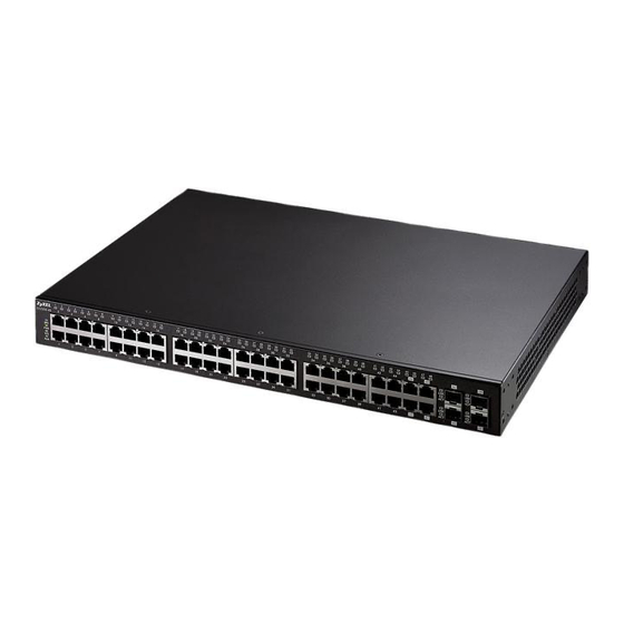
Switch. 1.1 Introduction The GS2200-48 is a stand-alone layer 2 Gigabit Ethernet (GbE) switch. It comes with 44 100/1000 Mbps Ethernet ports, 4 Dual Personality interfaces (each consisting of one RJ-45 Gigabit port and one slot for a mini-GBIC transceiver (SFP module) with one port active at a time) and two mini-GBIC transceivers for fiber- optic uplink connections. -
Page 24: High Performance Switching Example
Trunking can be used with copper cabling over relatively shorter distances than fiber-optic connections. Figure 2 High Performance Switching 1 Gbps Trunk Branch GS2200-48 User’s Guide... -
Page 25: Gigabit Ethernet To The Desktop
Ports in the same VLAN group share the same frame broadcast domain, thus increasing network performance by reducing broadcast traffic. VLAN groups can be modified at any time by adding, moving or changing ports without any re- cabling. GS2200-48 User’s Guide... -
Page 26: Ways To Manage The Switch
• Change the password. Use a password that’s not easy to guess and that consists of different types of characters, such as numbers and letters. • Write down the password and put it in a safe place. GS2200-48 User’s Guide... - Page 27 If you forget your password, you will have to reset the Switch to its factory default settings. If you backed up an earlier configuration file, you would not have to totally re-configure the Switch. You could simply restore your last configuration. GS2200-48 User’s Guide...
- Page 28 Chapter 1 Getting to Know Your Switch GS2200-48 User’s Guide...
-
Page 29: Hardware Installation And Connection
Attach the rubber feet to each corner on the bottom of the Switch. These rubber feet help protect the Switch from shock or vibration and ensure space between devices when stacking. Figure 5 Attaching Rubber Feet Note: Do NOT block the ventilation holes. Leave space between devices when stacking. GS2200-48 User’s Guide... -
Page 30: Mounting The Switch On A Rack
Switch. Figure 6 Attaching the Mounting Brackets Using a #2 Philips screwdriver, install the M3 flat head screws through the mounting bracket holes into the Switch. GS2200-48 User’s Guide... -
Page 31: Mounting The Switch On A Rack
Figure 7 Mounting the Switch on a Rack Using a #2 Philips screwdriver, install the M5 flat head screws through the mounting bracket holes into the rack. Repeat steps to attach the second mounting bracket on the other side of the rack. GS2200-48 User’s Guide... - Page 32 Chapter 2 Hardware Installation and Connection GS2200-48 User’s Guide...
-
Page 33: Hardware Overview
Connect these ports to high-bandwidth backbone network Ethernet 1000 switches using 1000Base-T compatible Category 5/5e/6 copper cables. Mbps RJ- 45 Ports 4 Mini- Use mini-GBIC transceivers in these slots for fiber-optic connections to GBIC backbone Ethernet switches. Slots GS2200-48 User’s Guide... -
Page 34: 1000Base-T Ports
Factor Pluggable (SFP) Transceiver MultiSource Agreement (MSA). See the SFF committee’s INF-8074i specification Rev 1.0 for details. You can change transceivers while the Switch is operating. You can use different transceivers to connect to Ethernet switches with different types of fiber-optic connectors. GS2200-48 User’s Guide... -
Page 35: Transceiver Installation
Press the transceiver firmly until it clicks into place. The Switch automatically detects the installed transceiver. Check the LEDs to verify that it is functioning properly. Figure 10 Installed Transceiver 3.1.3.2 Transceiver Removal Use the following steps to remove a mini GBIC transceiver (SFP module). GS2200-48 User’s Guide... -
Page 36: Rear Panel
• Two Mini-GBIC uplink slots (A) • An RS-232 management console port (B) • An RJ-45 out-of-band management port (C) • A connector for the backup power supply (D) • A connector for the power receptacle (E) Figure 13 Rear Panel GS2200-48 User’s Guide... -
Page 37: Power Connector
For local management, you can use a computer with terminal emulation software configured to the following parameters: • VT100 terminal emulation • 9600 bps • No parity, 8 data bits, 1 stop bit • No flow control GS2200-48 User’s Guide... -
Page 38: Leds
The link to a 100 Mbps Ethernet network is up. The link to an Ethernet network is down. Mini-GBIC Slot Green The port has a successful connection. No Ethernet device is connected to this port. Green Blinking The port is receiving or transmitting data. GS2200-48 User’s Guide... -
Page 39: Basic Configuration
Basic Configuration The Web Configurator (41) Initial Setup Example (51) System Status and Port Statistics (57) Basic Setting (63) -
Page 41: The Web Configurator
Type “http://” and the IP address of the Switch (for example, the default management IP address is 192.168.1.1 through an in-band (non-MGMT) port and 192.168.0.1 through the MGMT port) in the Location or Address field. Press [ENTER]. GS2200-48 User’s Guide... -
Page 42: The Status Screen
4.3 The Status Screen The Status screen is the first screen that displays when you access the web configurator. The following figure shows the navigating components of a web configurator screen. Figure 15 Web Configurator Home Screen (Status) GS2200-48 User’s Guide... - Page 43 E - Click this link to display web help pages. The help pages provide descriptions for all of the configuration screens. In the navigation panel, click a main link to reveal a list of submenu links. Table 4 Navigation Panel Sub-links Overview ADVANCED BASIC SETTING IP APPLICATION MANAGEMENT APPLICATION GS2200-48 User’s Guide...
- Page 44 Classifier Policy Rule Queuing Method VLAN Stacking Multicast (Status) Multicast Setting - IGMP Snooping VLAN - IGMP Filtering Profile - MVR -- Group Configuration Authentication and Accounting RADIUS Server Setup TACACS+ Server Setup Auth and Acct Setup GS2200-48 User’s Guide...
- Page 45 These static MAC addresses do not age out. Filtering This link takes you to a screen to set up filtering rules. Spanning Tree This link takes you to screens where you can configure the RSTP/MSTP Protocol to prevent network loops. GS2200-48 User’s Guide...
- Page 46 DSCP-to-IEEE802.1p mappings. DHCP This link takes you to screens where you can configure the DHCP settings. VRRP This link takes you to screens where you can configure redundant virtual router for your network. Management GS2200-48 User’s Guide...
-
Page 47: Change Your Password
4.3.1 Change Your Password After you log in for the first time, it is recommended you change the default administrator password. Click Management > Access Control > Logins to display the next screen. Figure 16 Change Administrator Login Password GS2200-48 User’s Guide... -
Page 48: Saving Your Configuration
Switch. 4.6 Resetting the Switch If you lock yourself (and others) from the Switch or forget the administrator password, you will need to reload the factory-default configuration file or reset the Switch back to the factory defaults. GS2200-48 User’s Guide... -
Page 49: Reload The Configuration File
FLASH: Intel 64M ZyNOS Version: V3.80(BPR.0)b4 | 6/9/2009 11:48:47 Press any key to enter debug mode within 3 seconds....... Enter Debug Mode GS2200-48> atlc Starting XMODEM upload (CRC mode)..CCCCCCCCCCCCCCCC Total 393216 bytes received. Erasing..............GS2200-48> atgo GS2200-48 User’s Guide... -
Page 50: Logging Out Of The Web Configurator
Figure 18 Web Configurator: Logout Screen 4.8 Help The web configurator’s online help has descriptions of individual screens and some supplementary information. Click the Help link from a web configurator screen to view an online help description of that screen. GS2200-48 User’s Guide... -
Page 51: Initial Setup Example
In the example network, since the RD network is already in the same IP interface as the Switch, you don’t need to create an IP interface for it. However, if you want to have the Sales network on a different routing domain, you need to create a GS2200-48 User’s Guide... - Page 52 Click Basic Setting and IP Setup in the navigation panel. Configure the related fields in the IP Setup screen. example For the Sales network, enter 192.168.2.1 as the IP address and 255.255.255.0 as the subnet mask. GS2200-48 User’s Guide...
-
Page 53: Configuring Dhcp Server Settings
Switch’s power is turned off. 5.1.3 Creating a VLAN VLANs confine broadcast frames to the VLAN group in which the port(s) belongs. You can do this with port-based VLAN or tagged static VLAN with fixed port members. GS2200-48 User’s Guide... - Page 54 Name field and enter 2 in the VLAN Group ID field for the VLAN2 network. example Note: The VLAN Group ID field in this screen and the VID field in the IP Setup screen refer to the same VLAN ID. GS2200-48 User’s Guide...
-
Page 55: Setting Port Vid
Setting link. Enter 2 in the PVID field for port 1 and click Apply to save your changes back to the run-time memory. Settings in the run-time example memory are lost when the Switch’s power is turned off. GS2200-48 User’s Guide... -
Page 56: Enabling Rip
In the Version field, select RIP-1 for the RIP packet format that is universally example supported. Click Apply to save your changes back to the run-time memory. Settings in the run-time memory are lost when the Switch’s power is turned off. GS2200-48 User’s Guide... -
Page 57: System Status And Port Statistics
Statistics This chapter describes the system status (web configurator home page) and port details screens. 6.1 Overview The home screen of the web configurator displays a port statistical summary with links to each port showing statistical details. GS2200-48 User’s Guide... -
Page 58: Port Status Summary
TxPkts This field shows the number of transmitted frames on this port. RxPkts This field shows the number of received frames on this port. Errors This field shows the number of received errors on this port. GS2200-48 User’s Guide... -
Page 59: Status: Port Details
Click a number in the Port column in the Status screen to display individual port statistics. Use this screen to check status and detailed performance data about an individual port on the Switch. Figure 23 Status: Port Details GS2200-48 User’s Guide... - Page 60 This field shows the number of 802.3x Pause packets received. Control This field shows the number of control packets received (including those with CRC error) but it does not include the 802.3x Pause packets. TX Collision The following fields display information on collisions while transmitting. GS2200-48 User’s Guide...
- Page 61 This field shows the number of packets (including bad packets) received 1518 that were between 1024 and 1518 octets in length. Giant This field shows the number of packets dropped because they were bigger than the maximum frame size. GS2200-48 User’s Guide...
- Page 62 Chapter 6 System Status and Port Statistics GS2200-48 User’s Guide...
-
Page 63: Basic Setting
Setup screen allows you to set up and configure global Switch features. The IP Setup screen allows you to configure a Switch IP address in each routing domain, subnet mask(s) and DNS (domain name server) for management purposes. GS2200-48 User’s Guide... -
Page 64: System Information
Address Switch. Hardware Monitor Temperature The Switch has temperature sensors that are capable of detecting and Unit reporting if the temperature rises above the threshold. You may choose the temperature unit (Centigrade or Fahrenheit) in this field. GS2200-48 User’s Guide... - Page 65 Normal indicates that the voltage is within an acceptable operating range at this point; otherwise Error is displayed. This field may also display Absent in the field corresponding to the backup power supply (BPS_12V), if the backup power supply is not in use. GS2200-48 User’s Guide...
-
Page 66: General Setup
Type the geographic location of your Switch. You can use up to 32 printable ASCII characters; spaces are allowed. Contact Type the name of the person in charge of this Switch. You can use up to Person's Name 32 printable ASCII characters; spaces are allowed. GS2200-48 User’s Guide... - Page 67 European Union you would select Last, Sunday, March and the last field depends on your time zone. In Germany for instance, you would select 2:00 because Germany's time zone is one hour ahead of GMT or UTC (GMT+1). GS2200-48 User’s Guide...
-
Page 68: Introduction To Vlans
With VLAN, all broadcasts are confined to a specific broadcast domain. Note: VLAN is unidirectional; it only governs outgoing traffic. Chapter 8 on page 79 for information on port-based and 802.1Q tagged VLANs. GS2200-48 User’s Guide... -
Page 69: Switch Setup Screen
Join message using GARP. Declarations are withdrawn by issuing a Leave message. A Leave All message terminates all registrations. GARP timers set declaration timeout values. See Section 8.1 on page 79 for more background information. GS2200-48 User’s Guide... - Page 70 Switch loses these changes if it is turned off or loses power, so use the Save link on the top navigation panel to save your changes to the non- volatile memory when you are done configuring. Cancel Click Cancel to begin configuring this screen afresh. GS2200-48 User’s Guide...
-
Page 71: Ip Setup
To change the IP address of the Switch in a routing domain, simply add a new routing domain entry with a different IP address in the same subnet. Figure 27 Basic Setting > IP Setup GS2200-48 User’s Guide... - Page 72 Cancel Click Cancel to reset the fields to your previous configuration. Index This field displays the index number of an entry. IP Address This field displays IP address of the Switch in the IP domain. GS2200-48 User’s Guide...
-
Page 73: Port Setup
Click Cancel to clear the Delete check boxes. 7.7 Port Setup Use this screen to configure Switch port settings.Click Basic Setting > Port Setup in the navigation panel to display the configuration screen. Figure 28 Basic Setting > Port Setup GS2200-48 User’s Guide... - Page 74 Back Pressure flow control is typically used in half duplex mode to send a "collision" signal to the sending port (mimicking a state of packet collision) causing the sending port to temporarily stop sending signals and resend later. Select Flow Control to enable it. GS2200-48 User’s Guide...
- Page 75 Switch loses these changes if it is turned off or loses power, so use the Save link on the top navigation panel to save your changes to the non- volatile memory when you are done configuring. Cancel Click Cancel to begin configuring this screen afresh. GS2200-48 User’s Guide...
- Page 76 Chapter 7 Basic Setting GS2200-48 User’s Guide...
-
Page 77: Advanced Setup
Advanced Setup VLAN (79) Static MAC Forward Setup (99) Filtering (103) Spanning Tree Protocol (105) Bandwidth Control (123) Broadcast Storm Control (127) Mirroring (129) Link Aggregation (131) Port Authentication (139) Port Security (145) Classifier (149) Policy Rule (157) Queuing Method (165) VLAN Stacking (169) Multicast (175) Authentication &... -
Page 79: Vlan
3 Bits 1 Bit 12 bits 8.1.1 Forwarding Tagged and Untagged Frames Each port on the Switch is capable of passing tagged or untagged frames. To forward a frame from an 802.1Q VLAN-aware switch to an 802.1Q VLAN-unaware GS2200-48 User’s Guide... -
Page 80: Automatic Vlan Registration
Please refer to the following table for common IEEE 802.1Q VLAN terminology. Table 15 IEEE 802.1Q VLAN Terminology VLAN TERM DESCRIPTION PARAMETER VLAN Type Permanent VLAN This is a static VLAN created manually. Dynamic VLAN This is a VLAN configured by a GVRP registration/ deregistration process. GS2200-48 User’s Guide... -
Page 81: Port Vlan Trunking
VLAN group tags. However, with VLAN Trunking enabled on a port(s) in each intermediary switch you only need to create VLAN groups in the end devices (A and B). C, D and E automatically GS2200-48 User’s Guide... -
Page 82: Select The Vlan Type
• sent to a group whether it has a VLAN tag or not. • blocked from a VLAN group regardless of its VLAN tag. You can also tag all outgoing frames (that were previously untagged) from a port with the specified VID. GS2200-48 User’s Guide... -
Page 83: Static Vlan Status
GVRP, static - added as a permanent entry or other - added in another way such as via Multicast VLAN Registration (MVR). Change Pages Click Previous or Next to show the previous/next screen if all status information cannot be seen in one screen. GS2200-48 User’s Guide... -
Page 84: Static Vlan Details
Multicast VLAN Registration (MVR). 8.5.3 Configure a Static VLAN Use this screen to configure and view 802.1Q VLAN parameters for the Switch. Section 8.1 on page 79 for more information on static VLAN. To configure a GS2200-48 User’s Guide... - Page 85 Use this row only if you want to make some settings the same for all ports. Use this row first to set the common settings and then make adjustments on a port-by-port basis. Note: Changes in this row are copied to all the ports as soon as you make them. GS2200-48 User’s Guide...
- Page 86 This field indicates whether the VLAN settings are enabled (Yes) or disabled (No). Name This field displays the descriptive name for this VLAN group. Delete Click Delete to remove the selected entry from the summary table. Cancel Click Cancel to clear the Delete check boxes. GS2200-48 User’s Guide...
-
Page 87: Configure Vlan Port Settings
Use this row only if you want to make some settings the same for all ports. Use this row first to set the common settings and then make adjustments on a port-by-port basis. Note: Changes in this row are copied to all the ports as soon as you make them. GS2200-48 User’s Guide... -
Page 88: Subnet Based Vlans
VLAN with priority 5 and VID of 200 for traffic received from IP subnet 192.168.1.0/24 (video services). Lastly, you can configure VLAN with priority 3 and VID of 300 for traffic received from IP subnet 10.1.1.0/24 (data GS2200-48 User’s Guide... -
Page 89: Configuring Subnet Based Vlan
Internet Untagged Frames 10.1.1.0/24 172.16.1.0/24 192.168.1.0/24 VID = 300 VID = 100 VID = 200 8.7 Configuring Subnet Based VLAN Click Subnet Based VLAN in the VLAN Port Setting screen to display the configuration screen as shown. GS2200-48 User’s Guide... - Page 90 1’s together. Take “255.255.255.0” for example. 255 converts to eight 1s in binary. There are three 255s, so add three eights together and you get the bit number (24). GS2200-48 User’s Guide...
-
Page 91: Protocol Based Vlans
3 for ARP traffic received on port 1, 2 and 3. You can also have a protocol based VLAN B with priority 2 for Apple Talk traffic received on port 6 and 7. All upstream ARP traffic from port 1, 2 and 3 will be grouped together, and all upstream Apple GS2200-48 User’s Guide... -
Page 92: Configuring Protocol Based Vlan
Figure 37 Protocol Based VLAN Application Example 8.9 Configuring Protocol Based VLAN Click Protocol Based VLAN in the VLAN Port Setting screen to display the configuration screen as shown. Figure 38 Advanced Application > VLAN > VLAN Port Setting > Protocol Based VLAN GS2200-48 User’s Guide... - Page 93 This field shows the priority which is assigned to frames belonging to this protocol based VLAN. Delete Click this to delete the protocol based VLANs which you marked for deletion. Cancel Click Cancel to begin configuring this screen afresh. GS2200-48 User’s Guide...
-
Page 94: Create An Ip-Based Vlan Example
To add more ports to this protocol based VLAN. Click the index number of the protocol based VLAN entry. Click 1 Change the value in the Port field to the next port you want to add. Click Add. GS2200-48 User’s Guide... -
Page 95: Port-Based Vlan Setup
Connected or Port Isolated from the drop-down list depending on your VLAN and VLAN security requirements. If VLAN members need to communicate directly with each other, then select All Connected. Select Port Isolated if you want to restrict users from communicating directly. Click Apply to save your settings. GS2200-48 User’s Guide... - Page 96 Chapter 8 VLAN The following screen shows users on a port-based, all-connected VLAN configuration. Figure 40 Advanced Application > VLAN > Port Based VLAN Setup (All Connected) GS2200-48 User’s Guide...
- Page 97 Chapter 8 VLAN The following screen shows users on a port-based, port-isolated VLAN configuration. Figure 41 Advanced Application > VLAN: Port Based VLAN Setup (Port Isolation) GS2200-48 User’s Guide...
- Page 98 Switch loses these changes if it is turned off or loses power, so use the Save link on the top navigation panel to save your changes to the non- volatile memory when you are done configuring. Cancel Click Cancel to begin configuring this screen afresh. GS2200-48 User’s Guide...
-
Page 99: Static Mac Forward Setup
Static MAC address forwarding together with port security allows only computers in the MAC address table on a port to access the Switch. See Chapter 17 on page for more information on port security. GS2200-48 User’s Guide... - Page 100 MAC address-forwarding rule. MAC Address This field displays the MAC address that will be forwarded and the VLAN identification number to which the MAC address belongs. This field displays the ID number of the VLAN group. GS2200-48 User’s Guide...
- Page 101 This field displays the port where the MAC address shown in the next field will be forwarded. Delete Click Delete to remove the selected entry from the summary table. Cancel Click Cancel to clear the Delete check boxes. GS2200-48 User’s Guide...
- Page 102 Chapter 9 Static MAC Forward Setup GS2200-48 User’s Guide...
-
Page 103: Filtering
Make sure to select this check box to activate your rule. You may temporarily deactivate a rule without deleting it by deselecting this check box. Name Type a descriptive name (up to 32 printable ASCII characters) for this rule. This is for identification only. GS2200-48 User’s Guide... - Page 104 Discard both will be displayed. Delete Check the rule(s) that you want to remove in the Delete column and then click the Delete button. Cancel Click Cancel to clear the selected checkbox(es) in the Delete column. GS2200-48 User’s Guide...
-
Page 105: Spanning Tree Protocol
Both RSTP and STP flush unwanted learned addresses from the filtering database. In RSTP, the port states are Discarding, Learning, and Forwarding. Note: In this user’s guide, “STP” refers to both STP and RSTP. 11.1.1 STP Terminology The root bridge is the base of the spanning tree. GS2200-48 User’s Guide... -
Page 106: How Stp Works
Hello BPDU after a predefined interval (Max Age), the bridge assumes that the link to the root bridge is down. This bridge then initiates negotiations with other bridges to reconfigure the network to re-establish a valid network topology. GS2200-48 User’s Guide... -
Page 107: Stp Port States
11.1.4.1 MSTP Network Example The following figure shows a network example where two VLANs are configured on the two switches. If the switches are using STP or RSTP, the link for VLAN 2 will be GS2200-48 User’s Guide... -
Page 108: Mst Region
MST region. When BPDUs enter an MST region, external path cost (of paths outside this region) is increased by one. Internal path cost (of paths within this region) is increased by one when BPDUs traverse the region. GS2200-48 User’s Guide... -
Page 109: Mst Instance
STP/RSTP. The CIST is the default MST instance (MSTID 0). Any VLANs that are not members of an MST instance are members of the CIST. In an MSTP-enabled network, there is only one CIST that runs between MST regions GS2200-48 User’s Guide... -
Page 110: Spanning Tree Protocol Status Screen
This screen differs depending on which STP mode (RSTP or MSTP) you configure on the Switch. This screen is described in detail in the section that follows the configuration section for each STP mode. Click Configuration to activate one of the STP standards on the Switch. GS2200-48 User’s Guide... -
Page 111: Spanning Tree Configuration
Switch loses these changes if it is turned off or loses power, so use the Save link on the top navigation panel to save your changes to the non- volatile memory when you are done configuring. Cancel Click Cancel to begin configuring this screen afresh. GS2200-48 User’s Guide... -
Page 112: Configure Rapid Spanning Tree Protocol
Use this screen to configure RSTP settings, see Section 11.1 on page 105 for more information on RSTP. Click RSTP in the Advanced Application > Spanning Tree Protocol screen. Figure 50 Advanced Application > Spanning Tree Protocol > RSTP GS2200-48 User’s Guide... - Page 113 Use this row only if you want to make some settings the same for all ports. Use this row first to set the common settings and then make adjustments on a port-by-port basis. Note: Changes in this row are copied to all the ports as soon as you make them. GS2200-48 User’s Guide...
-
Page 114: Rapid Spanning Tree Protocol Status
See Section 11.1 on page 105 more information on RSTP. Note: This screen is only available after you activate RSTP on the Switch. Figure 51 Advanced Application > Spanning Tree Protocol > Status: RSTP GS2200-48 User’s Guide... - Page 115 Switch must communicate with the root of the Spanning Tree. Topology This is the number of times the spanning tree has been reconfigured. Changed Times Time Since Last This is the time since the spanning tree was last reconfigured. Change GS2200-48 User’s Guide...
-
Page 116: Configure Multiple Spanning Tree Protocol
11.6 Configure Multiple Spanning Tree Protocol To configure MSTP, click MSTP in the Advanced Application > Spanning Tree Protocol screen. See Section 11.1.4 on page 107 for more information on MSTP. Figure 52 Advanced Application > Spanning Tree Protocol > MSTP GS2200-48 User’s Guide... - Page 117 Click Cancel to begin configuring this screen afresh. Instance Use this section to configure MSTI (Multiple Spanning Tree Instance) settings. Instance Enter the number you want to use to identify this MST instance on the Switch. The Switch supports instance numbers 0-16. GS2200-48 User’s Guide...
- Page 118 This field displays the ID of an MST instance. VLAN This field displays the VID (or VID ranges) to which the MST instance is mapped. Active Port This field display the ports configured to participate in the MST instance. GS2200-48 User’s Guide...
-
Page 119: Multiple Spanning Tree Protocol Status
See Section 11.1.4 on page 107 more information on MSTP. Note: This screen is only available after you activate MSTP on the Switch. Figure 53 Advanced Application > Spanning Tree Protocol > Status: MSTP GS2200-48 User’s Guide... - Page 120 This Switch may also be the root bridge. Bridge ID This is the unique identifier for this bridge, consisting of bridge priority plus MAC address. This ID is the same for Root and Our Bridge if the Switch is the root switch. GS2200-48 User’s Guide...
- Page 121 This is the path cost from the root port in this MST instance to the regional root switch. Port ID This is the priority and number of the port on the Switch through which this Switch must communicate with the root of the MST instance. GS2200-48 User’s Guide...
- Page 122 Chapter 11 Spanning Tree Protocol GS2200-48 User’s Guide...
-
Page 123: Bandwidth Control
CIR will be marked for drop. Note: The CIR should be less than the PIR. Note: The sum of CIRs cannot be greater than or equal to the uplink bandwidth. GS2200-48 User’s Guide... -
Page 124: Bandwidth Control Setup
The commit rate should be less than the peak rate. The sum of commit rates cannot be greater than or equal to the uplink bandwidth. Active Select this check box to activate peak rate limits on this port. GS2200-48 User’s Guide... - Page 125 Switch loses these changes if it is turned off or loses power, so use the Save link on the top navigation panel to save your changes to the non- volatile memory when you are done configuring. Cancel Click Cancel to begin configuring this screen afresh. GS2200-48 User’s Guide...
- Page 126 Chapter 12 Bandwidth Control GS2200-48 User’s Guide...
-
Page 127: Broadcast Storm Control
DLF packets in your network. You can specify limits for each packet type on each port. Click Advanced Application > Broadcast Storm Control in the navigation panel to display the screen as shown next. Figure 55 Advanced Application > Broadcast Storm Control GS2200-48 User’s Guide... - Page 128 Switch loses these changes if it is turned off or loses power, so use the Save link on the top navigation panel to save your changes to the non- volatile memory when you are done configuring. Cancel Click Cancel to begin configuring this screen afresh. GS2200-48 User’s Guide...
-
Page 129: Mirroring
Click Advanced Application > Mirroring in the navigation panel to display the Mirroring screen. Use this screen to select a monitor port and specify the traffic flow to be copied to the monitor port. Figure 56 Advanced Application > Mirroring GS2200-48 User’s Guide... - Page 130 Switch loses these changes if it is turned off or loses power, so use the Save link on the top navigation panel to save your changes to the non-volatile memory when you are done configuring. Cancel Click Cancel to begin configuring this screen afresh. GS2200-48 User’s Guide...
-
Page 131: Link Aggregation
The IEEE 802.3ad standard describes the Link Aggregation Control Protocol (LACP) for dynamically creating and managing trunk groups. When you enable LACP link aggregation on a port, the port can automatically negotiate with the ports at the remote end of a link to establish trunk groups. GS2200-48 User’s Guide... -
Page 132: Link Aggregation Id
Link Aggregation Status screen displays by default. See Section 15.1 on page for more information. Figure 57 Advanced Application > Link Aggregation Status Port Priority and Port Number are 0 as it is the aggregator ID for the trunk group, not the individual port. GS2200-48 User’s Guide... - Page 133 This field displays how these ports were added to the trunk group. It displays: • Static - if the ports are configured as static members of a trunk group. • LACP - if the ports are configured to join a trunk group via LACP. GS2200-48 User’s Guide...
-
Page 134: Link Aggregation Setting
The field identifies the link aggregation group, that is, one logical link containing multiple ports. Active Select this option to activate a trunk group. Port This field displays the port number. Group Select the trunk group to which a port belongs. GS2200-48 User’s Guide... -
Page 135: Link Aggregation Control Protocol
Click in the Advanced Application > Link Aggregation > Link Aggregation Setting > LACP to display the screen shown next. See Section 15.2 on page 131 for more information on dynamic link aggregation. Figure 59 Advanced Application > Link Aggregation > Link Aggregation Setting > LACP GS2200-48 User’s Guide... -
Page 136: Static Trunking Example
Save link on the top navigation panel to save your changes to the non- volatile memory when you are done configuring. Cancel Click Cancel to begin configuring this screen afresh. 15.6 Static Trunking Example This example shows you how to create a static port trunk group for ports 2-5. GS2200-48 User’s Guide... - Page 137 > Link Aggregation Setting. In this screen activate trunking group T1 and select the ports that should belong to this group as shown in the figure below. Click Apply when you are done. Figure 61 Trunking Example - Configuration Screen example GS2200-48 User’s Guide...
- Page 138 Chapter 15 Link Aggregation Your trunk group 1 (T1) configuration is now complete; you do not need to go to any additional screens. GS2200-48 User’s Guide...
-
Page 139: Port Authentication
When the client provides the login credentials, the Switch sends an authentication At the time of writing, IEEE 802.1x is not supported by all operating systems. See your operating system documentation. If your operating system does not support 802.1x, then you may need to install 802.1x client software. GS2200-48 User’s Guide... -
Page 140: Mac Authentication
MAC authentication works in a very similar way to IEEE 802.1x authentication. The main difference is that the Switch does not prompt the client for login credentials. The login credentials are based on the source MAC address of the GS2200-48 User’s Guide... -
Page 141: Port Authentication Configuration
Auth and Acct > Radius Server Setup screen. To activate a port authentication method, click Advanced Application > Port Authentication in the navigation panel. Select a port authentication method in the screen that appears. Figure 64 Advanced Application > Port Authentication GS2200-48 User’s Guide... -
Page 142: Activate Ieee 802.1X Security
Note: Changes in this row are copied to all the ports as soon as you make them. Active Select this checkbox to permit 802.1x authentication on this port. You must first allow 802.1x authentication on the Switch before configuring it on each port. GS2200-48 User’s Guide... -
Page 143: Activate Mac Authentication
Click Cancel to begin configuring this screen afresh. 16.2.2 Activate MAC Authentication Use this screen to activate MAC authentication. In the Port Authentication screen click MAC Authentication to display the configuration screen as shown. Figure 66 Advanced Application > Port Authentication > MAC Authentication GS2200-48 User’s Guide... - Page 144 Switch loses these changes if it is turned off or loses power, so use the Save link on the top navigation panel to save your changes to the non- volatile memory when you are done configuring. Cancel Click Cancel to begin configuring this screen afresh. GS2200-48 User’s Guide...
-
Page 145: Port Security
MAC address(es) for a port. It is not recommended you disable port security together with MAC address learning as this will result in many broadcasts. By default, MAC address learning is still enabled even though the port security is not activated. GS2200-48 User’s Guide... -
Page 146: Port Security Setup
Switch forwards packets whose MAC address(es) is in the MAC address table on this port. Packets with no matching MAC address(es) are dropped. Clear this check box to disable the port security feature. The Switch forwards all packets on this port. GS2200-48 User’s Guide... - Page 147 Switch loses these changes if it is turned off or loses power, so use the Save link on the top navigation panel to save your changes to the non- volatile memory when you are done configuring. Cancel Click Cancel to begin configuring this screen afresh. GS2200-48 User’s Guide...
- Page 148 Chapter 17 Port Security GS2200-48 User’s Guide...
-
Page 149: Classifier
Use the Classifier screen to define the classifiers. After you define the classifier, you can specify actions (or policy) to act upon the traffic that matches the rules. To configure policy rules, refer to Chapter 19 on page 157. GS2200-48 User’s Guide... - Page 150 Ethernet II tagged and Ethernet II untagged. A value of 802.3 indicates that the packets are formatted according to the IEEE 802.3 standards. A value of Ethernet II indicates that the packets are formatted according to RFC 894, Ethernet II encapsulation. GS2200-48 User’s Guide...
- Page 151 Note: You must select either UDP or TCP in the IP Protocol field before Number you configure the socket numbers. Select Any to apply the rule to all TCP/UDP protocol port numbers or select the second option and enter a TCP/UDP protocol port number. Destination GS2200-48 User’s Guide...
-
Page 152: Viewing And Editing Classifier Configuration
Classifier screen. To change the settings of a rule, click a number in the Index field. Note: When two rules conflict with each other, a higher layer rule has priority over a lower layer rule. Figure 69 Advanced Application > Classifier: Summary Table GS2200-48 User’s Guide... - Page 153 The following table shows some common protocol types and the corresponding protocol number. Refer to http://www.iana.org/assignments/ protocol-numbers for a complete list. Table 46 Common IP Protocol Types and Protocol Numbers PROTOCOL PROTOCOL TYPE NUMBER ICMP L2TP GS2200-48 User’s Guide...
- Page 154 Chapter 18 Classifier Some of the most common IP ports are: Table 47 Common TCP and UDP Port Numbers PORT PORT NAME NUMBER Telnet SMTP HTTP POP3 GS2200-48 User’s Guide...
-
Page 155: Classifier Example
Figure 70 Classifier: Example example After you have configured a classifier, you can configure a policy to define action(s) on the classified traffic flow. See Chapter 19 on page 157 for information on configuring a policy rule. GS2200-48 User’s Guide... - Page 156 Chapter 18 Classifier GS2200-48 User’s Guide...
-
Page 157: Policy Rule
DS field. DSCP is backward compatible with the three precedence bits in the ToS octet so that non-DiffServ compliant, ToS-enabled network device will not conflict with the DSCP mapping. DSCP (6 bits) Unused (2 bits) GS2200-48 User’s Guide... -
Page 158: Configuring Policy Rules
DSCP values and the configured policies. 19.2 Configuring Policy Rules You must first configure a classifier in the Classifier screen. Refer to Section 18.2 on page 149 for more information. GS2200-48 User’s Guide... - Page 159 Chapter 19 Policy Rule Click Advanced Applications > Policy Rule in the navigation panel to display the screen as shown. Figure 71 Advanced Application > Policy Rule GS2200-48 User’s Guide...
- Page 160 Select Send the packet to priority queue to put the packets in the designated queue. Select Replace the 802.1 priority field with the IP TOS value to replace the packet’s 802.1 priority field with the value you set in the TOS field. GS2200-48 User’s Guide...
-
Page 161: Viewing And Editing Policy Configuration
To view a summary of the classifier configuration, scroll down to the summary table at the bottom of the Policy screen. To change the settings of a rule, click a number in the Index field. Figure 72 Advanced Application > Policy Rule: Summary Table GS2200-48 User’s Guide... - Page 162 This field displays the name you have assigned to this policy. Classifier( This field displays the name(s) of the classifier to which this policy applies. Delete Click Delete to remove the selected entry from the summary table. Cancel Click Cancel to clear the Delete check boxes. GS2200-48 User’s Guide...
-
Page 163: Policy Example
The figure below shows an example Policy screen where you configure a policy to limit bandwidth and discard out-of-profile traffic on a traffic flow classified using the Example classifier (refer to Section 18.4 on page 155). Figure 73 Policy Example example GS2200-48 User’s Guide... - Page 164 Chapter 19 Policy Rule GS2200-48 User’s Guide...
-
Page 165: Queuing Method
Queues with larger weights get more guaranteed bandwidth than queues with smaller weights. This queuing mechanism is highly efficient in that it divides any available bandwidth across the GS2200-48 User’s Guide... -
Page 166: Weighted Round Robin Scheduling (Wrr)
Queues with larger weights get more service than queues with smaller weights. This queuing mechanism is highly efficient in that it divides any available bandwidth across the different traffic queues and returns to queues that have not yet emptied. GS2200-48 User’s Guide... -
Page 167: Configuring Queuing
Use this row only if you want to make some settings the same for all ports. Use this row first to set the common settings and then make adjustments on a port-by-port basis. Note: Changes in this row are copied to all the ports as soon as you make them. GS2200-48 User’s Guide... - Page 168 Switch loses these changes if it is turned off or loses power, so use the Save link on the top navigation panel to save your changes to the non-volatile memory when you are done configuring. Cancel Click Cancel to begin configuring this screen afresh. GS2200-48 User’s Guide...
-
Page 169: Vlan Stacking
(SPN) customers with VPN tunnels between their head offices and branch offices respectively. Both have an identical VLAN tag for their VLAN group. The service provider can separate these two VLANs within its network by adding tag 37 to GS2200-48 User’s Guide... -
Page 170: Vlan Stacking Port Roles
All VLANs belonging to a customer can be aggregated into a single service provider's VLAN (using the outer VLAN tag defined by the Service Provider’s (SP) VLAN ID (VID)). Note: Static VLAN Tx Tagging MUST be enabled on a port where you choose Tunnel Port. GS2200-48 User’s Guide... -
Page 171: Vlan Tag Format
VID is the VLAN ID. SP VID is the VID for the second (service provider’s) VLAN tag. 21.3.1 Frame Format The frame format for an untagged Ethernet frame, a single-tagged 802.1Q frame (customer) and a “double-tagged” 802.1Q frame (service provider) is shown next. GS2200-48 User’s Guide... - Page 172 FCS Double- Etype tagged frame Table 53 802.1Q Frame Destination Address Priority 802.1p Priority Source Address Len/ Length and type of Ethernet Etype frame (SP)TPI (Service Provider) Tag Protocol Data Frame data IDentifier VLAN ID Frame Check Sequence GS2200-48 User’s Guide...
-
Page 173: Configuring Vlan Stacking
Use this row only if you want to make some settings the same for all ports. Use this row first to set the common settings and then make adjustments on a port- by-port basis. Note: Changes in this row are copied to all the ports as soon as you make them. GS2200-48 User’s Guide... - Page 174 Save link on the top navigation panel to save your changes to the non-volatile memory when you are done configuring. Cancel Click Cancel to begin configuring this screen afresh. GS2200-48 User’s Guide...
-
Page 175: Multicast
(such as content information distribution) based on service plans and types of subscription. You can set the Switch to filter the multicast group join reports on a per-port basis by configuring an IGMP filtering profile and associating the profile to a port. GS2200-48 User’s Guide... -
Page 176: Igmp Snooping
Figure 77 Advanced Application > Multicast The following table describes the labels in this screen. Table 55 Multicast Status LABEL DESCRIPTION Index This is the index number of the entry. This field displays the multicast VLAN ID. GS2200-48 User’s Guide... -
Page 177: Multicast Setting
22.3 Multicast Setting Click Advanced Applications > Multicast > Multicast Setting link to display the screen as shown. See Section 22.1 on page 175 for more information on multicasting. Figure 78 Advanced Application > Multicast > Multicast Setting GS2200-48 User’s Guide... - Page 178 IGMP version 2 leave message is received on this port. Select this option if there is only one host connected to this port. Group Limited Select this option to limit the number of multicast groups this port is allowed to join. GS2200-48 User’s Guide...
-
Page 179: Igmp Snooping Vlan
Cancel Click Cancel to begin configuring this screen afresh. 22.4 IGMP Snooping VLAN Click Advanced Applications > Multicast in the navigation panel. Click the Multicast Setting link and then the IGMP Snooping VLAN link to display the GS2200-48 User’s Guide... - Page 180 Click Cancel to begin configuring this screen afresh. VLAN Use this section of the screen to add VLANs upon which the Switch is to perform IGMP snooping. Name Enter the descriptive name of the VLAN for identification purposes. GS2200-48 User’s Guide...
-
Page 181: Igmp Filtering Profile
(in the Multicast Setting screen). Clients connected to those ports are then able to join the multicast groups specified in the profile. Each port can be assigned a single profile. A profile can be assigned to multiple ports. GS2200-48 User’s Guide... - Page 182 Click Clear to clear the fields to the factory defaults. Profile Name This field displays the descriptive name of the profile. Start Address This field displays the start of the multicast address range. End Address This field displays the end of the multicast address range. GS2200-48 User’s Guide...
-
Page 183: Mvr Overview
In MVR, a source port is a port on the Switch that can send and receive multicast traffic in a multicast VLAN while a receiver port can only receive multicast traffic. Once configured, the Switch maintains a forwarding table that matches the multicast stream to the associated multicast group. GS2200-48 User’s Guide... -
Page 184: Mvr Modes
Switch). If there is another subscriber device connected to this port in the same subscriber VLAN, the receiving port will still be on the list of forwarding destination for the multicast traffic. Otherwise, the Switch removes the receiver port from the forwarding table. Figure 82 MVR Multicast Television Example GS2200-48 User’s Guide... -
Page 185: General Mvr Configuration
Select this check box to enable MVR to allow one single multicast VLAN to be shared among different subscriber VLANs on the network. Name Enter a descriptive name (up to 32 printable ASCII characters) for identification purposes. GS2200-48 User’s Guide... - Page 186 This field displays the priority level. Delete To delete a multicast VLAN(s), select the rule(s) that you want to remove in the Delete column, then click the Delete button. Cancel Click Cancel to clear the Delete check boxes. GS2200-48 User’s Guide...
-
Page 187: Mvr Group Configuration
Enter the same IP address as the Start Address field if you want to configure only one IP address for a multicast group. Refer to Section 22.1.1 on page 175 for more information on IP multicast addresses. GS2200-48 User’s Guide... -
Page 188: Mvr Configuration Example
VID 200 to receive multicast traffic (the News and Movie channels) from the remote streaming media server, S. Computers A, B and C in VLAN 1 are able to receive the traffic. Figure 85 MVR Configuration Example GS2200-48 User’s Guide... - Page 189 Figure 86 MVR Configuration Example example To set the Switch to forward the multicast group traffic to the subscribers, configure multicast group settings in the Group Configuration screen. The GS2200-48 User’s Guide...
- Page 190 Chapter 22 Multicast following figure shows an example where two multicast groups (News and Movie) are configured for the multicast VLAN 200. Figure 87 MVR Group Configuration Example example Figure 88 MVR Group Configuration Example example GS2200-48 User’s Guide...
-
Page 191: Authentication & Accounting
The external servers that perform authentication, authorization and accounting functions are known as AAA servers. The Switch supports RADIUS (Remote Authentication Dial-In User Service, see Section 23.1.2 on page 192) and TACACS+ (Terminal Access Controller Access-Control System Plus, see Section GS2200-48 User’s Guide... -
Page 192: Local User Accounts
(the Switch) and the TACACS server is encrypted. 23.2 Authentication and Accounting Screens To enable authentication, accounting or both on the Switch. First, configure your authentication server settings (RADIUS, TACACS+ or both) and then set up the authentication priority and accounting settings. GS2200-48 User’s Guide... -
Page 193: Radius Server Setup
RADIUS servers. Click on the RADIUS Server Setup link in the Authentication and Accounting screen to view the screen as shown. Figure 91 Advanced Application > Auth and Acct > RADIUS Server Setup GS2200-48 User’s Guide... - Page 194 Enter the IP address of an external RADIUS accounting server in dotted decimal notation. UDP Port The default port of a RADIUS accounting server for accounting is 1813. You need not change this value unless your network administrator instructs you to do so. GS2200-48 User’s Guide...
-
Page 195: Tacacs+ Server Setup
TACACS+ servers. Click on the TACACS+ Server Setup link in the Authentication and Accounting screen to view the screen as shown. Figure 92 Advanced Application > Auth and Acct > TACACS+ Server Setup GS2200-48 User’s Guide... - Page 196 Enter the IP address of an external TACACS+ accounting server in dotted decimal notation. TCP Port The default port of a TACACS+ accounting server is 49. You need not change this value unless your network administrator instructs you to do GS2200-48 User’s Guide...
-
Page 197: Authentication And Accounting Setup
Use this screen to configure authentication and accounting settings on the Switch. Click on the Auth and Acct Setup link in the Authentication and Accounting screen to view the screen as shown. Figure 93 Advanced Application > Auth and Acct > Auth and Acct Setup GS2200-48 User’s Guide... - Page 198 Use this section to configure accounting settings on the Switch. Update Period This is the amount of time in minutes before the Switch sends an update to the accounting server. This is only valid if you select the start-stop option for the Exec or Dot1x entries. GS2200-48 User’s Guide...
-
Page 199: Vendor Specific Attribute
RFC 2865 standard specifies a method for sending vendor-specific information between a RADIUS server and a network access device (for example, the Switch). A company can create Vendor Specific Attributes (VSAs) to expand the functionality of a RADIUS server. GS2200-48 User’s Guide... - Page 200 The VSAs are composed of the following: • Vendor-ID: An identification number assigned to the company by the IANA (Internet Assigned Numbers Authority). ZyXEL’s vendor ID is 890. • Vendor-Type: A vendor specified attribute, identifying the setting you want to modify.
-
Page 201: Tunnel Protocol Attribute
Switch. In cases where the attribute has a specific format associated with it, the format is specified. 23.3.1 Attributes Used for Authentication The following sections list the attributes sent from the Switch to the RADIUS server when performing authentication. 23.3.1.1 Attributes Used for Authenticating Privilege Access User-Name GS2200-48 User’s Guide... -
Page 202: Attributes Used For Accounting
The following sections list the attributes sent from the Switch to the RADIUS server when performing authentication. 23.3.2.1 Attributes Used for Accounting System Events NAS-IP-Address NAS-Identifier Acct-Status-Type Acct-Session-ID - The format of Acct-Session-Id is date+time+8-digit sequential number, for example, 2007041917210300000001. (date: 2007/04/19, time: 17:21:03, serial number: 00000001) Acct-Delay-Time GS2200-48 User’s Guide... - Page 203 23.3.2.3 Attributes Used for Accounting IEEE 802.1x Events The attributes are listed in the following table along with the time of the session they are sent: Table 69 RADIUS Attributes - Exec Events via Console ATTRIBUTE START INTERIM-UPDATE STOP User-Name NAS-IP-Address GS2200-48 User’s Guide...
- Page 204 Chapter 23 Authentication & Accounting Table 69 RADIUS Attributes - Exec Events via Console ATTRIBUTE START INTERIM-UPDATE STOP NAS-Port Class Called-Station-Id Calling-Station-Id NAS-Identifier NAS-Port-Type Acct-Status-Type Acct-Delay-Time Acct-Session-Id Acct-Authentic Acct-Input-Octets Acct-Output-Octets Acct-Session-Time Acct-Input-Packets Acct-Output-Packets Acct-Terminate-Cause Acct-Input-Gigawords Acct-Output- Gigawords GS2200-48 User’s Guide...
-
Page 205: Ip Source Guard
• ARP inspection. Use this to filter unauthorized ARP packets on the network. If you want to use dynamic bindings to filter unauthorized ARP packets (typical implementation), you have to enable DHCP snooping before you enable ARP inspection. GS2200-48 User’s Guide... -
Page 206: Dhcp Snooping Overview
The DHCP snooping database maintains the dynamic bindings for DHCP snooping and ARP inspection in a file on an external TFTP server. If you set up the DHCP snooping database, the Switch can reload the dynamic bindings from the DHCP snooping database after the Switch restarts. GS2200-48 User’s Guide... -
Page 207: Configuring Dhcp Snooping
(Chapter 29 on page 249). 24.1.1.4 Configuring DHCP Snooping Follow these steps to configure DHCP snooping on the Switch. Enable DHCP snooping on the Switch. Enable DHCP snooping on each VLAN, and configure DHCP relay option 82. GS2200-48 User’s Guide... -
Page 208: Arp Inspection Overview
These MAC address filters are different than regular MAC address filters (Chapter 10 on page 103). • They are stored only in volatile memory. • They do not use the same space in memory that regular MAC address filters use. GS2200-48 User’s Guide... -
Page 209: Ip Source Guard
Use this screen to look at the current bindings for DHCP snooping and ARP inspection. Bindings are used by DHCP snooping and ARP inspection to distinguish between authorized and unauthorized packets in the network. The Switch learns GS2200-48 User’s Guide... -
Page 210: Ip Source Guard Static Binding
Static bindings are uniquely identified by the MAC address and VLAN ID. Each MAC address and VLAN ID can only be in one static binding. If you try to create a static binding with the same MAC address and VLAN ID as an existing static binding, the GS2200-48 User’s Guide... - Page 211 This field displays how long the binding is valid. Type This field displays how the Switch learned the binding. static: This binding was learned from information provided manually by an administrator. VLAN This field displays the source VLAN ID in the binding. GS2200-48 User’s Guide...
- Page 212 This field displays the port number in the binding. If this field is blank, the binding applies to all ports. Delete Select this, and click Delete to remove the specified entry. Cancel Click this to clear the Delete check boxes above. GS2200-48 User’s Guide...
-
Page 213: Dhcp Snooping
Chapter 24 IP Source Guard 24.4 DHCP Snooping Use this screen to look at various statistics about the DHCP snooping database. To open this screen, click Advanced Application > IP Source Guard > DHCP Snooping. GS2200-48 User’s Guide... - Page 214 Chapter 24 IP Source Guard Figure 98 DHCP Snooping GS2200-48 User’s Guide...
- Page 215 DHCP snooping database for any reason. Startup failures This field displays the number of times the Switch could not create or read the DHCP snooping database when the Switch started up or a new URL is configured for the DHCP snooping database. GS2200-48 User’s Guide...
- Page 216 Switch already had a binding with the same MAC address and VLAN ID. Invalid interfaces This field displays the number of bindings the Switch has ignored because the port number was a trusted interface or does not exist anymore. GS2200-48 User’s Guide...
-
Page 217: Dhcp Snooping Configure
TFTP server so that they are still available after a restart. To open this screen, click Advanced Application > IP Source Guard > DHCP Snooping > Configure. Figure 99 DHCP Snooping Configure GS2200-48 User’s Guide... - Page 218 If there is a conflict, the Switch keeps the dynamic binding in volatile memory and updates the Binding collisions counter in the DHCP Snooping screen (Section 24.4 on page 213). GS2200-48 User’s Guide...
-
Page 219: Dhcp Snooping Port Configure
You can also specify the maximum number for DHCP packets that each port (trusted or untrusted) can receive each second. To open this screen, click Advanced Application > IP Source Guard > DHCP Snooping > Configure > Port. Figure 100 DHCP Snooping Port Configure GS2200-48 User’s Guide... -
Page 220: Dhcp Snooping Vlan Configure
Use this screen to enable DHCP snooping on each VLAN and to specify whether or not the Switch adds DHCP relay agent option 82 information (Chapter 29 on page 249) to DHCP requests that the Switch relays to a DHCP server for each VLAN. To GS2200-48 User’s Guide... - Page 221 DHCP VLAN, if specified, or VLAN. You can configure the system name in the General Setup screen. See Chapter 7 on page 63. You can specify the DHCP VLAN in the DHCP Snooping Configure screen. See Section 24.5 on page 217. GS2200-48 User’s Guide...
-
Page 222: Arp Inspection Status
Port This field displays the source port of the discarded ARP packet. Expiry (sec) This field displays how long (in seconds) the MAC address filter remains in the Switch. You can also delete the record manually (Delete). GS2200-48 User’s Guide... -
Page 223: Arp Inspection Vlan Status
Select this to look at all the VLANs in a specific range in the section below. Then, enter the lowest VLAN ID (Start VID) and the highest VLAN ID (End VID) you want to look at. Apply Click this to display the specified range of VLANs in the section below. GS2200-48 User’s Guide... -
Page 224: Arp Inspection Log Status
Index This field displays a sequential number for each log message. Port This field displays the source port of the ARP packet. This field displays the source VLAN ID of the ARP packet. GS2200-48 User’s Guide... -
Page 225: Arp Inspection Configure
This field displays when the log message was generated. 24.7 ARP Inspection Configure Use this screen to enable ARP inspection on the Switch. You can also configure the length of time the Switch stores records of discarded ARP packets and global GS2200-48 User’s Guide... - Page 226 Enter how long (1-2147483647 seconds) the MAC address filter remains in the Switch after the Switch identifies an unauthorized ARP packet. The Switch automatically deletes the MAC address filter afterwards. Type 0 if you want the MAC address filter to be permanent. Log Profile GS2200-48 User’s Guide...
-
Page 227: Arp Inspection Port Configure
Click this to reset the values in this screen to their last-saved values. 24.7.1 ARP Inspection Port Configure Use this screen to specify whether ports are trusted or untrusted ports for ARP inspection. You can also specify the maximum rate at which the Switch receives GS2200-48 User’s Guide... - Page 228 Rate and Burst Interval settings have no effect on trusted ports. Rate (pps) Specify the maximum rate (0-2048 packets per second) at which the Switch receives ARP packets from each port. The Switch discards any additional ARP packets. Enter 0 to disable this limit. GS2200-48 User’s Guide...
-
Page 229: Arp Inspection Vlan Configure
Table 81 ARP Inspection VLAN Configure LABEL DESCRIPTION VLAN Use this section to specify the VLANs you want to manage in the section below. Start VID Enter the lowest VLAN ID you want to manage in the section below. GS2200-48 User’s Guide... - Page 230 Save link on the top navigation panel to save your changes to the non-volatile memory when you are done configuring. Cancel Click this to reset the values in this screen to their last-saved values. GS2200-48 User’s Guide...
-
Page 231: Loop Guard
If a switch (not in loop state) connects to a switch in loop state, then it will be affected by the switch in loop state in the following way: • It will receive broadcast messages sent out from the switch in loop state. GS2200-48 User’s Guide... - Page 232 The following figure illustrates three switches forming a loop. A sample path of the loop guard probe packet is also shown. In this example, the probe packet is sent from port N and returns on another port. As long as loop guard is enabled on GS2200-48 User’s Guide...
-
Page 233: Loop Guard Setup
Click Advanced Application > Loop Guard in the navigation panel to display the screen as shown. Note: The loop guard feature can not be enabled on the ports that have Spanning Tree Protocol (RSTP or MSTP) enabled. Figure 112 Advanced Application > Loop Guard GS2200-48 User’s Guide... - Page 234 Switch loses these changes if it is turned off or loses power, so use the Save link on the top navigation panel to save your changes to the non- volatile memory when you are done configuring. Cancel Click Cancel to begin configuring this screen afresh. GS2200-48 User’s Guide...
-
Page 235: Ip Application
IP Application Static Routing (237) (239) Differentiated Services (241) DHCP (249) VRRP (259) -
Page 237: Static Routing
Routing is always based on network number. If you need to specify a route to a single host, use a subnet mask of 255.255.255.255 in the subnet mask field to force the network number to be identical to the host ID. GS2200-48 User’s Guide... - Page 238 Switch that will forward the packet to the destination. Metric This field displays the cost of transmission for routing purposes. Delete Click Delete to remove the selected entry from the summary table. Cancel Click Cancel to clear the Delete check boxes. GS2200-48 User’s Guide...
-
Page 239: Rip
RIP-2B uses subnet broadcasting while RIP-2M uses multicasting. 27.2 Configuring RIP Click IP Application > RIP in the navigation panel to display the screen as shown. You cannot manually configure a new entry. Each entry in the table is GS2200-48 User’s Guide... - Page 240 Save link on the top navigation panel to save your changes to the non-volatile memory when you are done configuring. Cancel Click Cancel to begin configuring this screen afresh. GS2200-48 User’s Guide...
-
Page 241: Differentiated Services
ToS-enabled network device will not conflict with the DSCP mapping. The DSCP value determines the PHB (Per-Hop Behavior), that each packet gets as it is forwarded across the DiffServ network. Based on the marking rule different GS2200-48 User’s Guide... -
Page 242: Diffserv Network Example
Two Rate Three Color Marker (TRTCM, defined in RFC 2698) is a type of traffic policing that identifies packets by comparing them to two user-defined rates: the Committed Information Rate (CIR) and the Peak Information Rate (PIR). The CIR GS2200-48 User’s Guide... -
Page 243: Trtcm - Color-Blind Mode
High Packet Medium Packet Loss Loss 28.2.2 TRTCM - Color-aware Mode In color-aware mode the evaluation of the packets uses the existing packet loss priority. TRTCM can increase a packet loss priority of a packet but it cannot GS2200-48 User’s Guide... -
Page 244: Activating Diffserv
28.3 Activating DiffServ Activate DiffServ to apply marking rules or IEEE 802.1p priority mapping on the selected port(s). Click IP Application > DiffServ in the navigation panel to display the screen as shown. Figure 119 IP Application > DiffServ GS2200-48 User’s Guide... -
Page 245: Configuring 2-Rate 3 Color Marker Settings
Click Cancel to begin configuring this screen afresh. 28.3.1 Configuring 2-Rate 3 Color Marker Settings Use this screen to configure TRTCM settings. Click the 2-rate 3 Color Marker link in the DiffServ screen to display the screen as shown next. GS2200-48 User’s Guide... - Page 246 Note: Changes in this row are copied to all the ports as soon as you make them. Active Select this to activate TRTCM on the port. GS2200-48 User’s Guide...
-
Page 247: Dscp-To-Ieee 802.1P Priority Settings
The following table shows the default DSCP-to-IEEE802.1p mapping. Table 87 Default DSCP-IEEE 802.1p Mapping DSCP VALUE 0 – 7 8 – 15 16 – 23 24 – 31 32 – 39 40 – 47 48 – 55 56 – 63 IEEE 802.1p GS2200-48 User’s Guide... -
Page 248: Configuring Dscp Settings
Save link on the top navigation panel to save your changes to the non-volatile memory when you are done configuring. Cancel Click Cancel to begin configuring this screen afresh. GS2200-48 User’s Guide... -
Page 249: Dhcp
The screen you should use for configuration depends on the DHCP services you want to offer the DHCP clients on your network. Choose the configuration screen based on the following criteria: • Global - The Switch forwards all DHCP requests to the same DHCP server. GS2200-48 User’s Guide... -
Page 250: Dhcp Status
VLAN - followed by a VLAN ID if it is configured as a relay agent for specific VLAN(s). 29.3 DHCP Server Status Detail Click IP Application > DHCP in the navigation panel and then click an existing index number of a DHCP server configuration to view the screen as shown. Use GS2200-48 User’s Guide... - Page 251 This field displays the MAC address of the DHCP client. Address It may also display SELF OCCUPIED ADDRESS if the IP address cannot be used for DHCP because it is already assigned to the Switch itself. Hostname This field displays the system name of the client. GS2200-48 User’s Guide...
-
Page 252: Dhcp Relay
VLAN ID (2 bytes) This is the VLAN that the port belongs to. Information (up to 64 bytes) This optional, read-only field is set according to system name set in Basic Settings > General Setup. GS2200-48 User’s Guide... -
Page 253: Configuring Dhcp Global Relay
Switch loses these changes if it is turned off or loses power, so use the Save link on the top navigation panel to save your changes to the non- volatile memory when you are done configuring. Cancel Click Cancel to begin configuring this screen afresh. GS2200-48 User’s Guide... -
Page 254: Global Dhcp Relay Configuration Example
Switch to send additional information (such as the VLAN ID) together with the DHCP requests to the DHCP server. This allows the DHCP server to assign the appropriate IP address according to the VLAN ID. Figure 126 DHCP Relay Configuration Example example GS2200-48 User’s Guide... -
Page 255: Configuring Dhcp Vlan Settings
Enter the ID number of the VLAN to which these DHCP settings apply. DHCP Status Select whether the Switch should function as a DHCP Server or Relay for the specified VID. If you select Server then fields related to DHCP relay configuration are grayed out and vice versa. GS2200-48 User’s Guide... - Page 256 For DHCP relay configuration, this field displays the first remote DHCP server IP address. Delete Select the configuration entries you want to remove and click Delete to remove them. Cancel Click Cancel to clear the Delete check boxes. GS2200-48 User’s Guide...
-
Page 257: Example: Dhcp Relay For Two Vlans
IP address of 192.168.1.100. Requests from the academic buildings (VLAN 2) are sent to the other DHCP server with an IP address of 172.23.10.100. Figure 128 DHCP Relay for Two VLANs DHCP:192.168.1.100 VLAN 1 VLAN 2 DHCP:172.23.10.100 GS2200-48 User’s Guide... - Page 258 Chapter 29 DHCP For the example network, configure the VLAN Setting screen as shown. Figure 129 DHCP Relay for Two VLANs Configuration Example example GS2200-48 User’s Guide...
-
Page 259: Vrrp
The following figure shows a VRRP network example with the switches (A and B) implementing one virtual router VR1 to ensure the link between the host X and the uplink gateway G. Host X is configured to use VR1 (192.168.1.20) as the GS2200-48 User’s Guide... -
Page 260: Vrrp Status
This field displays the index number of a rule. Network This field displays the IP address and the subnet mask bits of an IP routing domain that is associated to a virtual router. VRID This field displays the ID number of the virtual router. GS2200-48 User’s Guide... -
Page 261: Vrrp Configuration
Section 7.6 on page 71 for more information). Click IP Application, VRRP and click the Configuration link to display the VRRP Configuration screen as shown next. Note: You can only configure VRRP on interfaces with unique VLAN IDs. GS2200-48 User’s Guide... - Page 262 Switch loses these changes if it is turned off or loses power, so use the Save link on the top navigation panel to save your changes to the non- volatile memory when you are done configuring. Cancel Click Cancel to discard all changes made in this table. GS2200-48 User’s Guide...
-
Page 263: Vrrp Parameters
Disable preempt mode to prevent this from happening. By default, a layer 3 device with the same IP address as the virtual router will become the master router regardless of the preempt mode. GS2200-48 User’s Guide... -
Page 264: Configuring Vrrp Parameters
Enter the IP address of the primary virtual router in dotted decimal notation. Secondary Virtual This field is optional. Enter the IP address of a secondary virtual router in dotted decimal notation. This field is ignored when you enter 0.0.0.0. GS2200-48 User’s Guide... -
Page 265: Configuring Vrrp Parameters
This field displays the priority level (1 to 255) of the entry. Delete Click Delete to remove the selected entry from the summary table. Cancel Click Cancel to clear the Delete check boxes. 30.4 VRRP Configuration Examples The following sections show two VRRP configuration examples on the Switch. GS2200-48 User’s Guide... -
Page 266: One Subnet Network Example
VRRP Configuration screens on the switches as shown in the figures below. Figure 136 VRRP Example 1: VRRP Parameter Settings on Switch A example Figure 137 VRRP Example 1: VRRP Parameter Settings on Switch B example GS2200-48 User’s Guide... -
Page 267: Two Subnets Example
Figure 140 VRRP Configuration Example: Two Virtual Router Network 172.16.1. 172.16.1.1 172.16.1. You need to configure the VRRP Configuration screen for virtual router VR2 on each switch, while keeping the VRRP configuration in example 1 for virtual router GS2200-48 User’s Guide... - Page 268 After configuring and saving the VRRP configuration, the VRRP Status screens for both switches are shown next. Figure 143 VRRP Example 2: VRRP Status on Switch A example Figure 144 VRRP Example 2: VRRP Status on Switch B example GS2200-48 User’s Guide...
-
Page 269: Management
Management Maintenance (271) Access Control (279) Diagnostic (299) Syslog (301) Cluster Management (305) MAC Table (313) IP Table (317) ARP Table (321) Routing Table (323) Configure Clone (325) -
Page 271: Maintenance
2) is currently operating on the Switch. Firmware Click Click Here to go to the Firmware Upgrade screen. Upgrade Restore Click Click Here to go to the Restore Configuration screen. Configurati Backup Click Click Here to go to the Backup Configuration screen. Configurati GS2200-48 User’s Guide... -
Page 272: Load Factory Default
In the web configurator, click the Save button to make the changes take effect. If you want to access the Switch web configurator again, you may need to change the IP address of your computer to be in the same subnet as that of the default Switch IP address (192.168.1.1). GS2200-48 User’s Guide... -
Page 273: Save Configuration
Click Config 2 and follow steps 1 to 2 to reboot and load configuration two on the Switch. 31.5 Firmware Upgrade Make sure you have downloaded (and unzipped) the correct model firmware and version to your computer before uploading to the device. GS2200-48 User’s Guide... -
Page 274: Restore A Configuration File
Path text box or click Browse to locate it. After you have specified the file, click Restore. "config" is the name of the configuration file on the Switch, so your backup configuration file is automatically renamed when you restore using this screen. GS2200-48 User’s Guide... -
Page 275: Backup A Configuration File
The configuration file (also known as the romfile or ROM) contains the factory default settings in the screens such as password, Switch setup, IP Setup, and so on. Once you have customized the Switch’s settings, they can be saved back to your computer under a filename of your choosing. GS2200-48 User’s Guide... -
Page 276: Ftp Command Line Procedure
Chapter 31 Maintenance ZyNOS (ZyXEL Network Operating System, sometimes referred to as the “ras” file) is the system firmware and has a “bin” filename extension. Table 99 Filename Conventions INTERNA EXTERNA FILE TYPE DESCRIPTION L NAME L NAME Configuration config .cfg... -
Page 277: Gui-Based Ftp Clients
• FTP service is disabled in the Service Access Control screen. • The IP address(es) in the Remote Management screen does not match the client IP address. If it does not match, the Switch will disallow the FTP session. GS2200-48 User’s Guide... - Page 278 Chapter 31 Maintenance GS2200-48 User’s Guide...
-
Page 279: Access Control
See the Command Reference guide for more information on disabling multi-login. 32.2 The Access Control Main Screen Click Management > Access Control in the navigation panel to display the main screen as shown. Figure 151 Management > Access Control GS2200-48 User’s Guide... -
Page 280: About Snmp
Switch. Examples of variables include number of packets received, node port status and so on. A Management Information Base (MIB) is a collection of managed objects. SNMP allows a manager and agents to communicate for the purpose of accessing these objects. GS2200-48 User’s Guide... -
Page 281: Snmp V3 And Security
• RFC 1155 SMI • RFC 2674 SNMPv2, SNMPv2c • RFC 1757 RMON • SNMPv2, SNMPv2c or later version, compliant with RFC 2011 SNMPv2 MIB for IP, RFC 2012 SNMPv2 MIB for TCP, RFC 2013 SNMPv2 MIB for UDP GS2200-48 User’s Guide... -
Page 282: Snmp Traps
This trap is sent when the 7.2.1 Switch fails to get the time and date from a time server. RTCNotUpdatedEventClear 1.3.6.1.4.1.890.1.5.8.53.3 This trap is sent when the 7.2.2 Switch gets the time and date from a time server. GS2200-48 User’s Guide... - Page 283 RADIUSNotReachableEve 1.3.6.1.4.1.890.1.5.8.53.3 This trap is sent when there is ntOn 7.2.1 no response message from the RADIUS server. RADIUSNotReachableEve 1.3.6.1.4.1.890.1.5.8.53.3 This trap is sent when the ntClear 7.2.2 RADIUS server can be reached. GS2200-48 User’s Guide...
- Page 284 MacTableFullEventOn 1.3.6.1.4.1.890.1.5.8.53.3 This trap is sent when more 7.2.1 than 99% of the MAC table is used. MacTableFullEventClear 1.3.6.1.4.1.890.1.5.8.53.3 This trap is sent when less than 7.2.2 95% of the MAC table is used. GS2200-48 User’s Guide...
-
Page 285: Configuring Snmp
RMON "falling" threshold. 32.3.4 Configuring SNMP From the Access Control screen, display the SNMP screen. You can click Access Control to go back to the Access Control screen. Figure 153 Management > Access Control > SNMP GS2200-48 User’s Guide... - Page 286 SNMP v3 manager. Index This is a read-only number identifying a login account on the Switch. Username This field displays the username of a login account on the Switch. GS2200-48 User’s Guide...
- Page 287 Switch loses these changes if it is turned off or loses power, so use the Save link on the top navigation panel to save your changes to the non- volatile memory when you are done configuring. Cancel Click Cancel to begin configuring this screen afresh. GS2200-48 User’s Guide...
-
Page 288: Configuring Snmp Trap Group
Cancel Click Cancel to begin configuring this screen afresh. 32.3.6 Setting Up Login Accounts Up to five people (one administrator and four non-administrators) may access the Switch via web configurator at any one time. GS2200-48 User’s Guide... - Page 289 Only the administrator has read/write access. Old Password Type the existing system password (1234 is the default password when shipped). New Password Enter your new system password. Retype to Retype your new system password for confirmation confirm GS2200-48 User’s Guide...
-
Page 290: Ssh Overview
Unlike Telnet or FTP, which transmit data in clear text, SSH (Secure Shell) is a secure communication protocol that combines authentication and data encryption to provide secure encrypted communication between two hosts over an unsecured network. Figure 156 SSH Communication Example GS2200-48 User’s Guide... -
Page 291: How Ssh Works
Encryption Method Once the identification is verified, both the client and server must agree on the type of encryption method to use. GS2200-48 User’s Guide... -
Page 292: Ssh Implementation On The Switch
SSL-client must send the Switch a certificate. You must apply for a certificate for the browser from a Certificate Authority (CA) that is a trusted CA on the Switch. Please refer to the following figure. GS2200-48 User’s Guide... -
Page 293: Https Example
When you attempt to access the Switch HTTPS server, a Windows dialog box pops up asking if you trust the server certificate. Click View Certificate if you want to verify that the certificate is from the Switch. GS2200-48 User’s Guide... -
Page 294: Netscape Navigator Warning Messages
Unknown Authority screen pops up asking if you trust the server certificate. Click Examine Certificate if you want to verify that the certificate is from the Switch. If Accept this certificate temporarily for this session is selected, then click OK to continue in Netscape. GS2200-48 User’s Guide... - Page 295 Chapter 32 Access Control Select Accept this certificate permanently to import the Switch’s certificate into the SSL client. Figure 160 Security Certificate 1 (Netscape) example Figure 161 Security Certificate 2 (Netscape) example GS2200-48 User’s Guide...
-
Page 296: The Main Screen
Figure 162 Example: Lock Denoting a Secure Connection 32.9 Service Port Access Control Service Access Control allows you to decide what services you may use to access the Switch. You may also change the default service port and configure “trusted GS2200-48 User’s Guide... -
Page 297: Remote Management
Cancel Click Cancel to begin configuring this screen afresh. 32.10 Remote Management From the Access Control screen, display the Remote Management screen as shown next. GS2200-48 User’s Guide... - Page 298 Switch loses these changes if it is turned off or loses power, so use the Save link on the top navigation panel to save your changes to the non- volatile memory when you are done configuring. Cancel Click Cancel to begin configuring this screen afresh. GS2200-48 User’s Guide...
-
Page 299: Diagnostic
This chapter explains the Diagnostic screen. 33.1 Diagnostic Click Management > Diagnostic in the navigation panel to open this screen. Use this screen to check system logs, ping IP addresses or perform port tests. Figure 165 Management > Diagnostic GS2200-48 User’s Guide... - Page 300 Type the IP address of a device that you want to ping in order to test a connection. Click Ping to have the Switch ping the IP address (in the field to the left). Ethernet Port Enter a port number and click Port Test to perform an internal Test loopback test. GS2200-48 User’s Guide...
-
Page 301: Syslog
Error: There is an error condition on the system. Warning: There is a warning condition on the system. Notice: There is a normal but significant condition on the system. Informational: The syslog contains an informational message. Debug: The message is intended for debug-level purposes. GS2200-48 User’s Guide... -
Page 302: Syslog Setup
The Switch loses these changes if it is turned off or loses power, so use the Save link on the top navigation panel to save your changes to the non-volatile memory when you are done configuring. Cancel Click Cancel to begin configuring this screen afresh. GS2200-48 User’s Guide... -
Page 303: Syslog Server Setup
This field displays the severity level of the logs that the device is to send to this syslog server. Delete Select an entry’s Delete check box and click Delete to remove the entry. Cancel Click Cancel to begin configuring this screen afresh. GS2200-48 User’s Guide... - Page 304 Chapter 34 Syslog GS2200-48 User’s Guide...
-
Page 305: Cluster Management
Cluster Management allows you to manage switches through one Switch, called the cluster manager. The switches must be directly connected and be in the same VLAN group so as to be able to communicate with one another. Table 117 ZyXEL Clustering Management Specifications Maximum number of cluster members... -
Page 306: Cluster Management Status
Figure 168 Clustering Application Example 35.2 Cluster Management Status Click Management > Cluster Management in the navigation panel to display the following screen. Note: A cluster can only have one manager. Figure 169 Management > Cluster Management GS2200-48 User’s Guide... -
Page 307: Cluster Member Switch Management
Go to the Clustering Management Status screen of the cluster manager switch and then select an Index hyperlink from the list of members to go to that cluster member switch's web configurator home page. This cluster member web GS2200-48 User’s Guide... - Page 308 Chapter 35 Cluster Management configurator home page and the home page that you'd see if you accessed it directly are different. Figure 170 Cluster Management: Cluster Member Web Configurator Screen GS2200-48 User’s Guide...
-
Page 309: Uploading Firmware To A Cluster Member Switch
This is the cluster member switch’s firmware name as seen fw-00-a0-c5-01-23-46 in the cluster manager switch. config-00-a0-c5-01-23-46 This is the cluster member switch’s configuration file name as seen in the cluster manager switch. GS2200-48 User’s Guide... -
Page 310: Clustering Management Configuration
Error in the Cluster Management Status screen and a warning icon ( ) appears in the member summary list below. Name Type a name to identify the Clustering Manager. You may use up to 32 printable characters (spaces are allowed). GS2200-48 User’s Guide... - Page 311 Model This is the cluster member switch’s model name. Remove Select this checkbox and then click the Remove button to remove a cluster member switch from the cluster. Cancel Click Cancel to begin configuring this screen afresh. GS2200-48 User’s Guide...
- Page 312 Chapter 35 Cluster Management GS2200-48 User’s Guide...
-
Page 313: Mac Table
• If the Switch has already learned the port for this MAC address, then it forwards the frame to that port. • If the Switch has not already learned the port for this MAC address, then the frame is flooded to all ports. Too much port flooding leads to network congestion. GS2200-48 User’s Guide... -
Page 314: Viewing The Mac Table
Click this button to display and arrange the data according to MAC address. Click this button to display and arrange the data according to VLAN group. Port Click this button to display and arrange the data according to port number. Index This is the incoming frame index number. GS2200-48 User’s Guide... - Page 315 This is the VLAN group to which this frame belongs. Port This is the port from which the above MAC address was learned. Type This shows whether the MAC address is dynamic (learned by the Switch) or static (manually entered in the Static MAC Forwarding screen). GS2200-48 User’s Guide...
- Page 316 Chapter 36 MAC Table GS2200-48 User’s Guide...
-
Page 317: Ip Table
• If the Switch has already learned the port for this IP address, then it forwards the packet to that port. • If the Switch has not already learned the port for this IP address, then the packet is flooded to all ports. Too much port flooding leads to network congestion. GS2200-48 User’s Guide... -
Page 318: Viewing The Ip Table
Port Click this button to display and arrange the data according to port number. Index This field displays the index number. IP Address This is the IP address of the device from which the incoming packets came. GS2200-48 User’s Guide... - Page 319 This is the port from which the above IP address was learned. This field displays CPU to indicate the IP address belongs to the Switch. Type This shows whether the IP address is dynamic (learned by the Switch) or static (belonging to the Switch). GS2200-48 User’s Guide...
- Page 320 Chapter 37 IP Table GS2200-48 User’s Guide...
-
Page 321: Arp Table
MAC address, swaps the sender and target pairs, and unicasts the answer directly back to the requesting machine. ARP updates the ARP Table for future reference and then sends the packet to the MAC address that replied. GS2200-48 User’s Guide... -
Page 322: Viewing The Arp Table
This is the MAC address of the device with the corresponding IP address Address above. Type This shows whether the MAC address is dynamic (learned by the Switch) or static (manually entered in the Static MAC Forwarding screen). GS2200-48 User’s Guide... -
Page 323: Routing Table
This field displays the IP address of the Interface. Metric This field displays the cost of the route. Type This field displays the method used to learn the route; RIP - learned from incoming RIP packets or STATIC - added as a static entry. GS2200-48 User’s Guide... - Page 324 Chapter 39 Routing Table GS2200-48 User’s Guide...
-
Page 325: Configure Clone
40.1 Configure Clone Cloning allows you to copy the basic and advanced settings from a source port to a destination port or ports. Click Management > Configure Clone to open the following screen. Figure 179 Management > Configure Clone GS2200-48 User’s Guide... - Page 326 Switch loses these changes if it is turned off or loses power, so use the Save link on the top navigation panel to save your changes to the non- volatile memory when you are done configuring. Cancel Click Cancel to begin configuring this screen afresh. GS2200-48 User’s Guide...
-
Page 327: Product Specifications
Product Specifications Product Specifications (329) -
Page 329: Product Specifications
Auto-negotiating: 100 Mbps in either half-duplex or full-duplex mode. 1000 Mbps in full duplex. Auto-crossover: Use either crossover or straight-through Ethernet cables. Auto-MDIX Compliant with IEEE 802.3ad/u/x Back pressure flow control for half duplex Flow control for full duplex (IEEE 802.3x) GS2200-48 User’s Guide... - Page 330 (“double-tagged” frames), the service provider can manage up to 4,094 VLAN groups with each group containing up to 4,094 customer VLANs. This allows a service provider to provide different service, based on specific VLANs, for many different customers. GS2200-48 User’s Guide...
- Page 331 RIP (Routing Information Protocol) allows a routing device to exchange routing information with other routers. VRRP Virtual Router Redundancy Protocol (VRRP), defined in RFC 2338, allows you to create redundant backup gateways to ensure that the default gateway of a host is always available. GS2200-48 User’s Guide...
- Page 332 The Switch can generate syslog messages and send it to a syslog server. Firmware Upgrade Download new firmware (when available) from the ZyXEL web site and use the web configurator, CLI or an FTP/TFTP tool to put it on the Switch.
- Page 333 Supports IEEE 802.3ad; static and dynamic (LACP) port trunking Aggregation Six groups (up to 8 ports each) Port All ports support port mirroring mirroring Support port mirroring per IP/TCP/UDP Bandwidth Supports rate limiting at 64K increment control GS2200-48 User’s Guide...
- Page 334 RFC 2131, RFC 2132 Dynamic Host Configuration Protocol (DHCP) RFC 2138 RADIUS (Remote Authentication Dial In User Service) RFC 2139 RADIUS Accounting RFC 2236 Internet Group Management Protocol, Version 2. RFC 2338 Virtual Router Redundancy Protocol (VRRP) GS2200-48 User’s Guide...
- Page 335 Rapid Spanning Tree Protocol (RSTP) IEEE 802.1s Multiple Spanning Tree Protocol (MSTP) IEEE 802.3 Packet Format IEEE 802.3ad Link Aggregation IEEE 802.3ah Ethernet OAM (Operations, Administration and Maintenance) IEEE 802.3x Flow Control IEEE 802.3z 1000BASE-X For optical fiber link 1000BASE-SX/LX. GS2200-48 User’s Guide...
- Page 336 Chapter 41 Product Specifications GS2200-48 User’s Guide...
-
Page 337: Appendices And Index
Appendices and Index IP Addresses and Subnetting (339) Legal Information (349) Index (353) -
Page 339: Appendix A Ip Addresses And Subnetting
192.168.1.1). Each of these four parts is known as an octet. An octet is an eight-digit binary number (for example 11000000, which is 192 in decimal notation). Therefore, each octet has a possible range of 00000000 to 11111111 in binary, or 0 to 255 in decimal. GS2200-48 User’s Guide... -
Page 340: Subnet Masks
Table 130 IP Address Network Number and Host ID Example OCTET: OCTET: OCTET: OCTET (192) (168) IP Address (Binary) 11000000 10101000 00000001 00000010 Subnet Mask (Binary) 11111111 11111111 11111111 00000000 Network Number 11000000 10101000 00000001 Host ID 00000010 GS2200-48 User’s Guide... - Page 341 MAXIMUM NUMBER OF SUBNET MASK HOST ID SIZE HOSTS 8 bits 255.0.0.0 24 bits – 2 16777214 16 bits 255.255.0.0 16 bits – 2 65534 24 bits 255.255.255.0 8 bits – 2 29 bits 255.255.255.2 3 bits – 2 GS2200-48 User’s Guide...
- Page 342 In this example, the company network address is 192.168.1.0. The first three octets of the address (192.168.1) are the network number, and the remaining octet is the host ID, allowing a maximum of 2 – 2 or 254 possible hosts. GS2200-48 User’s Guide...
- Page 343 You can “borrow” one of the host ID bits to divide the network 192.168.1.0 into two separate sub-networks. The subnet mask is now 25 bits (255.255.255.128 or /25). The “borrowed” host ID bit can have a value of either 0 or 1, allowing two subnets; 192.168.1.0 /25 and 192.168.1.128 /25. GS2200-48 User’s Guide...
- Page 344 Similarly, to divide a 24-bit address into four subnets, you need to “borrow” two host ID bits to give four possible combinations (00, 01, 10 and 11). The subnet mask is 26 bits (11111111.11111111.11111111.11000000) or 255.255.255.192. GS2200-48 User’s Guide...
- Page 345 Table 137 Subnet 4 IP/SUBNET MASK NETWORK NUMBER LAST OCTET BIT VALUE IP Address 192.168.1. IP Address (Binary) 11000000.10101000.00000001. 11000000 Subnet Mask (Binary) 11111111.11111111.11111111. 11000000 Subnet Address: Lowest Host ID: 192.168.1.193 192.168.1.192 Broadcast Address: Highest Host ID: 192.168.1.254 192.168.1.255 GS2200-48 User’s Guide...
- Page 346 The following table is a summary for subnet planning on a network with a 16-bit network number. Table 140 16-bit Network Number Subnet Planning NO. “BORROWED” NO. HOSTS PER SUBNET MASK NO. SUBNETS HOST BITS SUBNET 255.255.128.0 (/17) 32766 255.255.192.0 (/18) 16382 GS2200-48 User’s Guide...
-
Page 347: Configuring Ip Addresses
The subnet mask specifies the network number portion of an IP address. Your Switch will compute the subnet mask automatically based on the IP address that you entered. You don't need to change the subnet mask computed by the Switch unless you are instructed to do otherwise. GS2200-48 User’s Guide... - Page 348 Regardless of your particular situation, do not create an arbitrary IP address; always follow the guidelines above. For more information on address assignment, please refer to RFC 1597, Address Allocation for Private Internets and RFC 1466, Guidelines for Management of IP Address Space. GS2200-48 User’s Guide...
-
Page 349: Appendix B Legal Information
Published by ZyXEL Communications Corporation. All rights reserved. Disclaimer ZyXEL does not assume any liability arising out of the application or use of any products, or software described herein. Neither does it convey any license under its patent rights nor the patent rights of others. ZyXEL further reserves the right to make changes in any products described herein without notice. - Page 350 Cet appareil numérique de la classe A est conforme à la norme NMB-003 du Canada. CLASS 1 LASER PRODUCT APPAREIL A LASER DE CLASS 1 PRODUCT COMPLIES WITH 21 CFR 1040.10 AND 1040.11. PRODUIT CONFORME SELON 21 CFR 1040.10 ET 1040.11. GS2200-48 User’s Guide...
-
Page 351: Zyxel Limited Warranty
(at the discretion of ZyXEL) and the customer will be billed for parts and labor. All repaired or replaced products will be shipped by ZyXEL to the corresponding return address, Postage Paid. This warranty gives you specific legal rights, and you may also have other rights that vary from country to country. - Page 352 Appendix B Legal Information GS2200-48 User’s Guide...
-
Page 353: Index
305, 310 authentication cluster member 305, 311 and RADIUS cluster member firmware upgrade setup network example authorization setup privilege levels specification status automatic VLAN registration GS2200-48 User’s Guide... - Page 354 DHCP (Dynamic Host Configuration Protocol) fan speed FCC interference statement DHCP relay option 82 feature summary DHCP snooping 205, 206 configuring file transfer using FTP DHCP relay option 82 command example trusted ports filename convention, configuration untrusted ports configuration GS2200-48 User’s Guide...
- Page 355 71, 261 routing domain services setup hardware installation IP source guard mounting ARP inspection 205, 208 DHCP snooping hardware monitor 205, 206 static bindings hardware overview IP table hello time how it works hops HTTPS GS2200-48 User’s Guide...
- Page 356 69, 89, 92, 99, 147 MSTI (Multiple Spanning Tree Instance) specify limit MSTP MAC authentication 105, 107 bridge ID aging time configuration MAC filter configuration digest and ARP inspection forwarding delay MAC table Hello Time how it works GS2200-48 User’s Guide...
- Page 357 NTP (RFC-1305) “standby” diagnostics mirroring speed/duplex power voltage password power specification administrator power status PHB (Per-Hop Behavior) priority level ping, test connection priority, queue assignment policy 160, 162 and classifier product model and DiffServ product registration configuration GS2200-48 User’s Guide...
- Page 358 SNMP traps trusted computers supported 282, 283, 284 resetting 48, 272 Spanning Tree Protocol, See STP. to factory default settings SPQ (Strict Priority Queuing) restoring configuration 48, 274 RFC 3164 encryption methods GS2200-48 User’s Guide...
- Page 359 114, 119 traps terminology destination vs loop guard TRTCM subnet and bandwidth control subnet based VLANs and DiffServ and DHCP VLAN color-aware mode and priority color-blind mode configuration setup subnet mask trunk group subnetting trunking 131, 333 GS2200-48 User’s Guide...
- Page 360 VLANs port isolation warranty port number note port settings web configurator 26, 41 port-based VLAN getting help port-based, all connected home port-based, isolation login port-based, wizard logout static VLAN navigation panel status 83, 84 screen summary GS2200-48 User’s Guide...
- Page 361 Index weight, queuing Weighted Round Robin Scheduling (WRR) WFQ (Weighted Fair Queuing) WRR (Weighted Round Robin Scheduling ZyNOS (ZyXEL Network Operating System) GS2200-48 User’s Guide...
- Page 362 Index GS2200-48 User’s Guide...
Need help?
Do you have a question about the GS2200-48 and is the answer not in the manual?
Questions and answers