ZyXEL Communications GS 2200 Manual
Intelligent layer 2 gbe switch
Hide thumbs
Also See for GS 2200:
- Cli reference manual (250 pages) ,
- Brochure (4 pages) ,
- User manual (320 pages)
Table of Contents
Troubleshooting

Related Manuals for ZyXEL Communications GS 2200


Summary of Contents for ZyXEL Communications GS 2200
- Page 1 GS2200-8/24 Series Intelligent Layer 2 GbE Switch Default Login Details IP Address http://192.168.1.1 User Name admin Password 1234 Firmware Version 4.00 Edition 1, 12/2011 www.zyxel.com Copyright © 2011 ZyXEL Communications Corporation...
-
Page 3: About This User's Guide
• Support Disc Refer to the included CD for support documents. Documentation Feedback Send your comments, questions or suggestions to: techwriters@zyxel.com.tw Thank you! The Technical Writing Team, ZyXEL Communications Corp., 6 Innovation Road II, Science-Based Industrial Park, Hsinchu, 30099, Taiwan. - Page 4 Customer Support Should problems arise that cannot be solved by the methods listed above, you should contact your vendor. If you cannot contact your vendor, then contact a ZyXEL office for the region in which you bought the device. See http://www.zyxel.com/web/contact_us.php for contact information. Please have the following information ready when you contact an office.
- Page 5 About This User's Guide • Brief description of the problem and the steps you took to solve it. GS2200-8/24 User’s Guide...
-
Page 6: Document Conventions
Document Conventions Document Conventions Warnings and Notes These are how warnings and notes are shown in this User’s Guide. Warnings tell you about things that could harm you or your device. Note: Notes tell you other important information (for example, other things you may need to configure or helpful tips) or recommendations. - Page 7 Document Conventions Server DSLAM Firewall Telephone Router GS2200-8/24 User’s Guide...
-
Page 8: Safety Warnings
Safety Warnings Safety Warnings • Do NOT use this product near water, for example, in a wet basement or near a swimming pool. • Do NOT expose your device to dampness, dust or corrosive liquids. • Do NOT store things on the device. •... -
Page 9: Table Of Contents
Contents Overview Contents Overview User’s Guide ............................21 Getting to Know Your Switch ........................23 Hardware Installation and Connection ....................27 Hardware Panels .............................31 Technical Reference ..........................37 The Web Configurator ..........................39 Initial Setup Example ..........................47 Tutorials ..............................51 System Status and Port Statistics ......................60 Basic Setting ............................66 VLAN ...............................83 Static MAC Forward Setup ........................101... - Page 10 Contents Overview Diagnostic .............................285 Syslog ..............................287 Cluster Management ..........................290 MAC Table .............................296 ARP Table .............................299 Configure Clone ............................301 Troubleshooting ............................303 Product Specifications ...........................307 GS2200-8/24 User’s Guide...
-
Page 11: Table Of Contents
Table of Contents Table of Contents About This User's Guide ........................3 Document Conventions ........................6 Safety Warnings............................8 Contents Overview ..........................9 Table of Contents ..........................11 Part I: User’s Guide ..................21 Chapter 1 Getting to Know Your Switch......................23 1.1 Introduction ............................23 1.1.1 Backbone Application ......................23 1.1.2 Bridging Example ........................24 1.1.3 High Performance Switching Example ..................24 1.1.4 IEEE 802.1Q VLAN Application Examples ................25... - Page 12 Table of Contents 3.2.4 Power Connector ........................35 3.3 LEDs ...............................36 Part II: Technical Reference................37 Chapter 4 The Web Configurator ........................39 4.1 Overview ............................39 4.2 System Login ..........................39 4.3 The Status Screen ........................40 4.3.1 Change Your Password ......................44 4.4 Saving Your Configuration ........................44 4.5 Switch Lockout ..........................44 4.6 Resetting the Switch ........................45...
- Page 13 Table of Contents Chapter 8 Basic Setting ............................66 8.1 Overview ............................66 8.1.1 What You Can Do ........................66 8.2 System Information ........................67 8.3 General Setup ..........................69 8.4 Introduction to VLANs ........................70 8.5 Switch Setup Screen ........................71 8.6 IP Setup ............................72 8.6.1 Management IP Addresses .....................73 8.7 Port Setup ............................75 8.8 PoE Status ............................76 8.8.1 PoE Setup ..........................79...
- Page 14 Table of Contents 11.2 Configuring Static Multicast Forwarding ..................104 Chapter 12 Filtering..............................107 12.1 Overview ............................107 12.1.1 What You Can Do ........................107 12.2 Configure a Filtering Rule ......................107 Chapter 13 Spanning Tree Protocol........................109 13.1 Overview ............................109 13.1.1 What You Can Do ........................109 13.1.2 What You Need to Know ......................109 13.2 Spanning Tree Protocol Status Screen ..................
- Page 15 Table of Contents 16.1.1 What You Can Do ........................134 16.2 Port Mirroring Setup ........................135 Chapter 17 Link Aggregation ..........................137 17.1 Overview ............................137 17.1.1 What You Can Do ........................137 17.1.2 What You Need to Know ......................137 17.2 Link Aggregation Status ........................138 17.3 Link Aggregation Setting ......................140 17.4 Link Aggregation Control Protocol .....................142...
- Page 16 Table of Contents 21.2.1 Viewing and Editing Policy Configuration ................163 21.3 Policy Example ..........................164 Chapter 22 Queuing Method ..........................165 22.1 Overview ............................165 22.1.1 What You Can Do ........................165 22.1.2 What You Need to Know ......................165 22.2 Configuring Queuing ........................166 Chapter 23 Multicast ............................168 23.1 Overview ............................168 23.1.1 What You Can Do ........................168...
- Page 17 Table of Contents 25.3 IP Source Guard Static Binding ....................195 25.4 DHCP Snooping ...........................196 25.5 DHCP Snooping Configure ......................199 25.5.1 DHCP Snooping Port Configure ..................201 25.5.2 DHCP Snooping VLAN Configure ..................203 25.6 ARP Inspection Status .........................204 25.7 ARP Inspection VLAN Status ......................205 25.8 ARP Inspection Log Status ......................206 25.9 ARP Inspection Configure ......................207 25.9.1 ARP Inspection Port Configure ....................208...
- Page 18 Table of Contents 29.1.1 What You Can Do ........................231 29.1.2 What You Need to Know ......................231 29.2 The Error Disable Screen ......................232 29.3 CPU Protection Configuration ......................232 29.4 Error-Disable Detect Configuration ....................233 29.5 Error-Disable Recovery Configuration ..................234 Chapter 30 Static Route ............................237 30.1 Overview ............................237 30.1.1 What You Can Do ........................237 30.2 Configuring Static Routing ......................238...
- Page 19 Table of Contents 34.1.1 What You Can Do ........................255 34.2 The Maintenance Screen ......................255 34.2.1 Load Factory Default ......................256 34.2.2 Save Configuration ......................256 34.2.3 Reboot System ........................257 34.3 Firmware Upgrade ........................257 34.4 Restore a Configuration File ......................258 34.5 Backup a Configuration File .......................258 34.6 Technical Reference ........................259 34.6.1 FTP Command Line ......................259...
- Page 20 Table of Contents Chapter 38 Cluster Management ........................290 38.1 Overview ............................290 38.1.1 What You Can Do ........................291 38.2 Cluster Management Status .......................291 38.3 Clustering Management Configuration ..................292 38.4 Technical Reference ........................294 38.4.1 Cluster Member Switch Management ................294 Chapter 39 MAC Table ............................296 39.1 Overview ............................296 39.1.1 What You Can Do ........................296 39.1.2 What You Need to Know ......................296...
-
Page 21: User's Guide
User’s Guide... -
Page 23: Getting To Know Your Switch
H A PT ER Getting to Know Your Switch 1.1 Introduction This chapter introduces the main features and applications of the Switch. The Switch is a layer-2 standalone Ethernet switch with additional layer-2, layer-3, and layer-4 features suitable for Ethernets. The Switch has eight or twenty-four 100/1000 Mbps Ethernet ports. It also has two or four GbE dual personality interfaces with each interface comprising one mini- GBIC slot and one 100/1000 Mbps RJ-45 port, with either port or slot active at a time. -
Page 24: Bridging Example
Chapter 1 Getting to Know Your Switch In this example, all computers can share high-speed applications on the server. To expand the network, simply add more networking devices such as switches, routers, computers, print servers etc. Figure 1 Backbone Application 1.1.2 Bridging Example In this example, the Switch connects different company departments (RD and Sales) to the corporate backbone. -
Page 25: Ieee 802.1Q Vlan Application Examples
Chapter 1 Getting to Know Your Switch Switching to higher-speed LANs such as ATM (Asynchronous Transmission Mode) is not feasible for most people due to the expense of replacing all existing Ethernet cables and adapter cards, restructuring your network and complex maintenance. The Switch can provide the same bandwidth as ATM at much lower cost while still being able to use existing adapters and switches. -
Page 26: Ways To Manage The Switch
Chapter 1 Getting to Know Your Switch Shared resources such as a server can be used by all ports in the same VLAN as the server. In the following figure only ports that need access to the server need to be part of VLAN 1. Ports can belong to other VLAN groups too. -
Page 27: Hardware Installation And Connection
H A PT ER Hardware Installation and Connection 2.1 Installation Scenarios This chapter shows you how to install and connect the Switch. The Switch can be placed on a desktop or rack-mounted on a standard EIA rack. Use the rubber feet in a desktop installation and the brackets in a rack-mounted installation. -
Page 28: Attaching The Mounting Brackets To The Switch
Chapter 2 Hardware Installation and Connection • Make sure the position of the Switch does not make the rack unstable or top-heavy. Take all necessary precautions to anchor the rack securely before installing the unit. 2.3.2 Attaching the Mounting Brackets to the Switch Position a mounting bracket on one side of the Switch, lining up the four screw holes on the bracket with the screw holes on the side of the Switch. -
Page 29: Mounting The Switch On A Rack
2.4 Wall Mounting (for GS2200-8 only) Do the following to attach your Switch to a wall. Insecure mounting may damage the device or cause injury. ZyXEL is not responsible for damages incurred by insecure wall-mounting. Screw the two screws provided with your Switch into the wall 135 mm apart (see Figure 7 on page 30). - Page 30 Chapter 2 Hardware Installation and Connection Align the holes on the back of the Switch with the screws on the wall. Hang the Switch on the screws. Figure 7 Wall-mounting Example The Switch should be wall-mounted horizontally. The Switch's side panels with ventilation slots should not be facing up or down as this position is less safe.
-
Page 31: Hardware Panels
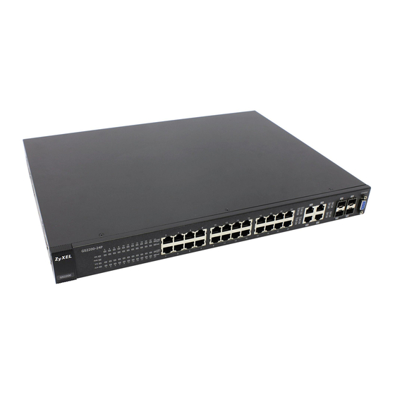
H A PT ER Hardware Panels 3.1 Overview This chapter describes the front panel and rear panel of the Switch and shows you how to make the hardware connections. 3.2 Front Panels The following figure shows the front panel of the Switch. Figure 9 Front Panel (GS2200-8) LEDs Console Port... - Page 32 Chapter 3 Hardware Panels Figure 11 Front Panel (GS2200-24) LEDs Console Port Dual Personality Interfaces Ethernet Ports Figure 12 Front Panel (GS2200-24P) LEDs Console Port Dual Personality Interfaces PoE Ethernet Ports The following table describes the port labels on the front panel. Table 2 Front Panel Connections LABEL DESCRIPTION...
-
Page 33: Console Port
Chapter 3 Hardware Panels Table 2 Front Panel Connections (continued) LABEL DESCRIPTION 2 or 4 Dual Each interface has one 100/1000 Mbps RJ-45 port and one Small Form-Factor Pluggable Personality (SFP) slot (also called a mini-GBIC slot), with one port or transceiver active at a time. Interfaces Note: The ports change to fiber mode directly when inserting the fiber module. -
Page 34: Mini-Gbic Slots
Chapter 3 Hardware Panels signal on the cable and using half duplex mode. When the Switch’s auto-negotiation is turned off, an Ethernet port uses the pre-configured speed and duplex mode when making a connection, thus requiring you to make sure that the settings of the peer Ethernet port are the same in order to connect. -
Page 35: Power Connector
Chapter 3 Hardware Panels Connect the fiber optic cables to the transceiver. Figure 13 Transceiver Installation Example Figure 14 Connecting the Fiber Optic Cables 3.2.3.2 Transceiver Removal Use the following steps to remove a mini-GBIC transceiver (SFP module). Remove the fiber optic cables from the transceiver. Open the transceiver’s latch (latch styles vary). -
Page 36: Leds
Chapter 3 Hardware Panels To connect power to the Switch, insert the female end of the power cord to the AC power receptacle on the front panel. Connect the other end of the supplied power cord to a power outlet. Make sure that no objects obstruct the airflow of the fans (located on the side of the unit). -
Page 37: Technical Reference
Technical Reference... -
Page 39: The Web Configurator
H A PT ER The Web Configurator 4.1 Overview This section introduces the configuration and functions of the web configurator. The web configurator is an HTML-based management interface that allows easy Switch setup and management via Internet browser. Use Internet Explorer 6.0 and later, Netscape Navigator 7.0 and later, Mozilla Firefox 3.0 and later versions. -
Page 40: The Status Screen
Chapter 4 The Web Configurator 4.3 The Status Screen The Status screen is the first screen that displays when you access the web configurator. This guide uses the GS2200-24P screens as an example. The screens may vary slightly for different models. The following figure shows the navigating components of a web configurator screen. - Page 41 Chapter 4 The Web Configurator E - Click this link to display web help pages. The help pages provide descriptions for all of the configuration screens. In the navigation panel, click a main link to reveal a list of submenu links. Table 4 Navigation Panel Sub-links Overview ADVANCED BASIC SETTING...
- Page 42 Chapter 4 The Web Configurator Table 5 Navigation Panel Links (continued) LINK DESCRIPTION VLAN This link takes you to screens where you can configure port-based or 802.1Q VLAN (depending on what you configured in the Switch Setup menu). You can also configure a protocol based VLAN or a subnet based VLAN in these screens.
- Page 43 Chapter 4 The Web Configurator Table 5 Navigation Panel Links (continued) LINK DESCRIPTION DiffServ This link takes you to screens where you can enable DiffServ, configure marking rules and set DSCP-to-IEEE802.1p mappings. DHCP This link takes you to screens where you can configure the DHCP settings. ARP Learning This link takes you to a screen where you can configure ARP learning mode on a per-port basis.
-
Page 44: Change Your Password
Chapter 4 The Web Configurator 4.3.1 Change Your Password After you log in for the first time, it is recommended you change the default administrator password. Click Management > Access Control > Logins to display the next screen. Figure 20 Change Administrator Login Password 4.4 Saving Your Configuration When you are done modifying the settings in a screen, click Apply to save your changes back to the run-time memory. -
Page 45: Resetting The Switch
Chapter 4 The Web Configurator Delete all port-based VLANs with the CPU port as a member. The “CPU port” is the management port of the Switch. Filter all traffic to the CPU port. Disable all ports. Misconfigure the text configuration file. Forget the password and/or IP address. -
Page 46: Logging Out Of The Web Configurator
Chapter 4 The Web Configurator 4.7 Logging Out of the Web Configurator Click Logout in a screen to exit the web configurator. You have to log in with your password again after you log out. This is recommended after you finish a management session for security reasons. Figure 21 Web Configurator: Logout Screen 4.8 Help The web configurator’s online help has descriptions of individual screens and some supplementary... -
Page 47: Initial Setup Example
H A PT ER Initial Setup Example 5.1 Overview This chapter shows how to set up the Switch for an example network. The following lists the configuration steps for the initial setup: • Create a VLAN • Set port VLAN ID •... -
Page 48: Setting Port Vid
Chapter 5 Initial Setup Example Click Advanced Application > VLAN in the navigation panel and click the Static VLAN link. In the Static VLAN screen, select ACTIVE, enter a descriptive name in the Name field and enter 2 in the VLAN Group ID field for the VLAN2 network. -
Page 49: Configuring Switch Management Ip Address
Chapter 5 Initial Setup Example In the example network, configure 2 as the port VID on port 1 so that any untagged frames received on that port get sent to VLAN 2. Figure 23 Initial Setup Network Example: Port VID Click Advanced Applications >... - Page 50 Chapter 5 Initial Setup Example Connect your computer to any Ethernet port on the Switch. Make sure your computer is in the same subnet as the Switch. Open your web browser and enter 192.168.1.1 (the default IP address) in the address bar to access the web configurator.
-
Page 51: Tutorials
H A PT ER Tutorials 6.1 Overview This chapter provides some examples of using the web configurator to set up and use the Switch. The tutorials include: • How to Use DHCP Snooping on the Switch • How to Use DHCP Relay on the Switch 6.2 How to Use DHCP Snooping on the Switch You only want DHCP server A connected to port 5 to assign IP addresses to all devices in VLAN network (V). - Page 52 Chapter 6 Tutorials Go to Advanced Application > VLAN > Static VLAN, and create a VLAN with ID of 100. Add ports 5, 6 and 7 in the VLAN by selecting Fixed in the Control field as shown. Deselect Tx Tagging because you don’t want outgoing traffic to contain this VLAN tag. Click Add.
- Page 53 Chapter 6 Tutorials Go to Advanced Application > IP Source Guard > DHCP snooping > Configure, activate and specify VLAN 100 as the DHCP VLAN as shown. Click Apply. Tutorial: Specify DHCP VLAN Figure 28 Click the Port link at the top right corner. The DHCP Snooping Port Configure screen appears.
-
Page 54: How To Use Dhcp Relay On The Switch
Chapter 6 Tutorials Go to Advanced Application > IP Source Guard > DHCP snooping > Configure > VLAN, show VLAN 100 by entering 100 in the Start VID and End VID fields and click Apply. Then select Yes in the Enabled field of the VLAN 100 entry shown at the bottom section of the screen. If you want to add more information in the DHCP request packets such as source VLAN ID or system name, you can also select the Option82 and Information fields in the entry. -
Page 55: Dhcp Relay Tutorial Introduction
Chapter 6 Tutorials 6.3.1 DHCP Relay Tutorial Introduction In this example, you have configured your DHCP server (192.168.2.3) and want to have it assign a specific IP address (say 172.16.1.18) to DHCP client A based on the system name, VLAN ID and port number in the DHCP request. - Page 56 Chapter 6 Tutorials Go to Basic Setting > Switch Setup and set the VLAN type to 802.1Q. Click Apply to save the settings to the run-time memory. Figure 33 Tutorial: Set VLAN Type to 802.1Q Click Advanced Application > VLAN > Static VLAN. In the Static VLAN screen, select ACTIVE, enter a descriptive name (VLAN 102 for example) in the Name field and enter 102 in the VLAN Group ID field.
- Page 57 Chapter 6 Tutorials Click Add to save the settings to the run-time memory. Settings in the run-time memory are lost when the Switch’s power is turned off. Figure 34 Tutorial: Create a Static VLAN Click the VLAN Status link in the Static VLAN screen and then the VLAN Port Setting link in the VLAN Status screen.
-
Page 58: Configuring Dhcp Relay
Chapter 6 Tutorials 10 Click Apply to save your changes back to the run-time memory. Figure 36 Tutorial: Add Tag for Frames Received on Port 2 11 Click the Save link in the upper right corner of the web configurator to save your configuration permanently. -
Page 59: Troubleshooting
Chapter 6 Tutorials Click Apply to save your changes back to the run-time memory. Figure 37 Tutorial: Set DHCP Server and Relay Information Click the Save link in the upper right corner of the web configurator to save your configuration permanently. -
Page 60: System Status And Port Statistics
H A PT ER System Status and Port Statistics 7.1 Overview This chapter describes the screens for system status (web configurator home page), port details and PoE status. The home screen of the web configurator displays a port statistical summary with links to each port showing statistical details. -
Page 61: Port Status Summary
Chapter 7 System Status and Port Statistics 7.2 Port Status Summary To view the port statistics, click Status in all web configurator screens to display the Status screen as shown next. Figure 38 Status (GS2200-24) Figure 39 Status (GS2200-24P) The following table describes the labels in this screen. Table 7 Status LABEL DESCRIPTION... - Page 62 Chapter 7 System Status and Port Statistics Table 7 Status (continued) LABEL DESCRIPTION Link This field displays the speed (either 100M for 100Mbps or 1000M for 1000Mbps) and the duplex (F for full duplex or H for half). It also shows the cable type (Copper or Fiber) for the combo ports.
-
Page 63: Status: Port Details
Chapter 7 System Status and Port Statistics 7.2.1 Status: Port Details Click a number in the Port column in the Status screen to display individual port statistics. Use this screen to check status and detailed performance data about an individual port on the Switch. Figure 40 Status >... - Page 64 Chapter 7 System Status and Port Statistics Table 8 Status: Port Details (continued) LABEL DESCRIPTION Status If STP (Spanning Tree Protocol) is enabled, this field displays the STP state of the port (see Section 13.1 on page 109 for more information). If STP is disabled, this field displays FORWARDING if the link is up, otherwise, it displays STOP.
- Page 65 Chapter 7 System Status and Port Statistics Table 8 Status: Port Details (continued) LABEL DESCRIPTION 128-255 This field shows the number of packets (including bad packets) received that were between 128 and 255 octets in length. 256-511 This field shows the number of packets (including bad packets) received that were between 256 and 511 octets in length.
-
Page 66: Basic Setting
H A PT ER Basic Setting 8.1 Overview This chapter describes how to configure the System Info, General Setup, Switch Setup, IP Setup, Port Setup, and PoE screens. 8.1.1 What You Can Do • Use the System Info screen (Section 8.2 on page 67) to check the firmware version number. -
Page 67: System Information
Chapter 8 Basic Setting 8.2 System Information In the navigation panel, click Basic Setting > System Info to display the screen as shown. You can check the firmware version number. Figure 41 Basic Setting > System Info The following table describes the labels in this screen. Table 9 Basic Setting >... - Page 68 Chapter 8 Basic Setting Table 9 Basic Setting > System Info (continued) LABEL DESCRIPTION Fan Speed A properly functioning fan is an essential component (along with a sufficiently ventilated, (RPM) cool operating environment) in order for the device to stay within the temperature threshold. Each fan has a sensor that is capable of detecting and reporting if the fan speed falls below the threshold shown.
-
Page 69: General Setup
Chapter 8 Basic Setting 8.3 General Setup Use this screen to configure general settings such as the system name and time. Click Basic Setting > General Setup in the navigation panel to display the screen as shown. Figure 42 Basic Setting > General Setup The following table describes the labels in this screen. -
Page 70: Introduction To Vlans
Chapter 8 Basic Setting Table 10 Basic Setting > General Setup (continued) LABEL DESCRIPTION New Time Enter the new time in hour, minute and second format. The new time then appears in the (hh:min:ss) Current Time field after you click Apply. Current Date This field displays the date you open this menu. -
Page 71: Switch Setup Screen
Chapter 8 Basic Setting VLAN also increases network performance by limiting broadcasts to a smaller and more manageable logical broadcast domain. In traditional switched environments, all broadcast packets go to each and every individual port. With VLAN, all broadcasts are confined to a specific broadcast domain. -
Page 72: Ip Setup
Chapter 8 Basic Setting Table 11 Basic Setting > Switch Setup (continued) LABEL DESCRIPTION Join Timer Join Timer sets the duration of the Join Period timer for GVRP in milliseconds. Each port has a Join Period timer. The allowed Join Time range is between 100 and 65535 milliseconds; the default is 200 milliseconds. -
Page 73: Management Ip Addresses
Chapter 8 Basic Setting 8.6.1 Management IP Addresses The Switch needs an IP address for it to be managed over the network. The factory default IP address is 192.168.1.1. The subnet mask specifies the network number portion of an IP address. The factory default subnet mask is 255.255.255.0. - Page 74 Chapter 8 Basic Setting Table 12 Basic Setting > IP Setup (continued) LABEL DESCRIPTION DHCP Client Select this option if you have a DHCP server that can assign the Switch an IP address, subnet mask, a default gateway IP address and a domain name server IP address automatically.
-
Page 75: Port Setup
Chapter 8 Basic Setting 8.7 Port Setup Use this screen to configure Switch port settings. Click Basic Setting > Port Setup in the navigation panel to display the configuration screen. Figure 45 Basic Setting > Port Setup The following table describes the labels in this screen. Table 13 Basic Setting >... -
Page 76: Poe Status
Chapter 8 Basic Setting Table 13 Basic Setting > Port Setup (continued) LABEL DESCRIPTION Speed/Duplex Select the speed and the duplex mode of the Ethernet connection on this port. Choices are Auto, 10M/Half Duplex, 10M/Full Duplex, 100M/Half Duplex, 100M/Full Duplex and 1000M/Full Duplex (Gigabit connections only). - Page 77 5 to 8 on the GS2200-8HP and ports 1 to 24 on the GS2200-24P can supply power of up to 15.4W per Ethernet port. Note: The GS2200-24P is compatible with ZyXEL’s PPS250 power module. The PPS250 provides additional external PoE power budget on top of the internal power budget of the GS2200-24P.
- Page 78 Chapter 8 Basic Setting To view the current amount of power that PDs are receiving from the Switch, click Basic Setting > PoE. Figure 47 Basic Setting > PoE Status The following table describes the labels in this screen. Table 14 Basic Setting > PoE Status LABEL DESCRIPTION PoE Status...
-
Page 79: Poe Setup
Chapter 8 Basic Setting Table 14 Basic Setting > PoE Status (continued) LABEL DESCRIPTION Class This shows the IEEE 802.3af power classification of the PD. This is a number from 0 to 4, where each value represents a range of power (W) and power current (mA) that the PD requires to function. - Page 80 Chapter 8 Basic Setting Click the PoE Setup link in the Basic Setting > PoE Status screen. The following screen opens. Figure 48 Basic Setting > PoE > PoE Setup The following table describes the labels in this screen. Table 15 Basic Setting > PoE > PoE Setup LABEL DESCRIPTION PoE Mode...
- Page 81 Chapter 8 Basic Setting Table 15 Basic Setting > PoE > PoE Setup (continued) LABEL DESCRIPTION Apply Click Apply to save your changes to the Switch’s run-time memory. The Switch loses these changes if it is turned off or loses power, so use the Save link on the top navigation panel to save your changes to the non-volatile memory when you are done configuring.
- Page 82 Chapter 8 Basic Setting GS2200-8/24 User’s Guide...
-
Page 83: Vlan
H A PT ER VLAN 9.1 Overview This chapter shows you how to configure 802.1Q tagged and port-based VLANs. The type of screen you see here depends on the VLAN Type you selected in the Switch Setup screen. 9.1.1 What You Can Do •... - Page 84 Chapter 9 VLAN level is significant and the default VID of the ingress port is given as the VID of the frame. Of the 4096 possible VIDs, a VID of 0 is used to identify priority frames and value 4095 (FFF) is reserved, so the maximum possible VLAN configurations are 4,094.
-
Page 85: Port Vlan Trunking
Chapter 9 VLAN Table 16 IEEE 802.1Q VLAN Terminology (continued) VLAN PARAMETER TERM DESCRIPTION VLAN Administrative Registration Fixed Fixed registration ports are permanent VLAN members. Control Registration Ports with registration forbidden are forbidden to join the Forbidden specified VLAN. Normal Registration Ports dynamically join a VLAN using GVRP. -
Page 86: Static Vlan
Chapter 9 VLAN Static VLAN Use a static VLAN to decide whether an incoming frame on a port should be • sent to a VLAN group as normal depending on its VLAN tag. • sent to a group whether it has a VLAN tag or not. •... -
Page 87: Vlan Details
Chapter 9 VLAN Table 17 Advanced Application > VLAN: VLAN Status (continued) LABEL DESCRIPTION Status This field shows how this VLAN was added to the Switch. dynamic: using GVRP static: added as a permanent entry Change Pages Click Previous or Next to show the previous/next screen if all status information cannot be seen in one screen. -
Page 88: Configure A Static Vlan
Chapter 9 VLAN 9.3 Configure a Static VLAN Use this screen to configure and view 802.1Q VLAN parameters for the Switch. To configure a static VLAN, click Static VLAN in the VLAN Status screen to display the screen as shown next. Figure 53 Advanced Application >... - Page 89 Chapter 9 VLAN Table 19 Advanced Application > VLAN > Static VLAN (continued) LABEL DESCRIPTION Settings in this row apply to all ports. Use this row only if you want to make some settings the same for all ports. Use this row first to set the common settings and then make adjustments on a port-by-port basis.
-
Page 90: Configure Vlan Port Settings
Chapter 9 VLAN 9.4 Configure VLAN Port Settings Use the VLAN Port Setting screen to configure the static VLAN (IEEE 802.1Q) settings on a port. Click the VLAN Port Setting link in the VLAN Status screen. Figure 54 Advanced Application > VLAN > VLAN Port Setting The following table describes the labels in this screen. -
Page 91: Subnet Based Vlans
Chapter 9 VLAN Table 20 Advanced Application > VLAN > VLAN Port Setting (continued) LABEL DESCRIPTION PVID A PVID (Port VLAN ID) is a tag that adds to incoming untagged frames received on a port so that the frames are forwarded to the VLAN group that the tag defines. Enter a number between 1and 4094 as the port VLAN ID. -
Page 92: Configuring Subnet Based Vlan
Chapter 9 VLAN untagged incoming frames will be classified based on their source IP subnet and prioritized accordingly. That is video services receive the highest priority and data the lowest. Figure 55 Subnet Based VLAN Application Example Tagged Frames Internet Untagged Frames 10.1.1.0/24... - Page 93 Chapter 9 VLAN Figure 56 Advanced Application > VLAN > VLAN Port Setting > Subnet Based VLAN The following table describes the labels in this screen. Table 21 Advanced Application > VLAN > VLAN Port Setting > Subnet Based VLAN Setup LABEL DESCRIPTION Active...
-
Page 94: Protocol Based Vlans
Chapter 9 VLAN Table 21 Advanced Application > VLAN > VLAN Port Setting > Subnet Based VLAN Setup LABEL DESCRIPTION Index This is the index number identifying this subnet based VLAN. Click on any of these numbers to edit an existing subnet based VLAN. Active This field shows whether the subnet based VLAN is active or not. - Page 95 Chapter 9 VLAN Note: Protocol-based VLAN applies to un-tagged packets and is applicable only when you use IEEE 802.1Q tagged VLAN. Note: You can not enable protocol-based VLANs on the Switch when the Guest VLAN feature is activated on a port. Figure 58 Advanced Application >...
-
Page 96: Port-Based Vlan Setup
Chapter 9 VLAN Table 22 Advanced Application > VLAN > VLAN Port Setting > Protocol Based VLAN Setup LABEL DESCRIPTION Name This field shows the name the protocol based VLAN. Ethernet Type This field shows which Ethernet protocol is part of this protocol based VLAN. This field shows the VLAN ID of the port. -
Page 97: Configure A Port-Based Vlan
Chapter 9 VLAN 9.7.1 Configure a Port-based VLAN Select Port Based as the VLAN Type in the Basic Setting > Switch Setup screen and then click Advanced Application > VLAN from the navigation panel to display the next screen. Figure 59 Port Based VLAN Setup (All Connected) GS2200-8/24 User’s Guide... - Page 98 Chapter 9 VLAN Figure 60 Port Based VLAN Setup (Port Isolation) GS2200-8/24 User’s Guide...
-
Page 99: Technical Reference
Chapter 9 VLAN The following table describes the labels in this screen. Table 23 Port Based VLAN Setup label Description Setting Wizard Choose All connected or Port isolation. All connected means all ports can communicate with each other, that is, there are no virtual LANs. - Page 100 Chapter 9 VLAN Leave the priority set to 0 and click Add. Figure 61 Protocol Based VLAN Configuration Example To add more ports to this protocol based VLAN. Click the index number of the protocol based VLAN entry. Click 1 Change the value in the Port field to the next port you want to add.
-
Page 101: Static Mac Forward Setup
HAPTER Static MAC Forward Setup 10.1 Overview This chapter discusses how to configure forwarding rules based on MAC addresses of devices on your network. Use these screens to configure static MAC address forwarding. 10.1.1 What You Can Do Use the Static MAC Forwarding screen (Section 10.2 on page 101) to assign static MAC addresses for a port. - Page 102 Chapter 10 Static MAC Forward Setup The following table describes the labels in this screen. Table 24 Advanced Application > Static MAC Forwarding LABEL DESCRIPTION Active Select this check box to activate your rule. You may temporarily deactivate a rule without deleting it by clearing this check box.
-
Page 103: Static Multicast Forward Setup
HAPTER Static Multicast Forward Setup 11.1 Overview This chapter discusses how to configure forwarding rules based on multicast MAC addresses of devices on your network. Use these screens to configure static multicast address forwarding. 11.1.1 What You Can Do Use the Static Multicast Forward Setup screen (Section 11.2 on page 104) to configure rules to forward specific multicast frames, such as streaming or control frames, to specific port(s). -
Page 104: Configuring Static Multicast Forwarding
Chapter 11 Static Multicast Forward Setup within a VLAN group. Figure 64 shows frames being forwarded to devices connected to port 3. Figure 65 shows frames being forwarded to ports 2 and 3 within VLAN group 4. Figure 63 No Static Multicast Forwarding Figure 64 Static Multicast Forwarding to A Single Port Figure 65 Static Multicast Forwarding to Multiple Ports 11.2 Configuring Static Multicast Forwarding... - Page 105 Chapter 11 Static Multicast Forward Setup Click Advanced Application > Static Multicast Forwarding to display the configuration screen as shown. Figure 66 Advanced Application > Static Multicast Forwarding The following table describes the labels in this screen. Table 25 Advanced Application > Static Multicast Forwarding LABEL DESCRIPTION Active...
- Page 106 Chapter 11 Static Multicast Forward Setup Table 25 Advanced Application > Static Multicast Forwarding (continued) LABEL DESCRIPTION Port This field displays the port(s) within a identified VLAN group to which frames containing the specified multicast MAC address will be forwarded. Delete Click Delete to remove the selected entry from the summary table.
-
Page 107: Filtering
HAPTER Filtering 12.1 Overview This chapter discusses MAC address port filtering. Filtering means sifting traffic going through the Switch based on the source and/or destination MAC addresses and VLAN group (ID). 12.1.1 What You Can Do Use the Filtering screen (Section 12.2 on page 107) to create rules for traffic going through the Switch. - Page 108 Chapter 12 Filtering The following table describes the related labels in this screen. Table 26 Advanced Application > Filtering LABEL DESCRIPTION Active Make sure to select this check box to activate your rule. You may temporarily deactivate a rule without deleting it by deselecting this check box. Name Type a descriptive name (up to 32 printable ASCII characters) for this rule.
-
Page 109: Spanning Tree Protocol
HAPTER Spanning Tree Protocol 13.1 Overview The Switch supports Spanning Tree Protocol (STP), Rapid Spanning Tree Protocol (RSTP) and Multiple Spanning Tree Protocol (MSTP) as defined in the following standards. • IEEE 802.1D Spanning Tree Protocol • IEEE 802.1w Rapid Spanning Tree Protocol •... - Page 110 Chapter 13 Spanning Tree Protocol (Rapid) Spanning Tree Protocol (R)STP detects and breaks network loops and provides backup links between switches, bridges or routers. It allows a switch to interact with other (R)STP -compliant switches in your network to ensure that only one path exists between any two stations on the network. The Switch uses IEEE 802.1w RSTP (Rapid Spanning Tree Protocol) that allows faster convergence of the spanning tree than STP (while also being backwards compatible with STP-only aware bridges).
-
Page 111: Stp Port States
All BPDUs are received and processed. All information frames are received and forwarded. Multiple RSTP MRSTP (Multiple RSTP) is ZyXEL’s proprietary feature that is compatible with RSTP and STP. With MRSTP, you can have more than one spanning tree on your Switch and assign port(s) to each tree. -
Page 112: Spanning Tree Protocol Status Screen
Chapter 13 Spanning Tree Protocol Multiple STP Multiple Spanning Tree Protocol (IEEE 802.1s) is backward compatible with STP/RSTP and addresses the limitations of existing spanning tree protocols (STP and RSTP) in networks to include the following features: • One Common and Internal Spanning Tree (CIST) that represents the entire network’s connectivity. -
Page 113: Spanning Tree Configuration
Chapter 13 Spanning Tree Protocol 13.3 Spanning Tree Configuration Use the Spanning Tree Configuration screen to activate one of the STP modes on the Switch. Click Configuration in the Advanced Application > Spanning Tree Protocol. Figure 70 Advanced Application > Spanning Tree Protocol > Configuration The following table describes the labels in this screen. -
Page 114: Configure Rapid Spanning Tree Protocol
Chapter 13 Spanning Tree Protocol 13.4 Configure Rapid Spanning Tree Protocol Use this screen to configure RSTP settings, see (Rapid) Spanning Tree Protocol on page 110 more information on RSTP. Click RSTP in the Advanced Application > Spanning Tree Protocol screen. -
Page 115: Rapid Spanning Tree Protocol Status
Chapter 13 Spanning Tree Protocol Table 30 Advanced Application > Spanning Tree Protocol > RSTP (continued) LABEL DESCRIPTION Hello Time This is the time interval in seconds between BPDU (Bridge Protocol Data Units) configuration message generations by the root switch. The allowed range is 1 to 10 seconds. - Page 116 Chapter 13 Spanning Tree Protocol Note: This screen is only available after you activate RSTP on the Switch. Figure 72 Advanced Application > Spanning Tree Protocol > Status: RSTP The following table describes the labels in this screen. Table 31 Advanced Application > Spanning Tree Protocol > Status: RSTP LABEL DESCRIPTION Configuration...
-
Page 117: Configure Multiple Rapid Spanning Tree Protocol
Chapter 13 Spanning Tree Protocol 13.6 Configure Multiple Rapid Spanning Tree Protocol To configure MRSTP, click MRSTP in the Advanced Application > Spanning Tree Protocol screen. See Multiple RSTP on page 111 for more information on MRSTP. Figure 73 Advanced Application > Spanning Tree Protocol > MRSTP The following table describes the labels in this screen. -
Page 118: Multiple Rapid Spanning Tree Protocol Status
Chapter 13 Spanning Tree Protocol Table 32 Advanced Application > Spanning Tree Protocol > MRSTP (continued) LABEL DESCRIPTION Hello Time This is the time interval in seconds between BPDU (Bridge Protocol Data Units) configuration message generations by the root switch. The allowed range is 1 to 10 seconds. - Page 119 Chapter 13 Spanning Tree Protocol Note: This screen is only available after you activate MRSTP on the Switch. Figure 74 Advanced Application > Spanning Tree Protocol > Status: MRSTP The following table describes the labels in this screen. Table 33 Advanced Application > Spanning Tree Protocol > Status: MRSTP LABEL DESCRIPTION Configuration...
-
Page 120: Configure Multiple Spanning Tree Protocol
Chapter 13 Spanning Tree Protocol 13.8 Configure Multiple Spanning Tree Protocol To configure MSTP, click MSTP in the Advanced Application > Spanning Tree Protocol screen. Multiple STP on page 112 for more information on MSTP. Figure 75 Advanced Application > Spanning Tree Protocol > MSTP GS2200-8/24 User’s Guide... - Page 121 Chapter 13 Spanning Tree Protocol The following table describes the labels in this screen. Table 34 Advanced Application > Spanning Tree Protocol > MSTP LABEL DESCRIPTION Status Click Status to display the MSTP Status screen (see Figure 77 on page 124).
- Page 122 Chapter 13 Spanning Tree Protocol Table 34 Advanced Application > Spanning Tree Protocol > MSTP (continued) LABEL DESCRIPTION VLAN Range Enter the start of the VLAN ID range that you want to add or remove from the VLAN range edit area in the Start field. Enter the end of the VLAN ID range that you want to add or remove from the VLAN range edit area in the End field.
-
Page 123: Multiple Spanning Tree Protocol Port Configuration
Chapter 13 Spanning Tree Protocol 13.8.1 Multiple Spanning Tree Protocol Port Configuration To configure MSTP ports, click Port in the Advanced Application > Spanning Tree Protocol > MSTP screen. Figure 76 Advanced Application > Spanning Tree Protocol > MSTP > Port The following table describes the labels in this screen. - Page 124 Chapter 13 Spanning Tree Protocol Note: This screen is only available after you activate MSTP on the Switch. Figure 77 Advanced Application > Spanning Tree Protocol > Status: MSTP The following table describes the labels in this screen. Table 36 Advanced Application > Spanning Tree Protocol > Status: MSTP LABEL DESCRIPTION Configuration...
-
Page 125: Technical Reference
Chapter 13 Spanning Tree Protocol Table 36 Advanced Application > Spanning Tree Protocol > Status: MSTP (continued) LABEL DESCRIPTION Port ID This is the priority and number of the port on the Switch through which this Switch must communicate with the root of the Spanning Tree. Configuration This field displays the configuration name for this MST region. -
Page 126: Mstp Network Example
Chapter 13 Spanning Tree Protocol 13.10.1 MSTP Network Example The following figure shows a network example where two VLANs are configured on the two switches. If the switches are using STP or RSTP, the link for VLAN 2 will be blocked as STP and RSTP allow only one link in the network and block the redundant link. -
Page 127: Mst Instance
Chapter 13 Spanning Tree Protocol Devices that belong to the same MST region are configured to have the same MSTP configuration identification settings. These include the following parameters: • Name of the MST region • Revision level as the unique number for the MST region •... - Page 128 Chapter 13 Spanning Tree Protocol that runs between MST regions and single spanning tree devices. A network may contain multiple MST regions and other network segments running RSTP. Figure 81 MSTP and Legacy RSTP Network Example GS2200-8/24 User’s Guide...
-
Page 129: Bandwidth Control
HAPTER Bandwidth Control 14.1 Overview This chapter shows you how you can cap the maximum bandwidth using the Bandwidth Control screen. Bandwidth control means defining a maximum allowable bandwidth for out-going traffic flows on a port. 14.1.1 What You Can Do Use the Bandwidth Control screen (Section 14.2 on page 130) to limit the bandwidth for traffic... -
Page 130: Bandwidth Control Setup
Chapter 14 Bandwidth Control 14.2 Bandwidth Control Setup Click Advanced Application > Bandwidth Control in the navigation panel to bring up the screen as shown next. Figure 82 Advanced Application > Bandwidth Control The following table describes the related labels in this screen. Table 37 Advanced Application >... - Page 131 Chapter 14 Bandwidth Control Table 37 Advanced Application > Bandwidth Control (continued) LABEL DESCRIPTION Apply Click Apply to save your changes to the Switch’s run-time memory. The Switch loses these changes if it is turned off or loses power, so use the Save link on the top navigation panel to save your changes to the non-volatile memory when you are done configuring.
-
Page 132: Broadcast Storm Control
HAPTER Broadcast Storm Control 15.1 Overview This chapter introduces and shows you how to configure the broadcast storm control feature. Broadcast storm control limits the number of broadcast, multicast and destination lookup failure (DLF) packets the Switch receives per second on the ports. When the maximum number of allowable broadcast, multicast and/or DLF packets is reached per second, the subsequent packets are discarded. -
Page 133: Broadcast Storm Control Setup
Chapter 15 Broadcast Storm Control 15.2 Broadcast Storm Control Setup Click Advanced Application > Broadcast Storm Control in the navigation panel to display the screen as shown next. Figure 83 Advanced Application > Broadcast Storm Control The following table describes the labels in this screen. Table 38 Advanced Application >... -
Page 134: Mirroring
HAPTER Mirroring 16.1 Overview This chapter discusses port mirroring setup screens. Port mirroring allows you to copy a traffic flow to a monitor port (the port you copy the traffic to) in order that you can examine the traffic from the monitor port without interference. 16.1.1 What You Can Do Use the Mirroring screen (Section 16.2 on page... -
Page 135: Port Mirroring Setup
Chapter 16 Mirroring 16.2 Port Mirroring Setup Click Advanced Application > Mirroring in the navigation panel to display the Mirroring screen. Use this screen to select a monitor port and specify the traffic flow to be copied to the monitor port. Figure 84 Advanced Application >... - Page 136 Chapter 16 Mirroring Table 39 Advanced Application > Mirroring (continued) LABEL DESCRIPTION Apply Click Apply to save your changes to the Switch’s run-time memory. The Switch loses these changes if it is turned off or loses power, so use the Save link on the top navigation panel to save your changes to the non-volatile memory when you are done configuring.
-
Page 137: Link Aggregation
HAPTER Link Aggregation 17.1 Overview This chapter shows you how to logically aggregate physical links to form one logical, higher- bandwidth link. Link aggregation (trunking) is the grouping of physical ports into one logical higher-capacity link. You may want to trunk ports if for example, it is cheaper to use multiple lower-speed links than to under-utilize a high-speed, but more costly, single-port link. -
Page 138: Link Aggregation Status
Chapter 17 Link Aggregation is, if an operational port fails, then one of the “standby” ports become operational without user intervention. Please note that: • You must connect all ports point-to-point to the same Ethernet switch and configure the ports for LACP trunking. - Page 139 Chapter 17 Link Aggregation The following table describes the labels in this screen. Table 42 Advanced Application > Link Aggregation Status LABEL DESCRIPTION Group ID This field displays the group ID to identify a trunk group, that is, one logical link containing multiple ports.
-
Page 140: Link Aggregation Setting
Chapter 17 Link Aggregation 17.3 Link Aggregation Setting Click Advanced Application > Link Aggregation > Link Aggregation Setting to display the screen shown next. See Section 17.1 on page 137 for more information on link aggregation. Figure 86 Advanced Application > Link Aggregation > Link Aggregation Setting The following table describes the labels in this screen. - Page 141 Chapter 17 Link Aggregation Table 43 Advanced Application > Link Aggregation > Link Aggregation Setting (continued) LABEL DESCRIPTION Criteria Select the outgoing traffic distribution type. Packets from the same source and/or to the same destination are sent over the same link within the trunk. By default, the Switch uses the src-dst-mac distribution type.
-
Page 142: Link Aggregation Control Protocol
Chapter 17 Link Aggregation 17.4 Link Aggregation Control Protocol Click Advanced Application > Link Aggregation > Link Aggregation Setting > LACP to display the screen shown next. See Dynamic Link Aggregation on page 137 for more information on dynamic link aggregation. Figure 87 Advanced Application >... -
Page 143: Technical Reference
Chapter 17 Link Aggregation Table 44 Advanced Application > Link Aggregation > Link Aggregation Setting > LACP (continued) LABEL DESCRIPTION System Priority LACP system priority is a number between 1 and 65,535. The switch with the lowest system priority (and lowest port number if system priority is the same) becomes the LACP “server”. The LACP “server”... - Page 144 Chapter 17 Link Aggregation Make your physical connections - make sure that the ports that you want to belong to the trunk group are connected to the same destination. The following figure shows ports 2-5 on switch A connected to switch B. Figure 88 Trunking Example - Physical Connections Configure static trunking - Click Advanced Application >...
-
Page 145: Port Authentication
HAPTER Port Authentication 18.1 Overview This chapter describes the IEEE 802.1x authentication method. Port authentication is a way to validate access to ports on the Switch to clients based on an external server (authentication server). The Switch supports the following method for port authentication: •... -
Page 146: Port Authentication Configuration
Chapter 18 Port Authentication authentication request to a RADIUS server. The RADIUS server validates whether this client is allowed access to the port. Figure 90 IEEE 802.1x Authentication Process New Connection Identity Request Login Credentials Authentication Request Access Challenge Challenge Request Challenge Response Access Request Authentication Reply... -
Page 147: Activate Ieee 802.1X Security
Chapter 18 Port Authentication 18.3 Activate IEEE 802.1x Security Use this screen to activate IEEE 802.1x security. In the Port Authentication screen click 802.1x to display the configuration screen as shown. Figure 92 Advanced Application > Port Authentication > 802.1x The following table describes the labels in this screen. -
Page 148: Guest Vlan
Chapter 18 Port Authentication Table 45 Advanced Application > Port Authentication > 802.1x (continued) LABEL DESCRIPTION Reauth Specify if a subscriber has to periodically re-enter his or her username and password to stay connected to the port. Reauth-period Specify the length of time required to pass before a client has to re-enter his or her username and password to stay connected to the port. - Page 149 Chapter 18 Port Authentication Figure 94 Advanced Application > Port Authentication > 802.1x > Guest VLAN The following table describes the labels in this screen. Table 46 Advanced Application > Port Authentication > 802.1x > Guest VLAN LABEL DESCRIPTION Port This field displays a port number.
- Page 150 Chapter 18 Port Authentication Table 46 Advanced Application > Port Authentication > 802.1x > Guest VLAN (continued) LABEL DESCRIPTION Multi-Secure If you set Host-mode to Multi-Secure, specify the maximum number of users (between 1 and 9) that the Switch will authenticate on this port. Apply Click Apply to save your changes to the Switch’s run-time memory.
-
Page 151: Port Security
HAPTER Port Security 19.1 Overview This chapter shows you how to set up port security. Port security allows only packets with dynamically learned MAC addresses and/or configured static MAC addresses to pass through a port on the Switch. The Switch can learn up to 16K MAC addresses in total with no limit on individual ports other than the sum cannot exceed 16K. -
Page 152: Port Security Setup
Chapter 19 Port Security 19.2 Port Security Setup Click Advanced Application > Port Security in the navigation panel to display the screen as shown. Figure 95 Advanced Application > Port Security The following table describes the labels in this screen. Table 47 Advanced Application >... - Page 153 Chapter 19 Port Security Table 47 Advanced Application > Port Security (continued) LABEL DESCRIPTION Active Select this check box to enable the port security feature on this port. The Switch forwards packets whose MAC address(es) is in the MAC address table on this port. Packets with no matching MAC address(es) are dropped.
-
Page 154: Classifier
HAPTER Classifier 20.1 Overview This chapter introduces and shows you how to configure the packet classifier on the Switch. It also discusses Quality of Service (QoS) and classifier concepts as employed by the Switch. 20.1.1 What You Can Do Use the Classifier screen (Section 20.2 on page 154) to define the classifiers and view a summary of the classifier configuration. - Page 155 Chapter 20 Classifier Click Advanced Application > Classifier in the navigation panel to display the configuration screen as shown. Figure 96 Advanced Application > Classifier The following table describes the labels in this screen. Table 48 Advanced Application > Classifier LABEL DESCRIPTION Active...
-
Page 156: Viewing And Editing Classifier Configuration
Chapter 20 Classifier Table 48 Advanced Application > Classifier (continued) LABEL DESCRIPTION Destination Select Any to apply the rule to all MAC addresses. Address To specify a destination, select the second choice and type a MAC address in valid MAC address format (six hexadecimal character pairs). - Page 157 Chapter 20 Classifier Note: When two rules conflict with each other, a higher layer rule has priority over lower layer rule. Figure 97 Advanced Application > Classifier: Summary Table The following table describes the labels in this screen. Table 49 Classifier: Summary Table LABEL DESCRIPTION Index...
-
Page 158: Classifier Example
Chapter 20 Classifier Table 51 Common IP Protocol Types and Protocol Numbers PROTOCOL TYPE PROTOCOL NUMBER L2TP Some of the most common TCP and UDP port numbers are: Table 52 Common TCP and UDP Port Numbers PROTOCOL NAME TCP/UDP PORT NUMBER Telnet SMTP HTTP... - Page 159 Chapter 20 Classifier After you have configured a classifier, you can configure a policy (in the Policy screen) to define action(s) on the classified traffic flow. Figure 98 Classifier: Example GS2200-8/24 User’s Guide...
-
Page 160: Policy Rule
HAPTER Policy Rule 21.1 Policy Rules Overview This chapter shows you how to configure policy rules. A classifier distinguishes traffic into flows based on the configured criteria (refer to Chapter 20 on page 154 for more information). A policy rule ensures that a traffic flow gets the requested treatment in the network. - Page 161 Chapter 21 Policy Rule Click Advanced Applications > Policy Rule in the navigation panel to display the screen as shown. Figure 99 Advanced Application > Policy Rule The following table describes the labels in this screen. Table 53 Advanced Application > Policy Rule LABEL DESCRIPTION Active...
- Page 162 Chapter 21 Policy Rule Table 53 Advanced Application > Policy Rule (continued) LABEL DESCRIPTION Rate Limit You can configure the desired bandwidth available to a traffic flow. Traffic that exceeds the maximum bandwidth allocated (in cases where the network is congested) is dropped. Bandwidth Specify the bandwidth in kilobit per second (Kbps).
-
Page 163: Viewing And Editing Policy Configuration
Chapter 21 Policy Rule Table 53 Advanced Application > Policy Rule (continued) LABEL DESCRIPTION Delete Click Cancel to clear the Delete check boxes. Cancel This field displays the policy index number. Click an index number to edit the policy. 21.2.1 Viewing and Editing Policy Configuration To view a summary of the classifier configuration, scroll down to the summary table at the bottom of the Policy screen. -
Page 164: Policy Example
Chapter 21 Policy Rule 21.3 Policy Example The figure below shows an example Policy screen where you configure a policy to limit bandwidth on a traffic flow classified using the Example classifier (refer to Section 20.3 on page 158). Figure 101 Policy Example GS2200-8/24 User’s Guide... -
Page 165: Queuing Method
HAPTER Queuing Method 22.1 Overview This chapter introduces the queuing methods supported. Queuing is used to help solve performance degradation when there is network congestion. Use the Queuing Method screen to configure queuing algorithms for outgoing traffic. See also Priority Queue Assignment in Switch Setup and 802.1p Priority in Port Setup for related information. -
Page 166: Configuring Queuing
Chapter 22 Queuing Method an equal amount of bandwidth, and then moves to the end of the list; and so on, depending on the number of queues being used. This works in a looping fashion until a queue is empty. Weighted Round Robin Scheduling (WRR) uses the same algorithm as round robin scheduling, but services queues based on their priority and queue weight (the number you configure in the queue Weight field) rather than a fixed amount of bandwidth. - Page 167 Chapter 22 Queuing Method The following table describes the labels in this screen. Table 54 Advanced Application > Queuing Method LABEL DESCRIPTION Port This label shows the port you are configuring. Settings in this row apply to all ports. Use this row only if you want to make some settings the same for all ports. Use this row first to set the common settings and then make adjustments on a port-by-port basis.
-
Page 168: Multicast
HAPTER Multicast 23.1 Overview This chapter shows you how to configure various multicast features. Traditionally, IP packets are transmitted in one of either two ways - Unicast (1 sender to 1 recipient) or Broadcast (1 sender to everybody on the network). Multicast delivers IP packets to just a group of hosts on the network. - Page 169 Chapter 23 Multicast through it, picks out the group registration information, and configures multicasting accordingly. IGMP snooping allows the Switch to learn multicast groups without you having to manually configure them. The Switch forwards multicast traffic destined for multicast groups (that it has learned from IGMP snooping or that you have manually configured) to ports that are members of that group.
-
Page 170: Multicast Status
Chapter 23 Multicast MVR Modes You can set your Switch to operate in either dynamic or compatible mode. In dynamic mode, the Switch sends IGMP leave and join reports to the other multicast devices (such as multicast routers or servers) in the multicast VLAN. This allows the multicast devices to update the multicast forwarding table to forward or not forward multicast traffic to the receiver ports. -
Page 171: Multicast Setting
Chapter 23 Multicast The following table describes the labels in this screen. Table 55 Advanced Application > Multicast Status LABEL DESCRIPTION Index This is the index number of the entry. This field displays the multicast VLAN ID. Port This field displays the port number that belongs to the multicast group. Multicast Group This field displays IP multicast group addresses. - Page 172 Chapter 23 Multicast The following table describes the labels in this screen. Table 56 Advanced Application > Multicast > Multicast Setting LABEL DESCRIPTION IGMP Snooping Use these settings to configure IGMP Snooping. Active Select Active to enable IGMP Snooping to forward group multicast traffic only to ports that are members of that group.
- Page 173 Chapter 23 Multicast Table 56 Advanced Application > Multicast > Multicast Setting (continued) LABEL DESCRIPTION Max Group Num. Enter the number (0-255) of multicast groups this port is allowed to join. Once a port is registered in the specified number of multicast groups, any new IGMP join report frame(s) is dropped on this port.
-
Page 174: Igmp Snooping Vlan
Chapter 23 Multicast 23.4 IGMP Snooping VLAN Click Advanced Applications > Multicast in the navigation panel. Click the Multicast Setting link and then the IGMP Snooping VLAN link to display the screen as shown. See IGMP Snooping and VLANs on page 169 for more information on IGMP Snooping VLAN. -
Page 175: Igmp Filtering Profile
Chapter 23 Multicast Table 57 Advanced Application > Multicast > Multicast Setting > IGMP Snooping VLAN (continued) LABEL DESCRIPTION Cancel Click Cancel to reset the fields to your previous configuration. Clear Click this to clear the fields. Index This is the number of the IGMP snooping VLAN entry in the table. Name This field displays the descriptive name for this VLAN group. -
Page 176: The Mvr Screen
Chapter 23 Multicast Table 58 Advanced Application > Multicast > Multicast Setting > IGMP Filtering Profile (continued) LABEL DESCRIPTION End Address Type the ending multicast IP address for a range of IP addresses that you want to belong to the IGMP filter profile. If you want to add a single multicast IP address, enter it in both the Start Address and End Address fields. - Page 177 Chapter 23 Multicast Note: Your Switch automatically creates a static VLAN (with the same VID) when you create a multicast VLAN in this screen. Figure 109 Advanced Application > Multicast > Multicast Setting > MVR The following table describes the related labels in this screen. Table 59 Advanced Application >...
-
Page 178: Mvr Group Configuration
Chapter 23 Multicast Table 59 Advanced Application > Multicast > Multicast Setting > MVR (continued) LABEL DESCRIPTION Source Port Select this option to set this port as the MVR source port that sends and receives multicast traffic. All source ports must belong to a single multicast VLAN. Receiver Port Select this option to set this port as a receiver port that only receives multicast traffic. -
Page 179: Mvr Configuration Example
Chapter 23 Multicast The following table describes the labels in this screen. Table 60 Advanced Application > Multicast > Multicast Setting > MVR: Group Configuration LABEL DESCRIPTION Multicast Select a multicast VLAN ID (that you configured in the MVR screen) from the drop-down list VLAN ID box. - Page 180 Chapter 23 Multicast To configure the MVR settings on the Switch, create a multicast group in the MVR screen and set the receiver and source ports. Figure 112 MVR Configuration Example GS2200-8/24 User’s Guide...
- Page 181 Chapter 23 Multicast To set the Switch to forward the multicast group traffic to the subscribers, configure multicast group settings in the Group Configuration screen. The following figure shows an example where two multicast groups (News and Movie) are configured for the multicast VLAN 200. Figure 113 MVR Group Configuration Example Figure 114 MVR Group Configuration Example GS2200-8/24 User’s Guide...
-
Page 182: Aaa
HAPTER 24.1 Overview This chapter describes how to configure authentication and authorization settings on the Switch. The external servers that perform authentication and authorization functions are known as AAA servers. The Switch supports RADIUS (Remote Authentication Dial-In User Service, see Section on page 183) and TACACS+ (Terminal Access Controller Access-Control System Plus, see... -
Page 183: Aaa Screens
Chapter 24 AAA Local User Accounts By storing user profiles locally on the Switch, your Switch is able to authenticate and authorize users without interacting with a network AAA server. However, there is a limit on the number of users you may authenticate in this way (See Chapter 34 on page 255). - Page 184 Chapter 24 AAA the authentication features on the Switch. Click on the RADIUS Server Setup link in the AAA screen to view the screen as shown. Figure 117 Advanced Application > AAA > RADIUS Server Setup The following table describes the labels in this screen. Table 62 Advanced Application >...
- Page 185 Chapter 24 AAA Table 62 Advanced Application > AAA > RADIUS Server Setup (continued) LABEL DESCRIPTION Shared Secret Specify a password (up to 32 alphanumeric characters) as the key to be shared between the external RADIUS server and the Switch. This key is not sent over the network. This key must be the same on the external RADIUS server and the Switch.
-
Page 186: Tacacs+ Server Setup
Chapter 24 AAA 24.4 TACACS+ Server Setup Use this screen to configure your TACACS+ server settings. See Section on page 183 for more information on TACACS+ servers. Click on the TACACS+ Server Setup link in the AAA screen to view the screen as shown. Figure 118 Advanced Application >... - Page 187 Chapter 24 AAA Table 63 Advanced Application > AAA > TACACS+ Server Setup (continued) LABEL DESCRIPTION TCP Port The default port of a TACACS+ server for authentication is 49. You need not change this value unless your network administrator instructs you to do so. Shared Secret Specify a password (up to 32 alphanumeric characters) as the key to be shared between the external TACACS+ server and the Switch.
-
Page 188: Aaa Setup
Chapter 24 AAA 24.5 AAA Setup Use this screen to configure authentication and authorization settings on the Switch. Click on the AAA Setup link in the AAA screen to view the screen as shown. Figure 119 Advanced Application > AAA > AAA Setup The following table describes the labels in this screen. - Page 189 Chapter 24 AAA Table 64 Advanced Application > AAA > AAA Setup (continued) LABEL DESCRIPTION Login These fields specify which database the Switch should use (first, second and third) to authenticate administrator accounts (users for Switch management). Configure the local user accounts in the Access Control > Logins screen. The TACACS+ and RADIUS are external servers.
-
Page 190: Technical Reference
The VSAs are composed of the following: • Vendor-ID: An identification number assigned to the company by the IANA (Internet Assigned Numbers Authority). ZyXEL’s vendor ID is 890. • Vendor-Type: A vendor specified attribute, identifying the setting you want to modify. -
Page 191: Supported Radius Attributes
Chapter 24 AAA The following table describes the VSAs supported on the Switch. Supported VSAs Table 65 FUNCTION ATTRIBUTE Ingress Bandwidth Vendor-Id = 890 Assignment Vendor-Type = 1 Vendor-data = ingress rate (Kbps in decimal format) Egress Bandwidth Vendor-Id = 890 Assignment Vendor-Type = 2 Vendor-data =... -
Page 192: Attributes Used For Authentication
Chapter 24 AAA 24.6.3 Attributes Used for Authentication The following sections list the attributes sent from the Switch to the RADIUS server when performing authentication. 24.6.3.1 Attributes Used for Authenticating Privilege Access User-Name - The format of the User-Name attribute is $enab#$, where # is the privilege level (1-14). User-Password NAS-Identifier NAS-IP-Address... -
Page 193: Ip Source Guard
HAPTER IP Source Guard 25.1 Overview Use IP source guard to filter unauthorized DHCP and ARP packets in your network. IP source guard uses a binding table to distinguish between authorized and unauthorized DHCP and ARP packets in your network. A binding contains these key attributes: •... -
Page 194: What You Need To Know
Chapter 25 IP Source Guard • Use the ARP Inspection Port Configure screen (Section 25.9.1 on page 208) to specify whether ports are trusted or untrusted ports for ARP inspection. • Use the ARP Inspection VLAN Configure screen (Section 25.9.2 on page 210) to enable ARP inspection on each VLAN and to specify when the Switch generates log messages for receiving ARP packets from each VLAN. -
Page 195: Ip Source Guard Static Binding
Chapter 25 IP Source Guard Table 67 IP Source Guard (continued) LABEL DESCRIPTION Type This field displays how the Switch learned the binding. static: This binding was learned from information provided manually by an administrator. dhcp-snooping: This binding was learned by snooping DHCP packets. This field displays the source VLAN ID in the binding. -
Page 196: Dhcp Snooping
Chapter 25 IP Source Guard The following table describes the labels in this screen. Table 68 IP Source Guard Static Binding LABEL DESCRIPTION ARP Freeze Condition Select one of the buttons and click ARP Freeze to create static bindings from previously learned ARP entries which match the criteria you specified. - Page 197 Chapter 25 IP Source Guard Figure 122 DHCP Snooping The following table describes the labels in this screen. Table 69 DHCP Snooping LABEL DESCRIPTION Database Status This section displays the current settings for the DHCP snooping database. You can configure them in the DHCP Snooping Configure screen. See Section 25.5 on page 199.
- Page 198 Chapter 25 IP Source Guard Table 69 DHCP Snooping (continued) LABEL DESCRIPTION Agent running This field displays the status of the current update or access of the DHCP snooping database. none: The Switch is not accessing the DHCP snooping database. read: The Switch is loading dynamic bindings from the DHCP snooping database.
-
Page 199: Dhcp Snooping Configure
Chapter 25 IP Source Guard Table 69 DHCP Snooping (continued) LABEL DESCRIPTION Parse failures This field displays the number of bindings the Switch ignored because the Switch was unable to understand the binding in the DHCP binding database. Expired leases This field displays the number of bindings the Switch ignored because the lease time had already expired. - Page 200 Chapter 25 IP Source Guard still available after a restart. To open this screen, click Advanced Application > IP Source Guard > DHCP Snooping > Configure. Figure 123 DHCP Snooping Configure The following table describes the labels in this screen. Table 70 DHCP Snooping Configure LABEL DESCRIPTION...
-
Page 201: Dhcp Snooping Port Configure
Chapter 25 IP Source Guard Table 70 DHCP Snooping Configure (continued) LABEL DESCRIPTION Timeout interval Enter how long (10-65535 seconds) the Switch tries to complete a specific update in the DHCP snooping database before it gives up. Write delay interval Enter how long (10-65535 seconds) the Switch waits to update the DHCP snooping database the first time the current bindings change after an update. - Page 202 Chapter 25 IP Source Guard You can also specify the maximum number for DHCP packets that each port (trusted or untrusted) can receive each second. To open this screen, click Advanced Application > IP Source Guard > DHCP Snooping > Configure > Port. Figure 124 DHCP Snooping Port Configure The following table describes the labels in this screen.
-
Page 203: Dhcp Snooping Vlan Configure
Chapter 25 IP Source Guard Table 71 DHCP Snooping Port Configure (continued) LABEL DESCRIPTION Apply Click Apply to save your changes to the Switch’s run-time memory. The Switch loses these changes if it is turned off or loses power, so use the Save link on the top navigation panel to save your changes to the non-volatile memory when you are done configuring. -
Page 204: Arp Inspection Status
Chapter 25 IP Source Guard Table 72 DHCP Snooping VLAN Configure (continued) LABEL DESCRIPTION Apply Click Apply to save your changes to the Switch’s run-time memory. The Switch loses these changes if it is turned off or loses power, so use the Save link on the top navigation panel to save your changes to the non-volatile memory when you are done configuring. -
Page 205: Arp Inspection Vlan Status
Chapter 25 IP Source Guard Table 73 ARP Inspection Status (continued) LABEL DESCRIPTION Reason This field displays the reason the ARP packet was discarded. MAC+VLAN: The MAC address and VLAN ID were not in the binding table. IP: The MAC address and VLAN ID were in the binding table, but the IP address was not valid. -
Page 206: Arp Inspection Log Status
Chapter 25 IP Source Guard Table 74 ARP Inspection VLAN Status LABEL DESCRIPTION Request This field displays the total number of ARP Request packets received from the VLAN since the Switch last restarted. Reply This field displays the total number of ARP Reply packets received from the VLAN since the Switch last restarted. -
Page 207: Arp Inspection Configure
Chapter 25 IP Source Guard Table 75 ARP Inspection Log Status (continued) LABEL DESCRIPTION Reason This field displays the reason the log message was generated. dhcp deny: An ARP packet was discarded because it violated a dynamic binding with the same MAC address and VLAN ID. static deny: An ARP packet was discarded because it violated a static binding with the same MAC address and VLAN ID. -
Page 208: Arp Inspection Port Configure
Chapter 25 IP Source Guard The following table describes the labels in this screen. Table 76 ARP Inspection Configure LABEL DESCRIPTION Active Select this to enable ARP inspection on the Switch. You still have to enable ARP inspection on specific VLAN and specify trusted ports. Filter Aging Time Filter aging time This setting has no effect on existing MAC address filters. - Page 209 Chapter 25 IP Source Guard open this screen, click Advanced Application > IP Source Guard > ARP Inspection > Configure > Port. Figure 130 ARP Inspection Port Configure The following table describes the labels in this screen. Table 77 ARP Inspection Port Configure LABEL DESCRIPTION Port...
-
Page 210: Arp Inspection Vlan Configure
Chapter 25 IP Source Guard Table 77 ARP Inspection Port Configure (continued) LABEL DESCRIPTION Apply Click Apply to save your changes to the Switch’s run-time memory. The Switch loses these changes if it is turned off or loses power, so use the Save link on the top navigation panel to save your changes to the non-volatile memory when you are done configuring. -
Page 211: Technical Reference
Chapter 25 IP Source Guard Table 78 ARP Inspection VLAN Configure (continued) LABEL DESCRIPTION Specify when the Switch generates log messages for receiving ARP packets from the VLAN. None: The Switch does not generate any log messages when it receives an ARP packet from the VLAN. - Page 212 Chapter 25 IP Source Guard 25.10.1.2 DHCP Snooping Database The Switch stores the binding table in volatile memory. If the Switch restarts, it loads static bindings from permanent memory but loses the dynamic bindings, in which case the devices in the network have to send DHCP requests again.
-
Page 213: Arp Inspection Overview
Chapter 25 IP Source Guard 25.10.1.4 Configuring DHCP Snooping Follow these steps to configure DHCP snooping on the Switch. Enable DHCP snooping on the Switch. Enable DHCP snooping on each VLAN, and configure DHCP relay option 82. Configure trusted and untrusted ports, and specify the maximum number of DHCP packets that each port can receive per second. - Page 214 Chapter 25 IP Source Guard 25.10.2.2 Trusted vs. Untrusted Ports Every port is either a trusted port or an untrusted port for ARP inspection. This setting is independent of the trusted/untrusted setting for DHCP snooping. You can also specify the maximum rate at which the Switch receives ARP packets on untrusted ports.
-
Page 215: Loop Guard
HAPTER Loop Guard 26.1 Overview This chapter shows you how to configure the Switch to guard against loops on the edge of your network. Loop guard allows you to configure the Switch to shut down a port if it detects that packets sent out on that port loop back to the Switch. - Page 216 Chapter 26 Loop Guard • It will receive broadcast messages sent out from the switch in loop state. • It will receive its own broadcast messages that it sends out as they loop back. It will then re- broadcast those messages again. The following figure shows port N on switch A connected to switch B.
-
Page 217: Loop Guard Setup
Chapter 26 Loop Guard as loop guard is enabled on port N. The Switch will shut down port N if it detects that the probe packet has returned to the Switch. Figure 137 Loop Guard - Network Loop Note: After resolving the loop problem on your network you can re-activate the disabled port via the web configurator (see Section 8.7 on page 75) or via commands (See... - Page 218 Chapter 26 Loop Guard The following table describes the labels in this screen. Table 79 Advanced Application > Loop Guard LABEL DESCRIPTION Active Select this option to enable loop guard on the Switch. The Switch generates syslog, internal log messages as well as SNMP traps when it shuts down a port via the loop guard feature.
-
Page 219: Layer 2 Protocol Tunneling
HAPTER Layer 2 Protocol Tunneling 27.1 Overview This chapter shows you how to configure layer 2 protocol tunneling on the Switch. 27.1.1 What You Can Do Use the Layer 2 Protocol Tunnel screen (Section 27.2 on page 221) to enable layer 2 protocol tunneling on the Switch and specify a MAC address with which the Switch uses to encapsulate the layer 2 protocol packets by replacing the destination MAC address in the packets. - Page 220 Chapter 27 Layer 2 Protocol Tunneling To emulate a point-to-point topology between two customer switches at different sites, such as A and B, you can enable protocol tunneling on edge switches 1 and 2 for PAgP (Port Aggregation Protocol), LACP or UDLD (UniDirectional Link Detection). Figure 140 L2PT Network Example Service Provider's Network...
-
Page 221: Configuring Layer 2 Protocol Tunneling
Chapter 27 Layer 2 Protocol Tunneling 27.2 Configuring Layer 2 Protocol Tunneling Click Advanced Application > Layer 2 Protocol Tunneling in the navigation panel to display the screen as shown. Figure 141 Advanced Application > Layer 2 Protocol Tunneling The following table describes the labels in this screen. Table 80 Advanced Application >... - Page 222 Chapter 27 Layer 2 Protocol Tunneling Table 80 Advanced Application > Layer 2 Protocol Tunneling (continued) LABEL DESCRIPTION Select this option to have the Switch tunnel CDP (Cisco Discovery Protocol) packets so that other Cisco devices can be discovered through the service provider’s network. Select this option to have the Switch tunnel STP (Spanning Tree Protocol) packets so that STP can run properly across the service provider’s network and spanning trees can be set up based on bridge information from all (local and remote) networks.
-
Page 223: Pppoe
HAPTER PPPoE 28.1 PPPoE Intermediate Agent Overview This chapter describes how the Switch gives a PPPoE termination server additional information that the server can use to identify and authenticate a PPPoE client. A PPPoE Intermediate Agent (PPPoE IA) is deployed between a PPPoE server and PPPoE clients. It helps the PPPoE server identify and authenticate clients by adding subscriber line specific information to PPPoE discovery packets from clients on a per-port or per-port-per-VLAN basis before forwarding them to the PPPoE server. - Page 224 Chapter 28 PPPoE The Tag_Type is 0x0105 for vendor-specific tags, as defined in RFC 2516. The Tag_Len indicates the length of Value, i1 and i2. The Value is the 32-bit number 0x00000DE9, which stands for the “ADSL Forum” IANA entry. i1 and i2 are PPPoE intermediate agent sub-options, which contain additional information about the PPPoE client.
-
Page 225: The Pppoe Screen
Chapter 28 PPPoE defined in the DSL Forum Working Text (WT)-101. The default access node identifier is the host name of the PPPoE intermediate agent and the eth indicates “Ethernet”. Table 85 PPPoE IA Circuit ID Sub-option Format: Defined in WT-101 SubOpt Length Value... -
Page 226: Pppoe Intermediate Agent
Chapter 28 PPPoE 28.3 PPPoE Intermediate Agent Use this screen to configure the Switch to give a PPPoE termination server additional subscriber information that the server can use to identify and authenticate a PPPoE client. Click Advanced Application > PPPoE > Intermediate Agent in the navigation panel to display the screen as shown. -
Page 227: Pppoe Ia Per-Port
Chapter 28 PPPoE Table 86 Advanced Application > PPPoE > Intermediate Agent (continued) LABEL DESCRIPTION option Select the variables that you want the Switch to generate and add in the Agent Circuit ID sub-option. The variable options include sp, sv, pv and spv which indicate combinations of slot-port, slot-VLAN, port-VLAN and slot-port-VLAN respectively. -
Page 228: Pppoe Ia Per-Port Per-Vlan
Chapter 28 PPPoE The following table describes the labels in this screen. Table 87 Advanced Application > PPPoE > Intermediate Agent > Port LABEL DESCRIPTION Port This field displays the port number. Use this row to make the setting the same for all ports. Use this row first and then make adjustments on a port-by-port basis. - Page 229 Chapter 28 PPPoE Click the VLAN link in the Intermediate Agent > Port screen to display the screen as shown. Figure 145 Advanced Application > PPPoE > Intermediate Agent > Port > VLAN The following table describes the labels in this screen. Table 88 Advanced Application >...
-
Page 230: Pppoe Ia For Vlan
Chapter 28 PPPoE 28.3.3 PPPoE IA for VLAN Use this screen to set whether the PPPoE Intermediate Agent is enabled on a VLAN and whether the Switch appends the Circuit ID and/or Remote ID to PPPoE discovery packets from a specific VLAN. Click the VLAN link in the Intermediate Agent screen to display the screen as shown. -
Page 231: Error Disable
HAPTER Error Disable 29.1 Overview This chapter shows you how to configure the rate limit for control packets on a port, and set the Switch to take an action (such as to shut down a port or stop sending packets) on a port when the Switch detects a pre-configured error. -
Page 232: The Error Disable Screen
Chapter 29 Error Disable 29.2 The Error Disable Screen Use this screen to configure error disable related settings. Click Advanced Application > Errdisable in the navigation panel to open the following screen. Advanced Application > Errdisable Figure 147 29.3 CPU Protection Configuration Use this screen to limit the maximum number of control packets (ARP, BPDU and/or IGMP) that the Switch can receive or transmit on a port. -
Page 233: Error-Disable Detect Configuration
Chapter 29 Error Disable The following table describes the labels in this screen. Table 90 Advanced Application > Errdisable > CPU protection LABEL DESCRIPTION Reason Select the type of control packet you want to configure here. Port This field displays the port number. Use this row to make the setting the same for all ports. -
Page 234: Error-Disable Recovery Configuration
Chapter 29 Error Disable Table 91 Advanced Application > Errdisable > Errdisable Detect (continued) LABEL DESCRIPTION Mode Select the action that the Switch takes when the number of control packets exceed the rate limit on a port, set in the Advanced Application > Errdisable > CPU protection screen. •... - Page 235 Chapter 29 Error Disable Table 92 Advanced Application > Errdisable > Errdisable Recovery (continued) LABEL DESCRIPTION Timer Status Select this option to allow the Switch to wait for the specified time interval to activate a port or allow specific packets on a port, after the error was gone. Deselect this option to turn off this rule.
- Page 236 Chapter 29 Error Disable GS2200-8/24 User’s Guide...
-
Page 237: Static Route
HAPTER Static Route 30.1 Overview This chapter shows you how to configure static routes. The Switch uses IP for communication with management computers, for example using HTTP, Telnet, SSH, or SNMP. Use IP static routes to have the Switch respond to remote management stations that are not reachable through the default gateway. -
Page 238: Configuring Static Routing
Chapter 30 Static Route 30.2 Configuring Static Routing Click IP Application > Static Routing in the navigation panel to display the screen as shown. Figure 152 IP Application > Static Routing The following table describes the related labels you use to create a static route. Table 93 IP Application >... - Page 239 Chapter 30 Static Route Table 93 IP Application > Static Routing (continued) LABEL DESCRIPTION Destination This field displays the IP network address of the final destination. Address Subnet Mask This field displays the subnet mask for this destination. Gateway This field displays the IP address of the gateway. The gateway is an immediate neighbor of Address your Switch that will forward the packet to the destination.
-
Page 240: Differentiated Services
HAPTER Differentiated Services 31.1 Overview This chapter shows you how to configure Differentiated Services (DiffServ) on the Switch. Quality of Service (QoS) is used to prioritize source-to-destination traffic flows. All packets in the flow are given the same priority. You can use CoS (class of service) to give different priorities to different packet types. -
Page 241: Activating Diffserv
Chapter 31 Differentiated Services The DSCP value determines the PHB (Per-Hop Behavior), that each packet gets as it is forwarded across the DiffServ network. Based on the marking rule different kinds of traffic can be marked for different priorities of forwarding. Resources can then be allocated according to the DSCP values and the configured policies. -
Page 242: Dscp-To-Ieee 802.1P Priority Settings
Chapter 31 Differentiated Services The following table describes the labels in this screen. Table 94 IP Application > DiffServ LABEL DESCRIPTION Active Select this option to enable DiffServ on the Switch. Apply Click Apply to save your changes to the Switch’s run-time memory. The Switch loses these changes if it is turned off or loses power, so use the Save link on the top navigation panel to save your changes to the non-volatile memory when you are done configuring. - Page 243 Chapter 31 Differentiated Services The following table describes the labels in this screen. Table 96 IP Application > DiffServ > DSCP Setting LABEL DESCRIPTION 0 … 63 This is the DSCP classification identification number. To set the IEEE 802.1p priority mapping, select the priority level from the drop-down list box. Apply Click Apply to save your changes to the Switch’s run-time memory.
-
Page 244: Dhcp
HAPTER DHCP 32.1 DHCP Overview This chapter shows you how to configure the DHCP feature. DHCP (Dynamic Host Configuration Protocol RFC 2131 and RFC 2132) allows individual computers to obtain TCP/IP configuration at start-up from a server. If you configure the Switch as a DHCP relay agent, then the Switch forwards DHCP requests to DHCP server on your network. -
Page 245: Dhcp Status
Chapter 32 DHCP DHCP Relay Configure DHCP relay on the Switch if the DHCP clients and the DHCP server are not in the same broadcast domain. During the initial IP address leasing, the Switch helps to relay network information (such as the IP address and subnet mask) between a DHCP client and a DHCP server. Once the DHCP client obtains an IP address and can connect to the network, network information renewal is done between the DHCP client and the DHCP server without the help of the Switch. -
Page 246: Configuring Dhcp Global Relay
Chapter 32 DHCP The following table describes the labels in this screen. Table 98 IP Application > DHCP LABEL DESCRIPTION Relay Mode This field displays: • None: if the Switch is not configured as a DHCP relay agent. • Global: if the Switch is configured as a DHCP relay agent only. •... -
Page 247: Global Dhcp Relay Configuration Example
Chapter 32 DHCP 32.3.1 Global DHCP Relay Configuration Example The following figure shows a network example where the Switch is used to relay DHCP requests for the VLAN1 and VLAN2 domains. There is only one DHCP server that services the DHCP clients in both domains. -
Page 248: Example: Dhcp Relay For Two Vlans
Chapter 32 DHCP Section 8.6 on page 72 for information on how to set up management IP addresses for VLANs. Figure 161 IP Application > DHCP > VLAN The following table describes the labels in this screen. Table 100 IP Application > DHCP > VLAN LABEL DESCRIPTION Enter the ID number of the VLAN to which these DHCP settings apply. - Page 249 Chapter 32 DHCP the academic buildings (VLAN 2) are sent to the other DHCP server with an IP address of 172.23.10.100. Figure 162 DHCP Relay for Two VLANs DHCP:192.168.1.100 VLAN 1 VLAN 2 DHCP:172.23.10.100 For the example network, configure the VLAN Setting screen as shown. Figure 163 DHCP Relay for Two VLANs Configuration Example GS2200-8/24 User’s Guide...
-
Page 250: Arp Learning
HAPTER ARP Learning 33.1 ARP Overview Address Resolution Protocol (ARP) is a protocol for mapping an Internet Protocol address (IP address) to a physical machine address, also known as a Media Access Control or MAC address, on the local area network. An IP (version 4) address is 32 bits long. - Page 251 Chapter 33 ARP Learning ARP request to the Switch and then sends an ICMP request after getting the ARP reply from the Switch. The Switch finds no matched entry for host B in the ARP table and broadcasts the ARP request to all the devices on the LAN.
-
Page 252: Configuring Arp Learning
Chapter 33 ARP Learning Therefore in the following example, the Switch can learn host A’s MAC address from the ARP request sent by host A. The Switch then forwards host B’s ICMP reply to host A right after getting host B’s MAC address and ICMP reply. ARP Request ARP Reply ICMP Request... - Page 253 Chapter 33 ARP Learning The following table describes the labels in this screen. Table 101 IP Application > ARP Learning LABEL DESCRIPTION Port This field displays the port number. Settings in this row apply to all ports. Use this row only if you want to make some settings the same for all ports. Use this row first to set the common settings and then make adjustments on a port-by-port basis.
- Page 254 Chapter 33 ARP Learning GS2200-8/24 User’s Guide...
-
Page 255: Maintenance
HAPTER Maintenance 34.1 Overview This chapter explains how to configure the screens that let you maintain the firmware and configuration files. 34.1.1 What You Can Do • Use the Maintenance screen (Section 34.2 on page 255) to return to the factory defaults, save the current configuration settings and restart the Switch. -
Page 256: Load Factory Default
Chapter 34 Maintenance Table 102 Management > Maintenance (continued) LABEL DESCRIPTION Restore Click Click Here to go to the Restore Configuration screen. Configuration Backup Click Click Here to go to the Backup Configuration screen. Configuration Load Factory Click Click Here to reset the configuration to the factory default settings. Default Save Click Config 1 to save the current configuration settings to Configuration 1 on the Switch. -
Page 257: Reboot System
Chapter 34 Maintenance 34.2.3 Reboot System Reboot System allows you to restart the Switch without physically turning the power off. It also allows you to load configuration one (Config 1) or configuration two (Config 2) when you reboot. Follow the steps below to reboot the Switch. In the Maintenance screen, click the Config 1 button next to Reboot System to reboot and load configuration one. -
Page 258: Restore A Configuration File
Chapter 34 Maintenance 34.4 Restore a Configuration File Use this screen to restore a previously saved configuration from your computer to the Switch. Figure 169 Management > Maintenance > Restore Configuration Type the path and file name of the configuration file you wish to restore in the File Path text box or click Browse to locate it. -
Page 259: Technical Reference
Switch setup, IP Setup, and so on. Once you have customized the Switch’s settings, they can be saved back to your computer under a filename of your choosing. ZyNOS (ZyXEL Network Operating System sometimes referred to as the “ras” file) is the system firmware and has a “bin” filename extension. -
Page 260: Gui-Based Ftp Clients
Chapter 34 Maintenance Press [ENTER] when prompted for a username. Enter your password as requested (the default is “1234”). Enter bin to set transfer mode to binary. Use put to transfer files from the computer to the Switch, for example, put firmware.bin ras transfers the firmware on your computer (firmware.bin) to the Switch and renames it to “ras”. -
Page 261: Access Control
HAPTER Access Control 35.1 Overview This chapter describes how to control access to the Switch. A console port and FTP are allowed one session each, Telnet and SSH share nine sessions, up to five Web sessions (five different user names and passwords) and/or limitless SNMP access control sessions are allowed. -
Page 262: Configuring Snmp
Chapter 35 Access Control Click Management > Access Control in the navigation panel to display the main screen as shown. Figure 171 Management > Access Control 35.3 Configuring SNMP Use this screen to configure your SNMP settings. Click Management > Access Control > SNMP to view the screen as shown. Figure 172 Management >... - Page 263 Chapter 35 Access Control Table 105 Management > Access Control > SNMP (continued) LABEL DESCRIPTION Get Community Enter the Get Community string, which is the password for the incoming Get- and GetNext- requests from the management station. The Get Community string is only used by SNMP managers using SNMP version 2c or lower.
-
Page 264: Configuring Snmp Trap Group
Chapter 35 Access Control 35.3.1 Configuring SNMP Trap Group Use the Trap Group screen to specify the types of SNMP traps that should be sent to each SNMP manager. Click Management > Access Control > SNMP > Trap Group to view the screen as shown. Figure 173 Management >... -
Page 265: Configuring Snmp User
Chapter 35 Access Control 35.3.2 Configuring SNMP User From the SNMP screen, click User to view the screen as shown. Use the User screen to create SNMP users for authentication with managers using SNMP v3 and associate them to SNMP groups. An SNMP user is an SNMP manager. -
Page 266: Setting Up Login Accounts
Chapter 35 Access Control Table 107 Management > Access Control > SNMP > User (continued) LABEL DESCRIPTION Privacy Specify the encryption method for SNMP communication from this user. You can choose one of the following: • DES - Data Encryption Standard is a widely used (but breakable) method of data encryption. - Page 267 Chapter 35 Access Control • A non-administrator (username is something other than admin) is someone who can view but not configure Switch settings. Click Management > Access Control > Logins to view the screen as shown next. Figure 175 Management > Access Control > Logins The following table describes the labels in this screen.
-
Page 268: Service Port Access Control
Chapter 35 Access Control 35.5 Service Port Access Control Use this screen to decide what services you may use to access the Switch. Service Access Control allows you to decide what services you may use to access the Switch. You may also change the default service port and configure “trusted computer(s)”... - Page 269 Chapter 35 Access Control You can specify a group of one or more “trusted computers” from which an administrator may use a service to manage the Switch. Click Access Control to return to the Access Control screen. Figure 177 Management > Access Control > Remote Management The following table describes the labels in this screen.
-
Page 270: Technical Reference
Chapter 35 Access Control 35.7 Technical Reference This section provides technical background information on the topics discussed in this chapter. 35.7.1 About SNMP Simple Network Management Protocol (SNMP) is an application layer protocol used to manage and monitor TCP/IP-based devices. SNMP is used to exchange management information between the network management system (NMS) and a network element (NE). - Page 271 Chapter 35 Access Control Table 111 SNMP Commands COMMAND DESCRIPTION Allows the manager to set values for object variables within an agent. Trap Used by the agent to inform the manager of some events. SNMP v3 and Security SNMP v3 enhances security for SNMP management. SNMP managers can be required to authenticate with agents before conducting SNMP management sessions.
- Page 272 Chapter 35 Access Control Table 112 SNMP System Traps (continued) OPTION OBJECT LABEL OBJECT ID DESCRIPTION temperature TemperatureEventOn 1.3.6.1.4.1.890.1.5.8.55.27.2.1 This trap is sent when the temperature goes above or below the normal 1.3.6.1.4.1.890.1.5.8.56.27.2.1 operating range. 1.3.6.1.4.1.890.1.5.8.59.27.2.1 1.3.6.1.4.1.890.1.5.8.60.27.2.1 TemperatureEventClear 1.3.6.1.4.1.890.1.5.8.55.27.2.2 This trap is sent when the temperature returns to the normal operating range.
- Page 273 Chapter 35 Access Control Table 112 SNMP System Traps (continued) OPTION OBJECT LABEL OBJECT ID DESCRIPTION intrusionlock IntrusionLockEventOn 1.3.6.1.4.1.890.1.5.8.55.27.2.1 This trap is sent when intrusion lock occurs on a port. 1.3.6.1.4.1.890.1.5.8.56.27.2.1 1.3.6.1.4.1.890.1.5.8.59.27.2.1 1.3.6.1.4.1.890.1.5.8.60.27.2.1 loopguard LoopguardEventOn 1.3.6.1.4.1.890.1.5.8.55.27.2.1 This trap is sent when loopguard shuts down a port.
- Page 274 Chapter 35 Access Control Table 113 SNMP InterfaceTraps OPTION OBJECT LABEL OBJECT ID DESCRIPTION linkup linkUp 1.3.6.1.6.3.1.1.5.4 This trap is sent when the Ethernet link is LinkDownEventClear 1.3.6.1.4.1.890.1.5.8.55.27.2.2 This trap is sent when the Ethernet link is 1.3.6.1.4.1.890.1.5.8.56.27.2.2 1.3.6.1.4.1.890.1.5.8.59.27.2.2 1.3.6.1.4.1.890.1.5.8.60.27.2.2 linkdown linkDown 1.3.6.1.6.3.1.1.5.3...
- Page 275 Chapter 35 Access Control Table 114 AAA Traps OPTION OBJECT LABEL OBJECT ID DESCRIPTION authentication authenticationFailure 1.3.6.1.6.3.1.1.5.5 This trap is sent when authentication fails due to incorrect user name and/or password. AuthenticationFailureEventOn 1.3.6.1.4.1.890.1.5.8.55.27.2.1 This trap is sent when authentication fails due to incorrect user name and/or 1.3.6.1.4.1.890.1.5.8.56.27.2.1 password.
- Page 276 Chapter 35 Access Control Table 116 SNMP Switch Traps OPTION OBJECT LABEL OBJECT ID DESCRIPTION STPNewRoot 1.3.6.1.2.1.17.0.1 This trap is sent when the STP root switch changes. MRSTPNewRoot 1.3.6.1.4.1.890.1.5.8.55.36.2.1 This trap is sent when the MRSTP root switch changes. 1.3.6.1.4.1.890.1.5.8.56.36.2.1 1.3.6.1.4.1.890.1.5.8.59.36.2.1 1.3.6.1.4.1.890.1.5.8.60.36.2.1 MSTPNewRoot...
-
Page 277: Ssh Overview
Chapter 35 Access Control 35.7.2 SSH Overview Unlike Telnet or FTP, which transmit data in clear text, SSH (Secure Shell) is a secure communication protocol that combines authentication and data encryption to provide secure encrypted communication between two hosts over an unsecured network. Figure 179 SSH Communication Example 35.7.2.1 How SSH works The following table summarizes how a secure connection is established between two remote hosts. -
Page 278: Introduction To Https
Chapter 35 Access Control Encryption Method Once the identification is verified, both the client and server must agree on the type of encryption method to use. Authentication and Data Transmission After the identification is verified and data encryption activated, a secure tunnel is established between the client and the server. - Page 279 Chapter 35 Access Control HTTP connection requests from a web browser go to port 80 (by default) on the Switch’s WS (web server). Figure 181 HTTPS Implementation Note: If you disable HTTP in the Service Access Control screen, then the Switch blocks all HTTP connection attempts.
- Page 280 Chapter 35 Access Control When you attempt to access the Switch HTTPS server, a screen with the message "There is a problem with this website's security certificate." may display. If that is the case, click Continue to this website (not recommended) to proceed to the web configurator login screen. Figure 183 Security Certificate Warning (Internet Explorer 7 or 8) After you log in, you will see the red address bar with the message Certificate Error.
- Page 281 Chapter 35 Access Control Click Install Certificate... and follow the on-screen instructions to install the certificate in your browser. Figure 185 Certificate (Internet Explorer 7 or 8) GS2200-8/24 User’s Guide...
- Page 282 Chapter 35 Access Control Mozilla Firefox Warning Messages When you attempt to access the Switch HTTPS server, a This Connection is Unstructed screen may display. If that is the case, click I Understand the Risks and then the Add Exception... button.
- Page 283 Chapter 35 Access Control Confirm the HTTPS server URL matches. Click Confirm Security Exception to proceed to the web configurator login screen. Figure 187 Security Alert (Mozilla Firefox) EXAMPLE 35.7.3.2 The Main Screen After you accept the certificate and enter the login username and password, the Switch main screen appears.
- Page 284 Chapter 35 Access Control Mozilla Firefox) or next to the address bar (in Internet Explorer 7 or 8) denotes a secure connection. Figure 188 Example: Lock Denoting a Secure Connection EXAMPLE GS2200-8/24 User’s Guide...
-
Page 285: Diagnostic
HAPTER Diagnostic 36.1 Overview This chapter explains the Diagnostic screen. Use the Diagnostic screen (Section 36.2 on page 285) to check system logs, ping IP addresses or perform port tests. 36.2 Diagnostic Click Management > Diagnostic in the navigation panel to open this screen. Use this screen to check system logs, ping IP addresses or perform port tests. - Page 286 Chapter 36 Diagnostic Table 117 Management > Diagnostic (continued) LABEL DESCRIPTION IP Ping Type the IP address of a device that you want to ping in order to test a connection. Click Ping to have the Switch ping the IP address (in the field to the left). Ethernet Port Test Enter a port number and click Port Test to perform an internal loopback test.
-
Page 287: Syslog
HAPTER Syslog 37.1 Overview This chapter explains the syslog screens. The syslog protocol allows devices to send event notification messages across an IP network to syslog servers that collect the event messages. A syslog-enabled device can generate a syslog message and send it to a syslog server. Syslog is defined in RFC 3164. - Page 288 Chapter 37 Syslog Click Management > Syslog in the navigation panel to display this screen. The syslog feature sends logs to an external syslog server. Figure 190 Management > Syslog The following table describes the labels in this screen. Table 119 Management > Syslog LABEL DESCRIPTION Syslog...
-
Page 289: Syslog Server Setup
Chapter 37 Syslog 37.3 Syslog Server Setup Click Management > Syslog > Syslog Server Setup to view the screen as shown next. Use this screen to configure a list of external syslog servers. Figure 191 Management > Syslog > Syslog Server Setup The following table describes the labels in this screen. -
Page 290: Cluster Management
Table 121 ZyXEL Clustering Management Specifications Maximum number of cluster members Cluster Member Models Must be compatible with ZyXEL cluster management implementation. Cluster Manager The switch through which you manage the cluster member switches. Cluster Members The switches being managed by the cluster manager switch. -
Page 291: What You Can Do
Chapter 38 Cluster Management 38.1.1 What You Can Do • Use the Cluster Management screen (Section 38.2 on page 291) to view the role of the Switch within the cluster and to access a cluster member switch’s web configurator. • Use the Clustering Management Configuration screen (Section 38.1 on page 290) to configure clustering management. -
Page 292: Clustering Management Configuration
Chapter 38 Cluster Management Table 122 Management > Cluster Management: Status (continued) LABEL DESCRIPTION Model This field displays the model name. Status This field displays: Online (the cluster member switch is accessible) Error (for example the cluster member switch password was changed or the switch was set as the manager and so left the member list, etc.) Offline (the switch is disconnected - Offline shows approximately 1.5 minutes after the link between cluster member and manager goes down) - Page 293 Chapter 38 Cluster Management The following table describes the labels in this screen. Table 123 Management > Cluster Management > Configuration LABEL DESCRIPTION Clustering Manager Active Select Active to have this Switch become the cluster manager switch. A cluster can only have one manager.
-
Page 294: Technical Reference
Chapter 38 Cluster Management 38.4 Technical Reference This section provides technical background information on the topics discussed in this chapter. 38.4.1 Cluster Member Switch Management Go to the Clustering Management Status screen of the cluster manager switch and then select an Index hyperlink from the list of members to go to that cluster member switch's web configurator home page. -
Page 295: Uploading Firmware To A Cluster Member Switch
Chapter 38 Cluster Management 38.4.1.1 Uploading Firmware to a Cluster Member Switch You can use FTP to upload firmware to a cluster member switch through the cluster manager switch as shown in the following example. Figure 196 Example: Uploading Firmware to a Cluster Member Switch C:\>ftp 192.168.1.1 Connected to 192.168.1.1. -
Page 296: Mac Table
HAPTER MAC Table 39.1 Overview This chapter introduces the MAC Table screen. The MAC Table screen (a MAC table is also known as a filtering database) shows how frames are forwarded or filtered across the Switch’s ports. It shows what device MAC address, belonging to what VLAN group (if any) is forwarded to which port(s) and whether the MAC address is dynamic (learned by the Switch) or static (manually entered in the Static MAC Forwarding screen). -
Page 297: Viewing The Mac Table
Chapter 39 MAC Table • If the Switch has already learned the port for this MAC address, but the destination port is the same as the port it came in on, then it filters the frame. Figure 197 MAC Table Flowchart 39.2 Viewing the MAC Table Use this screen to check whether the MAC address is dynamic or static. - Page 298 Chapter 39 MAC Table The following table describes the labels in this screen. Table 125 Management > MAC Table LABEL DESCRIPTION Condition Select one of the buttons and click Search to only display the data which matches the criteria you specified. Select All to display any entry in the MAC table of the Switch.
-
Page 299: Arp Table
HAPTER ARP Table 40.1 Overview This chapter introduces ARP Table. Address Resolution Protocol (ARP) is a protocol for mapping an Internet Protocol address (IP address) to a physical machine address, also known as a Media Access Control or MAC address, on the local area network. - Page 300 Chapter 40 ARP Table Click Management > ARP Table in the navigation panel to open the following screen. Figure 199 Management > ARP Table The following table describes the labels in this screen. Table 126 Management > ARP Table LABEL DESCRIPTION Condition Specify how you want the Switch to remove ARP entries when you click Flush.
-
Page 301: Configure Clone
HAPTER Configure Clone 41.1 Overview This chapter shows you how you can copy the settings of one port onto other ports. 41.2 Configure Clone Cloning allows you to copy the basic and advanced settings from a source port to a destination port or ports. - Page 302 Chapter 41 Configure Clone The following table describes the labels in this screen. Table 127 Management > Configure Clone LABEL DESCRIPTION Source/ Enter the source port under the Source label. This port’s attributes are copied. Destination Enter the destination port or ports under the Destination label. These are the ports which Port are going to have the same attributes as the source port.
-
Page 303: Troubleshooting
HAPTER Troubleshooting This chapter offers some suggestions to solve problems you might encounter. The potential problems are divided into the following categories. • Power, Hardware Connections, and LEDs • Switch Access and Login • Switch Configuration 42.1 Power, Hardware Connections, and LEDs The Switch does not turn on. -
Page 304: Switch Access And Login
Chapter 42 Troubleshooting Disconnect and re-connect the power adaptor or cord to the Switch. If the problem continues, contact the vendor. 42.2 Switch Access and Login I forgot the IP address for the Switch. The default IP address is 192.168.1.1. Use the console port to log in to the Switch. - Page 305 Chapter 42 Troubleshooting If the problem continues, contact the vendor, or try one of the advanced suggestions. Advanced Suggestions • Try to access the Switch using another service, such as Telnet. If you can access the Switch, check the remote management settings to find out why the Switch does not respond to HTTP. I can see the Login screen, but I cannot log in to the Switch.
-
Page 306: Switch Configuration
Chapter 42 Troubleshooting Click the Display button in the System Log field in the Management > Diagnostic screen to check for unauthorized access to your Switch. To avoid unauthorized access, configure the secured client setting in the Management > Access Control > Remote Management screen for telnet, HTTP and SSH (see Section 35.6 on page 268). -
Page 307: Product Specifications
HAPTER Product Specifications The following tables summarize the Switch’s hardware and firmware features. Table 128 Hardware Specifications SPECIFICATION DESCRIPTION Dimensions Desktop design • GS2200-8 : 250*148*44.5 mm • GS2200-8HP: 330*230*44.5 mm 1U and standard 19” rack mountable • GS2200-24: 440*173*44 mm •... - Page 308 Chapter 43 Product Specifications Table 128 Hardware Specifications Interfaces GS2200-8: 8 100/1000BASE-T GS2200-8HP: 8 100/1000BASE-T PoE GS2200-24: 24 100/1000BASE-T GS2200-24P: 24 100/1000BASE-T PoE 2 or 4 GbE Dual Personality interfaces (Each interface has one 1000Base-T RJ-45 port and one Small Form-Factor Pluggable (SFP) slot, with one port active at a time.) Note: The ports change to fiber mode directly when inserting the fiber module.
- Page 309 Chapter 43 Product Specifications Table 129 Firmware Specifications FEATURE DESCRIPTION Number of Login Accounts 4 management accounts configured on the Switch. Configurable on the Switch Authentication via RADIUS and TACACS+ also available. Maximum Frame Size 9 K (9216 bytes) VLAN A VLAN (Virtual Local Area Network) allows a physical network to be partitioned into multiple logical networks.
- Page 310 The Switch can generate syslog messages and send it to a syslog server. Firmware Upgrade Download new firmware (when available) from the ZyXEL web site and use the web configurator, CLI or an FTP/TFTP tool to put it on the Switch.
- Page 311 Chapter 43 Product Specifications Table 130 Feature Specifications (continued) IEEE 802.1w Rapid Spanning Tree Protocol (RSTP) Multiple Rapid Spanning Tree capability IEEE 802.1s Multiple Spanning Tree Protocol IEEE 802.1p with 8 CoS per port 802.3x flow control SPQ,WFQ, or SPQ/WFQ combination capable Rule-based bandwidth control (ingress traffic metering/dropping 64Kb stepping) Rule-based traffic mirroring IGMP snooping (IGMP v1/v2/v3, 16 VLAN maximum - user configurable)
- Page 312 Chapter 43 Product Specifications Table 130 Feature Specifications (continued) Security Static MAC address filtering Static MAC address forwarding MAC Freeze IEEE 802.1x port-based authentication Limiting number of dynamic MAC addresses per port SSH v1/v2 Multiple RADIUS servers Multiple TACACS+ servers 802.1X VLAN and bandwidth assignment.
- Page 313 Chapter 43 Product Specifications Table 131 Standards Supported (continued) STANDARD DESCRIPTION RFC 1757 RMON RFC 1901 SNMPv2c Simple Network Management Protocol version 2c RFC 2138 RADIUS (Remote Authentication Dial In User Service) RFC 2233 ifVHCPacketGroup RFC 2236 Internet Group Management Protocol, Version 2. RFC 2674 P-BRIDGE-MIB, Q-BRIDGE-MIB RFC 2865...
- Page 314 Chapter 43 Product Specifications GS2200-8/24 User’s Guide...
-
Page 315: Appendix A Changing A Fuse
PP EN D I X Changing a Fuse This appendix shows you how to remove and install fuses for the Switch. If you use a fuse other than an included fuse, make sure it matches the fuse specifications in the chapter on product specifications. Removing a Fuse Disconnect all power from the Switch before you begin this procedure. - Page 316 Appendix A Changing a Fuse GS2200-8/24 User’s Guide...
-
Page 317: Appendix B Common Services
7648 A popular videoconferencing solution from White Pines Software. 24032 TCP/UDP Domain Name Server, a service that matches web names (for example www.zyxel.com) to IP numbers. User-Defined The IPSEC ESP (Encapsulation Security Protocol) (IPSEC_TUNNEL) tunneling protocol uses this service. FINGER Finger is a UNIX or Internet related command that can be used to find out if a user is logged on. - Page 318 Appendix B Common Services Table 132 Commonly Used Services (continued) NAME PROTOCOL PORT(S) DESCRIPTION HTTPS HTTPS is a secured http session often used in e- commerce. ICMP User-Defined Internet Control Message Protocol is often used for diagnostic or routing purposes. 4000 This is a popular Internet chat program.
- Page 319 Appendix B Common Services Table 132 Commonly Used Services (continued) NAME PROTOCOL PORT(S) DESCRIPTION SQL-NET 1521 Structured Query Language is an interface to access data on many different types of database systems, including mainframes, midrange systems, UNIX systems and network servers. TCP/UDP Secure Shell Remote Login Program.
- Page 320 Appendix B Common Services GS2200-8/24 User’s Guide...
-
Page 321: Appendix C Legal Information
Disclaimer ZyXEL does not assume any liability arising out of the application or use of any products, or software described herein. Neither does it convey any license under its patent rights nor the patent rights of others. ZyXEL further reserves the right to make changes in any products described herein without notice. - Page 322 Any replacement will consist of a new or re-manufactured functionally equivalent product of equal or higher value, and will be solely at the discretion of ZyXEL. This warranty shall not apply if the product has been modified, misused, tampered with, damaged by an act of God, or subjected to abnormal working conditions.
-
Page 323: Index
Index Index setup Numbers auto-crossover automatic VLAN registration 802.1P priority back up, configuration file bandwidth control AAA (Authentication and Authorization) egress rate access control ingress rate limitations setup login account basic settings remote management service port basic setup tutorial SNMP binding address learning, MAC 92, 94... - Page 324 Index cloning a port See port cloning setup VLAN setting cluster management and switch passwords DHCP relay cluster manager configuration 290, 293 cluster member example 290, 293 cluster member firmware upgrade DHCP relay option 82 network example DHCP snooping 51, 194, 211 setup configuring specification...
- Page 325 Index fan speed hardware installation FCC interference statement hardware monitor file transfer using FTP hardware overview command example hello time filename convention, configuration hops configuration HTTPS file names certificates filtering implementation rules public keys, private keys filtering database, MAC table HTTPS example firmware humidity...
- Page 326 Index IP address login account Administrator IP interface non-administrator IP setup login accounts IP source guard 193, 194 configuring via web configurator ARP inspection 194, 213 multiple DHCP snooping 194, 211 number of static bindings login password IP subnet mask loop guard examples port shut down...
- Page 327 Index configuration hops group configuration network example MDIX (Media Dependent Interface Crossover) MVR (Multicast VLAN Registration) and SNMP supported MIBs MIB (Management Information Base) mirroring ports monitor port network applications mounting brackets network management system (NMS) MRSTP status NTP (RFC-1305) MST ID MST Instance, See MSTI MST region...
- Page 328 Index MAC address learning overview queuing method 165, 167 setup 152, 217, 221 port setup port status port VLAN ID, see PVID port VLAN trunking rack-mounting port-based VLAN RADIUS 182, 183 all connected advantages port isolation and port authentication settings wizard and tunnel protocol attribute ports Network example...
- Page 329 Index SNMP 115, 118 agent VLAN and MIB 109, 222 and security bridge ID 116, 119 authentication 265, 266 bridge priority 114, 117 communities configuration 114, 117 management model designated bridge manager forwarding delay 115, 118 Hello BPDU network components Hello Time 115, 116, 118, 119 object variables...
- Page 330 Index temperature indicator number of possible VIDs priority frame terminal emulation VID (VLAN Identifier) time current VLAN time zone acceptable frame type automatic registration Time (RFC-868) time server IGMP snooping time service protocol ingress filtering format introduction 70, 83 trademarks number of VLANs transceiver MultiSource Agreement (MSA) port number...
- Page 331 Index ZyNOS (ZyXEL Network Operating System) GS2200-8/24 User’s Guide...
- Page 332 Index GS2200-8/24 User’s Guide...
Need help?
Do you have a question about the GS 2200 and is the answer not in the manual?
Questions and answers