ZyXEL Communications GS2200 Series User Manual
Intelligent layer 2 gbe switch
Hide thumbs
Also See for GS2200 Series:
- Cli reference manual (250 pages) ,
- Manual (332 pages) ,
- Brochure (4 pages)
Table of Contents
Advertisement
Quick Links
Advertisement
Table of Contents
Troubleshooting

Subscribe to Our Youtube Channel
Related Manuals for ZyXEL Communications GS2200 Series


Summary of Contents for ZyXEL Communications GS2200 Series
- Page 1 GS2200 Series Intelligent Layer 2 GbE Switch Version 4.00 Edition 2, 08/2012 Quick Start Guide User’s Guide Default Login Details IP Address https://192.168.1.1 User Name admin Password 1234 www.zyxel.com Copyright © 2012 ZyXEL Communications Corporation...
- Page 2 Related Documentation • CLI Reference Guide The CLI Reference Guide explains how to use the Command-Line Interface (CLI) to configure the Switch. Note: It is recommended you use the Web Configurator to configure the Switch. GS2200 Series User’s Guide...
-
Page 3: Table Of Contents
Multicast ..............................162 AAA ...............................176 IP Source Guard ...........................187 Loop Guard ............................209 Layer 2 Protocol Tunneling ........................213 PPPoE ..............................217 Error Disable ............................225 Static Route ............................231 Differentiated Services ..........................234 DHCP ..............................238 ARP Learning ............................244 Maintenance ............................249 Access Control ............................255 GS2200 Series User’s Guide... - Page 4 Contents Overview Diagnostic .............................279 Syslog ..............................281 Cluster Management ..........................284 MAC Table .............................290 ARP Table .............................293 Configure Clone ............................295 Troubleshooting ............................297 GS2200 Series User’s Guide...
-
Page 5: Table Of Contents
Chapter 3 Hardware Panels..........................25 3.1 Overview ............................25 3.2 Front Panels .............................25 3.2.1 Console Port ..........................27 3.2.2 Gigabit Ethernet Ports ......................27 3.2.3 Mini-GBIC Slots ........................28 3.2.4 Power Connector ........................29 3.3 LEDs ...............................30 Part II: Technical Reference................31 GS2200 Series User’s Guide... - Page 6 7.1.1 What You Can Do ........................54 7.2 Port Status Summary ........................55 7.2.1 Status: Port Details ......................57 Chapter 8 Basic Setting ............................60 8.1 Overview ............................60 8.1.1 What You Can Do ........................60 8.2 System Information ........................61 8.3 General Setup ..........................63 GS2200 Series User’s Guide...
- Page 7 Static Multicast Forward Setup ......................97 11.1 Overview ............................97 11.1.1 What You Can Do ........................97 11.1.2 What You Need To Know .......................97 11.2 Configuring Static Multicast Forwarding ..................98 Chapter 12 Filtering..............................101 12.1 Overview ............................101 12.1.1 What You Can Do ........................101 GS2200 Series User’s Guide...
- Page 8 15.1.1 What You Can Do ........................126 15.2 Broadcast Storm Control Setup .....................127 Chapter 16 Mirroring ............................128 16.1 Overview ............................128 16.1.1 What You Can Do ........................128 16.2 Port Mirroring Setup ........................129 Chapter 17 Link Aggregation ..........................131 17.1 Overview ............................131 GS2200 Series User’s Guide...
- Page 9 Policy Rule ............................154 21.1 Policy Rules Overview .........................154 21.1.1 What You Can Do ........................154 21.2 Configuring Policy Rules .......................154 21.2.1 Viewing and Editing Policy Configuration ................157 21.3 Policy Example ..........................158 Chapter 22 Queuing Method ..........................159 22.1 Overview ............................159 GS2200 Series User’s Guide...
- Page 10 25.2 IP Source Guard ..........................188 25.3 IP Source Guard Static Binding ....................189 25.4 DHCP Snooping ...........................190 25.5 DHCP Snooping Configure ......................193 25.5.1 DHCP Snooping Port Configure ..................195 25.5.2 DHCP Snooping VLAN Configure ..................197 25.6 ARP Inspection Status .........................198 GS2200 Series User’s Guide...
- Page 11 29.1 Overview ............................225 29.1.1 What You Can Do ........................225 29.1.2 What You Need to Know ......................225 29.2 The Error Disable Screen ......................226 29.3 CPU Protection Configuration ......................226 29.4 Error-Disable Detect Configuration ....................227 29.5 Error-Disable Recovery Configuration ..................228 GS2200 Series User’s Guide...
- Page 12 34.1 Overview ............................249 34.1.1 What You Can Do ........................249 34.2 The Maintenance Screen ......................249 34.2.1 Load Factory Default ......................250 34.2.2 Save Configuration ......................250 34.2.3 Reboot System ........................251 34.3 Firmware Upgrade ........................251 34.4 Restore a Configuration File ......................252 GS2200 Series User’s Guide...
- Page 13 37.2 Syslog Setup ..........................281 37.3 Syslog Server Setup ........................283 Chapter 38 Cluster Management ........................284 38.1 Overview ............................284 38.1.1 What You Can Do ........................285 38.2 Cluster Management Status .......................285 38.3 Clustering Management Configuration ..................286 38.4 Technical Reference ........................288 GS2200 Series User’s Guide...
- Page 14 42.1 Power, Hardware Connections, and LEDs ..................297 42.2 Switch Access and Login ......................298 42.3 Switch Configuration ........................300 Appendix A Changing a Fuse ......................301 Appendix B Common Services ......................303 Appendix C Legal Information ......................307 Index ..............................311 GS2200 Series User’s Guide...
-
Page 15: User's Guide
User’s Guide... -
Page 17: Getting To Know Your Switch
The Switch is an ideal solution for small networks where rapid growth can be expected in the near future. The Switch can be used standalone for a group of heavy traffic users. You can connect computers and servers directly to the Switch’s port or connect other switches to the Switch. GS2200 Series User’s Guide... -
Page 18: Bridging Example
Figure 2 Bridging Application 1.1.3 High Performance Switching Example The Switch is ideal for connecting two networks that need high bandwidth. In the following example, use trunking to connect these two networks. GS2200 Series User’s Guide... -
Page 19: Ieee 802.1Q Vlan Application Examples
Ports in the same VLAN group share the same frame broadcast domain thus increase network performance through reduced broadcast traffic. VLAN groups can be modified at any time by adding, moving or changing ports without any re-cabling. GS2200 Series User’s Guide... -
Page 20: Ways To Manage The Switch
Switch to its factory default settings. If you backed up an earlier configuration file, you would not have to totally re-configure the Switch. You could simply restore your last configuration. GS2200 Series User’s Guide... -
Page 21: Hardware Installation And Connection
H A PT ER Hardware Installation and Connection 2.1 Installation Scenarios This chapter shows you how to install and connect the Switch. The Switch can be placed on a desktop or rack-mounted on a standard EIA rack. Use the rubber feet in a desktop installation and the brackets in a rack-mounted installation. -
Page 22: Attaching The Mounting Brackets To The Switch
Chapter 2 Hardware Installation and Connection • Make sure the position of the Switch does not make the rack unstable or top-heavy. Take all necessary precautions to anchor the rack securely before installing the unit. 2.3.2 Attaching the Mounting Brackets to the Switch Position a mounting bracket on one side of the Switch, lining up the four screw holes on the bracket with the screw holes on the side of the Switch. -
Page 23: Mounting The Switch On A Rack
Chapter 2 Hardware Installation and Connection 2.3.3 Mounting the Switch on a Rack Position a mounting bracket (that is already attached to the Switch) on one side of the rack, lining up the two screw holes on the bracket with the screw holes on the side of the rack. Figure 6 Mounting the Switch on a Rack Using a #2 Philips screwdriver, install the M5 flat head screws through the mounting bracket holes into the rack. - Page 24 Chapter 2 Hardware Installation and Connection Align the holes on the back of the Switch with the screws on the wall. Hang the Switch on the screws. Figure 7 Wall-mounting Example The Switch should be wall-mounted horizontally. The Switch's side panels with ventilation slots should not be facing up or down as this position is less safe.
-
Page 25: Hardware Panels
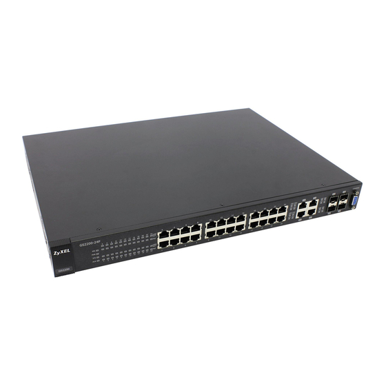
H A PT ER Hardware Panels 3.1 Overview This chapter describes the front panel and rear panel of the Switch and shows you how to make the hardware connections. 3.2 Front Panels The following figure shows the front panel of the Switch. Figure 9 Front Panel (GS2200-8) LEDs Console Port... - Page 26 Chapter 3 Hardware Panels Figure 11 Front Panel (GS2200-24) LEDs Console Port Dual Personality Interfaces Ethernet Ports Figure 12 Front Panel (GS2200-24P) LEDs Console Port Dual Personality Interfaces PoE Ethernet Ports The following table describes the port labels on the front panel. Table 2 Front Panel Connections LABEL DESCRIPTION...
-
Page 27: Console Port
Chapter 3 Hardware Panels Table 2 Front Panel Connections (continued) LABEL DESCRIPTION 2 or 4 Dual Each interface has one 100/1000 Mbps RJ-45 port and one Small Form-Factor Pluggable Personality (SFP) slot (also called a mini-GBIC slot), with one port or transceiver active at a time. Interfaces Note: The ports change to fiber mode directly when inserting the fiber module. -
Page 28: Mini-Gbic Slots
Chapter 3 Hardware Panels signal on the cable and using half duplex mode. When the Switch’s auto-negotiation is turned off, an Ethernet port uses the pre-configured speed and duplex mode when making a connection, thus requiring you to make sure that the settings of the peer Ethernet port are the same in order to connect. -
Page 29: Power Connector
Chapter 3 Hardware Panels Connect the fiber optic cables to the transceiver. Figure 13 Transceiver Installation Example Figure 14 Connecting the Fiber Optic Cables 3.2.3.2 Transceiver Removal Use the following steps to remove a mini-GBIC transceiver (SFP module). Remove the fiber optic cables from the transceiver. Open the transceiver’s latch (latch styles vary). -
Page 30: Leds
Chapter 3 Hardware Panels To connect power to the Switch, insert the female end of the power cord to the AC power receptacle on the front panel. Connect the other end of the supplied power cord to a power outlet. Make sure that no objects obstruct the airflow of the fans (located on the side of the unit). -
Page 31: Technical Reference
Technical Reference... -
Page 33: The Web Configurator
1234. The date and time display as shown if you have not configured a time server nor manually entered a time and date in the General Setup screen. Figure 18 Web Configurator: Login Click OK to view the first web configurator screen. GS2200 Series User’s Guide... -
Page 34: The Status Screen
Switch that stays the same even if the Switch’s power is turned off. C - Click this link to go to the status page of the Switch. D - Click this link to logout of the web configurator. GS2200 Series User’s Guide... - Page 35 This link takes you to a screen where you can configure settings for individual Switch ports. (For GS2200-8HP or GS2200-24P only) This link takes you to a screen where you can set priorities so that the Switch is able to reserve and allocate power to certain PDs. Advanced Application GS2200 Series User’s Guide...
- Page 36 This link takes you to a screen where you can configure CPU protection and error disable recovery. IP Application Static Routing This link takes you to a screen where you can configure static routes. A static route defines how the Switch should forward traffic by configuring the TCP/IP parameters manually. GS2200 Series User’s Guide...
- Page 37 This link takes you to a screen where you can view the MAC addresses – IP address resolution table. Configure Clone This link takes you to a screen where you can copy attributes of one port to other ports. GS2200 Series User’s Guide...
-
Page 38: Change Your Password
Note: Use the Save link when you are done with a configuration session. 4.5 Switch Lockout You could block yourself (and all others) from managing the Switch if you do one of the following: Delete the management VLAN (default is VLAN 1). GS2200 Series User’s Guide... -
Page 39: Resetting The Switch
Wait for the “Starting XMODEM upload” message before activating XMODEM upload on your terminal. After a configuration file upload, type atgo to restart the Switch. The Switch is now reinitialized with a default configuration file including the default password of “1234”. GS2200 Series User’s Guide... -
Page 40: Logging Out Of The Web Configurator
Figure 21 Web Configurator: Logout Screen 4.8 Help The web configurator’s online help has descriptions of individual screens and some supplementary information. Click the Help link from a web configurator screen to view an online help description of that screen. GS2200 Series User’s Guide... -
Page 41: Initial Setup Example
VLANs confine broadcast frames to the VLAN group in which the port(s) belongs. You can do this with port-based VLAN or tagged static VLAN with fixed port members. In this example, you want to configure port 1 as a member of VLAN 2. Figure 22 Initial Setup Network Example: VLAN GS2200 Series User’s Guide... -
Page 42: Setting Port Vid
Switch’s power is turned off. 5.1.2 Setting Port VID Use PVID to add a tag to incoming untagged frames received on that port so that the frames are forwarded to the VLAN group that the tag defines. GS2200 Series User’s Guide... -
Page 43: Configuring Switch Management Ip Address
The default management IP address of the Switch is 192.168.1.1. You can configure another IP address in a different subnet for management purposes. The following figure shows an example. Figure 24 Initial Setup Example: Management IP Address GS2200 Series User’s Guide... - Page 44 This is the same as the VLAN ID you configure in the Static VLAN screen. Click Add to save your changes back to the run- time memory. Settings in the run-time memory are lost when the Switch’s power is turned off. GS2200 Series User’s Guide...
-
Page 45: Tutorials
1 and 100 DHCP Client (B) 1 and 100 DHCP Client (C) 1 and 100 Access the Switch through http://192.168.1.1 by default. Log into the Switch by entering the username (default: admin) and password (default: 1234). GS2200 Series User’s Guide... - Page 46 Go to Advanced Application > VLAN > VLAN Port Setting, and set the PVID of the ports 5, 6 and 7 to 100. This tags untagged incoming frames on ports 5, 6 and 7 with the tag 100. Figure 27 Tutorial: Tag Untagged Frames GS2200 Series User’s Guide...
- Page 47 5 because the DHCP server is connected to port 5. Keep ports 6 and 7 Untrusted because they are connected to DHCP clients. Click Apply. Tutorial: Set the DHCP Server Port to Trusted Figure 29 GS2200 Series User’s Guide...
-
Page 48: How To Use Dhcp Relay On The Switch
This tutorial describes how to configure your Switch to forward DHCP client requests to a specific DHCP server. The DHCP server can then assign a specific IP address based on the information in the DHCP requests. GS2200 Series User’s Guide... -
Page 49: Dhcp Relay Tutorial Introduction
DHCP Server Port 2 192.168.2.3 PVID=102 VLAN 102 172.16.1.18 6.3.2 Creating a VLAN Follow the steps below to configure port 2 as a member of VLAN 102. Access the web configurator through the Switch’s management port. GS2200 Series User’s Guide... - Page 50 Name field and enter 102 in the VLAN Group ID field. Select Fixed to configure port 2 to be a permanent member of this VLAN. Clear the TX Tagging check box to set the Switch to remove VLAN tags before sending. GS2200 Series User’s Guide...
- Page 51 Figure 35 Tutorial: Click the VLAN Port Setting Link Enter 102 in the PVID field for port 2 to add a tag to incoming untagged frames received on that port so that the frames are forwarded to the VLAN group that the tag defines. GS2200 Series User’s Guide...
-
Page 52: Configuring Dhcp Relay
Click IP Application > DHCP and then the Global link to open the DHCP Relay screen. Select the Active check box. Enter the DHCP server’s IP address (192.168.2.3 in this example) in the Remote DHCP Server 1 field. Select the Option 82 and the Information check boxes. GS2200 Series User’s Guide... -
Page 53: Troubleshooting
You configured the correct VLAN ID, port number and system name for DHCP relay on both the DHCP server and the Switch. You clicked the Save link on the Switch to have your settings take effect. GS2200 Series User’s Guide... -
Page 54: System Status And Port Statistics
7.1.1 What You Can Do • Use the Port Status Summary screen (Section 7.2 on page 55) to view the port statistics. • Use the Port Details screen (Section 7.2.1 on page 57) to display individual port statistics. GS2200 Series User’s Guide... -
Page 55: Port Status Summary
This identifies the Ethernet port. Click a port number to display the Port Details screen (refer to Figure 40 on page 57). Name This is the name you assigned to this port in the Basic Setting > Port Setup screen. GS2200 Series User’s Guide... - Page 56 This field shows the total amount of time in hours, minutes and seconds the port has been Clear Counter Enter a port number and then click Clear Counter to erase the recorded statistical information for that port, or select Any to clear statistics for all ports. GS2200 Series User’s Guide...
-
Page 57: Status: Port Details
This field displays the name of the port. Link This field displays the speed (either 100M for 100Mbps or 1000M for 1000Mbps) and the duplex (F for full duplex or H for half duplex). It also shows the cable type (Copper or Fiber). GS2200 Series User’s Guide... - Page 58 This field shows the number of packets (including bad packets) received that were 64 octets in length. 65-127 This field shows the number of packets (including bad packets) received that were between 65 and 127 octets in length. GS2200 Series User’s Guide...
- Page 59 This field shows the number of packets (including bad packets) received that were between 1519 octets and the maximum frame size. The maximum frame size varies depending on your switch model. See Chapter 43 on page 307. GS2200 Series User’s Guide...
-
Page 60: Basic Setting
PDs are receiving from the Switch and use the PoE Setup screen (Section 8.8.1 on page 73) to set the priority levels for the Switch in distributing power to PDs. (These screens are available to GS2200-8HP and GS2200-24P only.) GS2200 Series User’s Guide... -
Page 61: System Information
This field displays the minimum temperature measured at this sensor. Threshold This field displays the upper temperature limit at this sensor. Status This field displays Normal for temperatures below the threshold and Error for those above. GS2200 Series User’s Guide... - Page 62 This field displays the minimum voltage measured at this point. Threshold This field displays the percentage tolerance of the voltage with which the Switch still works. Status Normal indicates that the voltage is within an acceptable operating range at this point; otherwise Error is displayed. GS2200 Series User’s Guide...
-
Page 63: General Setup
60 seconds. If you select a timeserver that is unreachable, then this screen will appear locked for 60 seconds. Please wait. Current Time This field displays the time you open this menu (or refresh the menu). GS2200 Series User’s Guide... -
Page 64: Introduction To Vlans
When properly configured, VLAN prevents one subscriber from accessing the network resources of another on the same LAN, thus a user will not see the printers and hard disks of another user in the same building. GS2200 Series User’s Guide... -
Page 65: Switch Setup Screen
GARP Timer: Switches join VLANs by making a declaration. A declaration is made by issuing a Join message using GARP. Declarations are withdrawn by issuing a Leave message. A Leave All message terminates all registrations. GARP timers set declaration timeout values. See the chapter on VLAN setup for more background information. GS2200 Series User’s Guide... -
Page 66: Ip Setup
Use the IP Setup screen to configure the Switch IP address, default gateway device, the default domain name server and the management VLAN ID. The default gateway specifies the IP address of the default gateway (next hop) for outgoing traffic. GS2200 Series User’s Guide... -
Page 67: Management Ip Addresses
DNS (Domain Name System) is for mapping a domain name to its corresponding IP Server address and vice versa. Enter a domain name server IP address in order to be able to use a domain name instead of an IP address. Default Management IP Address GS2200 Series User’s Guide... - Page 68 This field displays the IP address of the default gateway. Delete Check the management IP addresses that you want to remove in the Delete column, then click the Delete button. Cancel Click Cancel to clear the selected check boxes in the Delete column. GS2200 Series User’s Guide...
-
Page 69: Port Setup
Enter a descriptive name that identifies this port. You can enter up to 64 alpha-numerical characters. Note: Due to space limitation, the port name may be truncated in some web configurator screens. Type This field displays 10/100M for Fast Ethernet connections and 10/100/1000M for Gigabit connections. GS2200 Series User’s Guide... -
Page 70: Poe Status
Click Cancel to begin configuring this screen afresh. 8.8 PoE Status Note: The following screens are available for the GS2200-8HP or GS2200-24P model only. Some features are only available for the Ethernet ports (1 to 8 or 1 to 24). GS2200 Series User’s Guide... - Page 71 Note: The RPS connector port at the back panel of the GS2200-24P and RPS connector cable should only be used with the PPS250. Do not insert other connector cables to the RPS connector port of the GS2200-24P or the PPS250. GS2200 Series User’s Guide...
- Page 72 This field shows which ports can receive power from the Switch. You can set this in Section 8.8.1 on page • Disable - The PD connected to this port cannot get power supply. • Enable - The PD connected to this port can receive power. GS2200 Series User’s Guide...
-
Page 73: Poe Setup
This field displays the maximum amount of current drawn by the PD from the Switch on this (mA) port. 8.8.1 PoE Setup Use this screen to set the priority levels for the Switch in distributing power to PDs. GS2200 Series User’s Guide... - Page 74 Select High to set the Switch to assign the remaining power to the port after all critical priority ports are served. Select Low to set the Switch to assign the remaining power to the port after all critical and high priority ports are served. GS2200 Series User’s Guide...
- Page 75 Save link on the top navigation panel to save your changes to the non-volatile memory when you are done configuring. Cancel Click Cancel to begin configuring this screen afresh. GS2200 Series User’s Guide...
- Page 76 Chapter 8 Basic Setting GS2200 Series User’s Guide...
-
Page 77: Vlan
The remaining twelve bits define the VLAN ID, giving a possible maximum number of 4,096 VLANs. Note that user priority and VLAN ID are independent of each other. A frame with VID (VLAN Identifier) of null (0) is called a priority frame, meaning that only the priority GS2200 Series User’s Guide... - Page 78 Please refer to the following table for common IEEE 802.1Q VLAN terminology. Table 16 IEEE 802.1Q VLAN Terminology VLAN PARAMETER TERM DESCRIPTION VLAN Type Permanent VLAN This is a static VLAN created manually. Dynamic VLAN This is a VLAN configured by a GVRP registration/ deregistration process. GS2200 Series User’s Guide...
-
Page 79: Port Vlan Trunking
1 and 2 (VLAN groups that are unknown to those switches) to pass through their VLAN trunking port(s). Figure 49 Port VLAN Trunking 9.1.2.3 Select the VLAN Type Select a VLAN type in the Basic Setting > Switch Setup screen. Figure 50 Switch Setup > Select VLAN Type GS2200 Series User’s Guide... -
Page 80: Vlan Status
This is the VLAN identification number that was configured in the Static VLAN screen. Elapsed Time This field shows how long it has been since a normal VLAN was registered or a static VLAN was set up. GS2200 Series User’s Guide... -
Page 81: Vlan Details
This field shows how long it has been since a normal VLAN was registered or a static VLAN was set up. Status This field shows how this VLAN was added to the Switch. dynamic: using GVRP static: added as a permanent entry GS2200 Series User’s Guide... -
Page 82: Configure A Static Vlan
64 printable characters. VLAN Group ID Enter the VLAN ID for this static entry; the valid range is between 1 and 4094. Port The port number identifies the port you are configuring. GS2200 Series User’s Guide... - Page 83 This field indicates whether the VLAN settings are enabled (Yes) or disabled (No). Name This field displays the descriptive name for this VLAN group. Delete Click Delete to remove the selected entry from the summary table. Cancel Click Cancel to clear the Delete check boxes. GS2200 Series User’s Guide...
-
Page 84: Configure Vlan Port Settings
Use this row only if you want to make some settings the same for all ports. Use this row first to set the common settings and then make adjustments on a port-by-port basis. Note: Changes in this row are copied to all the ports as soon as you make them. GS2200 Series User’s Guide... -
Page 85: Subnet Based Vlans
172.16.1.0/24 (voice services). You also have a subnet based VLAN with priority 5 and VID of 200 for traffic received from IP subnet 192.168.1.0/24 (video services). Lastly, you configure VLAN with priority 3 and VID of 300 for traffic received from IP subnet 10.1.1.0/24 (data services). All GS2200 Series User’s Guide... -
Page 86: Configuring Subnet Based Vlan
Note: Subnet based VLAN applies to un-tagged packets and is applicable only when you use IEEE 802.1Q tagged VLAN. Note: You can not enable subnet-based VLANs on the Switch when the Guest VLAN feature is activated on a port. GS2200 Series User’s Guide... - Page 87 Save link on the top navigation panel to save your changes to the non-volatile memory when you are done configuring. Cancel Click Cancel to begin configuring this screen afresh. GS2200 Series User’s Guide...
-
Page 88: Protocol Based Vlans
C. Figure 57 Protocol Based VLAN Application Example 9.6.1 Configuring Protocol Based VLAN Click Protocol Based VLAN in the VLAN Port Setting screen to display the configuration screen as shown. GS2200 Series User’s Guide... - Page 89 This is the index number identifying this protocol based VLAN. Click on any of these numbers to edit an existing protocol based VLAN. Active This field shows whether the protocol based VLAN is active or not. Port This field shows which port belongs to this protocol based VLAN. GS2200 Series User’s Guide...
-
Page 90: Port-Based Vlan Setup
Note: In screens (such as IP Setup and Filtering) that require a VID, you must enter 1 as the VID. The port-based VLAN setup screen is shown next. The CPU management port forms a VLAN with all Ethernet ports. GS2200 Series User’s Guide... -
Page 91: Configure A Port-Based Vlan
Select Port Based as the VLAN Type in the Basic Setting > Switch Setup screen and then click Advanced Application > VLAN from the navigation panel to display the next screen. Figure 59 Port Based VLAN Setup (All Connected) GS2200 Series User’s Guide... - Page 92 Chapter 9 VLAN Figure 60 Port Based VLAN Setup (Port Isolation) GS2200 Series User’s Guide...
-
Page 93: Technical Reference
Give this protocol-based VLAN a descriptive name. Type IP-VLAN. Select the protocol. Leave the default value IP. Type the VLAN ID of an existing VLAN. In our example we already created a static VLAN with an ID of 5. Type 5. GS2200 Series User’s Guide... - Page 94 To add more ports to this protocol based VLAN. Click the index number of the protocol based VLAN entry. Click 1 Change the value in the Port field to the next port you want to add. Click Add. GS2200 Series User’s Guide...
-
Page 95: Static Mac Forward Setup
Chapter 19 on page 145 for more information on port security. Click Advanced Application > Static MAC Forwarding in the navigation panel to display the configuration screen as shown. Figure 62 Advanced Application > Static MAC Forwarding GS2200 Series User’s Guide... - Page 96 This field displays the port where the MAC address shown in the next field will be forwarded. Delete Click Delete to remove the selected entry from the summary table. Cancel Click Cancel to clear the Delete check boxes. GS2200 Series User’s Guide...
-
Page 97: Static Multicast Forward Setup
You can configure this in the Advanced Application > Multicast > Multicast Setting screen (see Section 23.3 on page 165). Figure 63 shows such unknown multicast frames flooded to all ports. With static multicast forwarding, you can forward these multicasts to port(s) GS2200 Series User’s Guide... -
Page 98: Configuring Static Multicast Forwarding
Figure 64 Static Multicast Forwarding to A Single Port Figure 65 Static Multicast Forwarding to Multiple Ports 11.2 Configuring Static Multicast Forwarding Use this screen to configure rules to forward specific multicast frames, such as streaming or control frames, to specific port(s). GS2200 Series User’s Guide... - Page 99 MAC Address This field displays the multicast MAC address that identifies a multicast group. This field displays the ID number of a VLAN group to which frames containing the specified multicast MAC address will be forwarded. GS2200 Series User’s Guide...
- Page 100 This field displays the port(s) within a identified VLAN group to which frames containing the specified multicast MAC address will be forwarded. Delete Click Delete to remove the selected entry from the summary table. Cancel Click Cancel to clear the Delete check boxes. GS2200 Series User’s Guide...
-
Page 101: Filtering
12.2 Configure a Filtering Rule Use this screen to create rules for traffic going through the Switch. Click Advanced Application > Filtering in the navigation panel to display the screen as shown next. Figure 67 Advanced Application > Filtering GS2200 Series User’s Guide... - Page 102 This field displays the filter type for the MAC address. Delete Check the rule(s) that you want to remove in the Delete column and then click the Delete button. Cancel Click Cancel to clear the selected checkbox(es) in the Delete column. GS2200 Series User’s Guide...
-
Page 103: Spanning Tree Protocol
• Use the Multiple Spanning Tree Protocol Status screen (Section 13.9 on page 117) to view the MSTP status. 13.1.2 What You Need to Know Read on for concepts on STP that can help you configure the screens in this chapter. GS2200 Series User’s Guide... - Page 104 LAN topology changes, a new spanning tree is constructed. Once a stable network topology has been established, all bridges listen for Hello BPDUs (Bridge Protocol Data Units) transmitted from the root bridge. If a bridge does not get a Hello BPDU after a GS2200 Series User’s Guide...
-
Page 105: Stp Port States
In the following example, there are two RSTP instances (MRSTP 1 and MRSTP2) on switch A. To set up MRSTP, activate MRSTP on the Switch and specify which port(s) belong to which spanning tree. Note: Each port can belong to one STP tree only. Figure 68 MRSTP Network Example GS2200 Series User’s Guide... -
Page 106: Spanning Tree Protocol Status Screen
This screen differs depending on which STP mode (RSTP, MRSTP or MSTP) you configure on the Switch. This screen is described in detail in the section that follows the configuration section for each STP mode. Click Configuration to activate one of the STP standards on the Switch. GS2200 Series User’s Guide... -
Page 107: Spanning Tree Configuration
Save link on the top navigation panel to save your changes to the non-volatile memory when you are done configuring. Cancel Click Cancel to begin configuring this screen afresh. GS2200 Series User’s Guide... -
Page 108: Configure Rapid Spanning Tree Protocol
Select a value from the drop-down list box. The lower the numeric value you assign, the higher the priority for this bridge. Bridge Priority determines the root bridge, which in turn determines Hello Time, Max Age and Forwarding Delay. GS2200 Series User’s Guide... -
Page 109: Rapid Spanning Tree Protocol Status
13.5 Rapid Spanning Tree Protocol Status Click Advanced Application > Spanning Tree Protocol in the navigation panel to display the status screen as shown next. See Section 13.1 on page 103 for more information on RSTP. GS2200 Series User’s Guide... - Page 110 Spanning Tree. Topology Changed This is the number of times the spanning tree has been reconfigured. Times Time Since Last This is the time since the spanning tree was last reconfigured. Change GS2200 Series User’s Guide...
-
Page 111: Configure Multiple Rapid Spanning Tree Protocol
Select a value from the drop-down list box. The lower the numeric value you assign, the higher the priority for this bridge. Bridge Priority determines the root bridge, which in turn determines Hello Time, Max Age and Forwarding Delay. GS2200 Series User’s Guide... -
Page 112: Multiple Rapid Spanning Tree Protocol Status
13.7 Multiple Rapid Spanning Tree Protocol Status Click Advanced Application > Spanning Tree Protocol in the navigation panel to display the status screen as shown next. See Section 13.1 on page 103 for more information on MRSTP. GS2200 Series User’s Guide... - Page 113 Spanning Tree. Topology Changed This is the number of times the spanning tree has been reconfigured. Times Time Since Last This is the time since the spanning tree was last reconfigured. Change GS2200 Series User’s Guide...
-
Page 114: Configure Multiple Spanning Tree Protocol
13.8 Configure Multiple Spanning Tree Protocol To configure MSTP, click MSTP in the Advanced Application > Spanning Tree Protocol screen. Multiple STP on page 106 for more information on MSTP. Figure 75 Advanced Application > Spanning Tree Protocol > MSTP GS2200 Series User’s Guide... - Page 115 Switch will be chosen as the root bridge within the spanning tree instance. Enter priority values between 0 and 61440 in increments of 4096 (thus valid values are 4096, 8192, 12288, 16384, 20480, 24576, 28672, 32768, 36864, 40960, 45056, 49152, 53248, 57344 and 61440). GS2200 Series User’s Guide...
- Page 116 This field display the ports configured to participate in the MST instance. Delete Check the rule(s) that you want to remove in the Delete column and then click the Delete button. Cancel Click Cancel to begin configuring this screen afresh. GS2200 Series User’s Guide...
-
Page 117: Multiple Spanning Tree Protocol Port Configuration
13.9 Multiple Spanning Tree Protocol Status Click Advanced Application > Spanning Tree Protocol in the navigation panel to display the status screen as shown next. See Multiple STP on page 106 for more information on MSTP. GS2200 Series User’s Guide... - Page 118 This is the time (in seconds) the root switch will wait before changing states (that is, (second) listening to learning to forwarding). Cost to Bridge This is the path cost from the root port on this Switch to the root switch. GS2200 Series User’s Guide...
-
Page 119: Technical Reference
This is the priority and number of the port on the Switch through which this Switch must communicate with the root of the MST instance. 13.10 Technical Reference This section provides technical background information on the topics discussed in this chapter. GS2200 Series User’s Guide... -
Page 120: Mstp Network Example
Each MSTP-enabled device can only belong to one MST region. When BPDUs enter an MST region, external path cost (of paths outside this region) is increased by one. Internal path cost (of paths within this region) is increased by one when BPDUs traverse the region. GS2200 Series User’s Guide... -
Page 121: Mst Instance
A CIST represents the connectivity of the entire network and it is equivalent to a spanning tree in an STP/RSTP. The CIST is the default MST instance (MSTID 0). Any VLANs that are not members of an MST instance are members of the CIST. In an MSTP-enabled network, there is only one CIST GS2200 Series User’s Guide... - Page 122 Chapter 13 Spanning Tree Protocol that runs between MST regions and single spanning tree devices. A network may contain multiple MST regions and other network segments running RSTP. Figure 81 MSTP and Legacy RSTP Network Example GS2200 Series User’s Guide...
-
Page 123: Bandwidth Control
Bandwidth control means defining a maximum allowable bandwidth for out-going traffic flows on a port. 14.1.1 What You Can Do Use the Bandwidth Control screen (Section 14.2 on page 124) to limit the bandwidth for traffic going through the Switch. GS2200 Series User’s Guide... -
Page 124: Bandwidth Control Setup
Note: Ingress rate bandwidth control applies to layer 2 traffic only. Active Select this check box to activate egress rate limits on this port. Egress Specify the maximum bandwidth allowed in kilobits per second (Kbps) for the out-going traffic Rate flow on a port. GS2200 Series User’s Guide... - Page 125 Save link on the top navigation panel to save your changes to the non-volatile memory when you are done configuring. Cancel Click Cancel to reset the fields. GS2200 Series User’s Guide...
-
Page 126: Broadcast Storm Control
15.1.1 What You Can Do Use the Broadcast Storm Control screen (Section 15.2 on page 127) to limit the number of broadcast, multicast and destination lookup failure (DLF) packets the Switch receives per second on the ports. GS2200 Series User’s Guide... -
Page 127: Broadcast Storm Control Setup
Save link on the top navigation panel to save your changes to the non-volatile memory when you are done configuring. Cancel Click Cancel to reset the fields. GS2200 Series User’s Guide... -
Page 128: Mirroring
16.1.1 What You Can Do Use the Mirroring screen (Section 16.2 on page 129) to select a monitor port and specify the traffic flow to be copied to the monitor port. GS2200 Series User’s Guide... -
Page 129: Port Mirroring Setup
Note: Changes in this row are copied to all the ports as soon as you make them. Mirrored Select this option to mirror the traffic on a port. Direction Specify the direction of the traffic to mirror by selecting from the drop-down list box. Choices are Egress (outgoing), Ingress (incoming) and Both. GS2200 Series User’s Guide... - Page 130 Save link on the top navigation panel to save your changes to the non-volatile memory when you are done configuring. Cancel Click Cancel to reset the fields. GS2200 Series User’s Guide...
-
Page 131: Link Aggregation
When you enable LACP link aggregation on a port, the port can automatically negotiate with the ports at the remote end of a link to establish trunk groups. LACP also allows port redundancy, that GS2200 Series User’s Guide... -
Page 132: Link Aggregation Status
Section 17.1 on page 131 for more information. Figure 85 Advanced Application > Link Aggregation Status Port Priority and Port Number are 0 as it is the aggregator ID for the trunk group, not the individual port. GS2200 Series User’s Guide... - Page 133 This field displays how these ports were added to the trunk group. It displays: • Static - if the ports are configured as static members of a trunk group. • LACP - if the ports are configured to join a trunk group via LACP. GS2200 Series User’s Guide...
-
Page 134: Link Aggregation Setting
This is the only screen you need to configure to enable static link aggregation. Aggregation Setting Group ID The field identifies the link aggregation group, that is, one logical link containing multiple ports. Active Select this option to activate a trunk group. GS2200 Series User’s Guide... - Page 135 Save link on the top navigation panel to save your changes to the non-volatile memory when you are done configuring. Cancel Click Cancel to begin configuring this screen afresh. GS2200 Series User’s Guide...
-
Page 136: Link Aggregation Control Protocol
Table 44 Advanced Application > Link Aggregation > Link Aggregation Setting > LACP LABEL DESCRIPTION Link Note: Do not configure this screen unless you want to enable dynamic link aggregation. Aggregation Control Protocol Active Select this checkbox to enable Link Aggregation Control Protocol (LACP). GS2200 Series User’s Guide... -
Page 137: Technical Reference
Click Cancel to begin configuring this screen afresh. 17.5 Technical Reference This section provides technical background information on the topics discussed in this chapter. 17.5.1 Static Trunking Example This example shows you how to create a static port trunk group for ports 2-5. GS2200 Series User’s Guide... - Page 138 Click Apply when you are done. Figure 89 Trunking Example - Configuration Screen Your trunk group 1 (T1) configuration is now complete. GS2200 Series User’s Guide...
-
Page 139: Port Authentication
At the time of writing, IEEE 802.1x is not supported by all operating systems. See your operating system documentation. If your operating system does not support 802.1x, then you may need to install 802.1x client software. GS2200 Series User’s Guide... -
Page 140: Port Authentication Configuration
RADIUS server settings in the Auth and Acct > Radius Server Setup screen. Click Advanced Application > Port Authentication in the navigation panel to display the screen as shown. Figure 91 Advanced Application > Port Authentication GS2200 Series User’s Guide... -
Page 141: Activate Ieee 802.1X Security
Switch blocks the client from accessing the port or sends the client to the Guest VLAN when a Guest VLAN is enabled on the port. The client needs to send a new request to be authenticated by the Switch again. GS2200 Series User’s Guide... -
Page 142: Guest Vlan
802.1x screen click Guest Vlan to display the configuration screen as shown. Note: You can not enable the Guest VLAN feature on a port when a subnet-based VLAN or protocol-based VLAN is activated on the Switch. GS2200 Series User’s Guide... - Page 143 VLAN. Once the first user who did authentication logs out or disconnects from the port, rest of the users are blocked until a user does the authentication process again. Select Multi-Secure to authenticate each user that connects to this port. GS2200 Series User’s Guide...
- Page 144 Save link on the top navigation panel to save your changes to the non-volatile memory when you are done configuring. Cancel Click Cancel to begin configuring this screen afresh. GS2200 Series User’s Guide...
-
Page 145: Port Security
19.1.1 What You Can Do Use the Port Security screen (Section 19.2 on page 146) to enable port security and disable MAC address learning. You can also enable the port security feature on a port. GS2200 Series User’s Guide... -
Page 146: Port Security Setup
Use this row only if you want to make some settings the same for all ports. Use this row first to set the common settings and then make adjustments on a port-by-port basis. Note: Changes in this row are copied to all the ports as soon as you make them. GS2200 Series User’s Guide... - Page 147 Save link on the top navigation panel to save your changes to the non-volatile memory when you are done configuring. Cancel Click Cancel to begin configuring this screen afresh. GS2200 Series User’s Guide...
-
Page 148: Classifier
Use the Classifier screen to define the classifiers. After you define the classifier, you can specify actions (or policy) to act upon the traffic that matches the rules. To configure policy rules, refer to Chapter 21 on page 154. GS2200 Series User’s Guide... - Page 149 To specify a source, select the second choice and type a MAC address in valid MAC address format (six hexadecimal character pairs). Port Type the port number to which the rule should be applied. You may choose one port only or all ports (Any). GS2200 Series User’s Guide...
-
Page 150: Viewing And Editing Classifier Configuration
20.2.1 Viewing and Editing Classifier Configuration To view a summary of the classifier configuration, scroll down to the summary table at the bottom of the Classifier screen. To change the settings of a rule, click a number in the Index field. GS2200 Series User’s Guide... - Page 151 In the Internet Protocol there is a field, called “Protocol”, to identify the next level protocol. The following table shows some common protocol types and the corresponding protocol number. Refer http://www.iana.org/assignments/protocol-numbers for a complete list. Table 51 Common IP Protocol Types and Protocol Numbers PROTOCOL TYPE PROTOCOL NUMBER ICMP GS2200 Series User’s Guide...
-
Page 152: Classifier Example
Appendix B on page 303 for information on commonly used port numbers. 20.3 Classifier Example The following screen shows an example where you configure a classifier that identifies all traffic from MAC address 00:50:ba:ad:4f:81 on port 2. GS2200 Series User’s Guide... - Page 153 Chapter 20 Classifier After you have configured a classifier, you can configure a policy (in the Policy screen) to define action(s) on the classified traffic flow. Figure 98 Classifier: Example GS2200 Series User’s Guide...
-
Page 154: Policy Rule
154) to enable the policy and display the active classifier(s) you configure in the Classifier screen. 21.2 Configuring Policy Rules You must first configure a classifier in the Classifier screen. Refer to Section 20.2 on page 148 more information. GS2200 Series User’s Guide... - Page 155 Set the fields below for this policy. You only have to set the field(s) that is related to the action(s) you configure in the Action field. General VLAN ID Specify a VLAN ID number. Egress Port Type the number of an outgoing port. Priority Specify a priority level. GS2200 Series User’s Guide...
- Page 156 This field displays the name you have assigned to this policy. Classifier(s) This field displays the name(s) of the classifier to which this policy applies. Delete Click Delete to remove the selected entry from the summary table. GS2200 Series User’s Guide...
-
Page 157: Viewing And Editing Policy Configuration
To view a summary of the classifier configuration, scroll down to the summary table at the bottom of the Policy screen. To change the settings of a rule, click a number in the Index field. Figure 100 Advanced Application > Policy Rule: Summary Table GS2200 Series User’s Guide... -
Page 158: Policy Example
The figure below shows an example Policy screen where you configure a policy to limit bandwidth on a traffic flow classified using the Example classifier (refer to Section 20.3 on page 152). Figure 101 Policy Example GS2200 Series User’s Guide... -
Page 159: Queuing Method
A queue is a given an amount of bandwidth irrespective of the incoming traffic on that port. This queue then moves to the back of the list. The next queue is given GS2200 Series User’s Guide... -
Page 160: Configuring Queuing
Use this screen to set priorities for the queues of the Switch. This distributes bandwidth across the different traffic queues. Click Advanced Application > Queuing Method in the navigation panel. Figure 102 Advanced Application > Queuing Method GS2200 Series User’s Guide... - Page 161 Save link on the top navigation panel to save your changes to the non-volatile memory when you are done configuring. Cancel Click Cancel to begin configuring this screen afresh. GS2200 Series User’s Guide...
-
Page 162: Multicast
(see the IANA web site for more information). IGMP Snooping A Switch can passively snoop on IGMP packets transferred between IP multicast routers/switches and IP multicast hosts to learn the IP multicast group membership. It checks IGMP packets passing GS2200 Series User’s Guide... - Page 163 In MVR, a source port is a port on the Switch that can send and receive multicast traffic in a multicast VLAN while a receiver port can only receive multicast traffic. Once configured, the Switch maintains a forwarding table that matches the multicast stream to the associated multicast group. GS2200 Series User’s Guide...
-
Page 164: Multicast Status
23.2 Multicast Status Click Advanced Applications > Multicast to display the screen as shown. This screen shows the multicast group information. See Section 23.1 on page 162 for more information on multicasting. Figure 105 Advanced Application > Multicast GS2200 Series User’s Guide... -
Page 165: Multicast Setting
23.3 Multicast Setting Click Advanced Applications > Multicast > Multicast Setting link to display the screen as shown. See Section 23.1 on page 162 for more information on multicasting. Figure 106 Advanced Application > Multicast > Multicast Setting GS2200 Series User’s Guide... - Page 166 This defines how many seconds the Switch waits for an IGMP report before removing an IGMP snooping membership entry when an IGMP leave message is received on this port from a host. Group Limited Select this option to limit the number of multicast groups this port is allowed to join. GS2200 Series User’s Guide...
- Page 167 Save link on the top navigation panel to save your changes to the non-volatile memory when you are done configuring. Cancel Click Cancel to begin configuring this screen afresh. GS2200 Series User’s Guide...
-
Page 168: Igmp Snooping Vlan
Switch’s run-time memory. The Switch loses these changes if it is turned off or loses power, so use the Save link on the top navigation panel to save your changes to the non- volatile memory when you are done configuring. GS2200 Series User’s Guide... -
Page 169: Igmp Filtering Profile
To configure additional rule(s) for a profile that you have already added, enter the profile name and specify a different IP multicast address range. Start Address Type the starting multicast IP address for a range of multicast IP addresses that you want to belong to the IGMP filter profile. GS2200 Series User’s Guide... -
Page 170: The Mvr Screen
VLAN. Click Advanced Applications > Multicast > Multicast Setting > MVR link to display the screen as shown next. Note: You can create up to three multicast VLANs and up to 256 multicast rules on the Switch. GS2200 Series User’s Guide... - Page 171 Use this row only if you want to make some settings the same for all ports. Use this row first to set the common settings and then make adjustments on a port-by-port basis. Note: Changes in this row are copied to all the ports as soon as you make them. GS2200 Series User’s Guide...
-
Page 172: Mvr Group Configuration
Configuration in the MVR screen. Note: A port can belong to more than one multicast VLAN. However, IP multicast group addresses in different multicast VLANs cannot overlap. Figure 110 Advanced Application > Multicast > Multicast Setting > MVR: Group Configuration GS2200 Series User’s Guide... -
Page 173: Mvr Configuration Example
1. In addition, port 7 belongs to the multicast group with VID 200 to receive multicast traffic (the News and Movie channels) from the remote streaming media server, S. Computers A, B and C in VLAN 1 are able to receive the traffic. Figure 111 MVR Configuration Example GS2200 Series User’s Guide... - Page 174 Chapter 23 Multicast To configure the MVR settings on the Switch, create a multicast group in the MVR screen and set the receiver and source ports. Figure 112 MVR Configuration Example GS2200 Series User’s Guide...
- Page 175 Group Configuration screen. The following figure shows an example where two multicast groups (News and Movie) are configured for the multicast VLAN 200. Figure 113 MVR Group Configuration Example Figure 114 MVR Group Configuration Example GS2200 Series User’s Guide...
-
Page 176: Aaa
Switch but user B cannot. The Switch can authorize users based on user accounts configured on the Switch itself or it can use an external server to authorize a large number of users. GS2200 Series User’s Guide... -
Page 177: Aaa Screens
Figure 116 Advanced Application > AAA 24.3 RADIUS Server Setup Use this screen to configure your RADIUS server settings. See Section on page 177 for more information on RADIUS servers and Section 24.6.2 on page 185 for RADIUS attributes utilized by GS2200 Series User’s Guide... - Page 178 Enter the IP address of an external RADIUS server in dotted decimal notation. UDP Port The default port of a RADIUS server for authentication is 1812. You need not change this value unless your network administrator instructs you to do so. GS2200 Series User’s Guide...
- Page 179 Save link on the top navigation panel to save your changes to the non-volatile memory when you are done configuring. Cancel Click Cancel to begin configuring this screen afresh. GS2200 Series User’s Guide...
-
Page 180: Tacacs+ Server Setup
TACACS+ server for 15 seconds and then tries the second TACACS+ server. Index This is a read-only number representing a TACACS+ server entry. IP Address Enter the IP address of an external TACACS+ server in dotted decimal notation. GS2200 Series User’s Guide... - Page 181 Save link on the top navigation panel to save your changes to the non-volatile memory when you are done configuring. Cancel Click Cancel to begin configuring this screen afresh. GS2200 Series User’s Guide...
-
Page 182: Aaa Setup
Method 2 and Method 3 fields. Select local to have the Switch check the access privilege configured for local authentication. Select radius or tacacs+ to have the Switch check the access privilege via the external servers. GS2200 Series User’s Guide... - Page 183 If you don’t select this and you have two accounting servers set up, then the Switch sends information to the first accounting server and if it doesn’t get a response from the accounting server then it tries the second accounting server. GS2200 Series User’s Guide...
-
Page 184: Technical Reference
• Vendor-Type: A vendor specified attribute, identifying the setting you want to modify. • Vendor-data: A value you want to assign to the setting. Note: Refer to the documentation that comes with your RADIUS server on how to configure VSAs for users authenticating via the RADIUS server. GS2200 Series User’s Guide... -
Page 185: Supported Radius Attributes
Refer to RFC 2865 for more information about RADIUS attributes used for authentication. This section lists the attributes used by authentication functions on the Switch. In cases where the attribute has a specific format associated with it, the format is specified. GS2200 Series User’s Guide... -
Page 186: Attributes Used For Authentication
24.6.3.2 Attributes Used to Login Users User-Name User-Password NAS-Identifier NAS-IP-Address 24.6.3.3 Attributes Used by the IEEE 802.1x Authentication User-Name NAS-Identifier NAS-IP-Address NAS-Port NAS-Port-Type - This value is set to Ethernet(15) on the Switch. Calling-Station-Id Frame-MTU EAP-Message State Message-Authenticator GS2200 Series User’s Guide... -
Page 187: Ip Source Guard
(Section 25.9 on page 201) to enable ARP inspection on the Switch. You can also configure the length of time the Switch stores records of discarded ARP packets and global settings for the ARP inspection log. GS2200 Series User’s Guide... -
Page 188: What You Need To Know
This field displays how many days, hours, minutes, and seconds the binding is valid; for example, 2d3h4m5s means the binding is still valid for 2 days, 3 hours, 4 minutes, and 5 seconds. This field displays infinity if the binding is always valid (for example, a static binding). GS2200 Series User’s Guide... -
Page 189: Ip Source Guard Static Binding
If you try to create a static binding with the same MAC address and VLAN ID as an existing static binding, the new static binding replaces the original one. To open this screen, click Advanced Application > IP Source Guard > Static Binding. Figure 121 IP Source Guard Static Binding GS2200 Series User’s Guide... -
Page 190: Dhcp Snooping
Click this to clear the Delete check boxes above. 25.4 DHCP Snooping Use this screen to look at various statistics about the DHCP snooping database. To open this screen, click Advanced Application > IP Source Guard > DHCP Snooping. GS2200 Series User’s Guide... - Page 191 This field displays how long (in seconds) the Switch waits to update the DHCP snooping database after the current bindings change. This section displays information about the current update and the next update of the DHCP snooping database. GS2200 Series User’s Guide...
- Page 192 MAC address and VLAN ID. Invalid interfaces This field displays the number of bindings the Switch ignored because the port number was a trusted interface or does not exist anymore. GS2200 Series User’s Guide...
-
Page 193: Dhcp Snooping Configure
Use this screen to enable DHCP snooping on the Switch (not on specific VLAN), specify the VLAN where the default DHCP server is located, and configure the DHCP snooping database. The DHCP snooping database stores the current bindings on a secure, external TFTP server so that they are GS2200 Series User’s Guide... - Page 194 In this case, the Switch waits to start the next update until it completes the current one. Agent URL Enter the location of the DHCP snooping database. The location should be expressed like this: tftp://{domain name or IP address}/directory, if applicable/file name; for example, tftp://192.168.10.1/database.txt. GS2200 Series User’s Guide...
-
Page 195: Dhcp Snooping Port Configure
25.5.1 DHCP Snooping Port Configure Use this screen to specify whether ports are trusted or untrusted ports for DHCP snooping. Note: If DHCP snooping is enabled but there are no trusted ports, DHCP requests cannot reach the DHCP server. GS2200 Series User’s Guide... - Page 196 Specify the maximum number for DHCP packets (1-2048) that the Switch receives from each port each second. The Switch discards any additional DHCP packets. Enter 0 to disable this limit, which is recommended for trusted ports. GS2200 Series User’s Guide...
-
Page 197: Dhcp Snooping Vlan Configure
DHCP VLAN, if specified, or VLAN. You can configure the system name in the General Setup screen. See Chapter 8 on page 60. You can specify the DHCP VLAN in the DHCP Snooping Configure screen. See Section 25.5 on page 193. GS2200 Series User’s Guide... -
Page 198: Arp Inspection Status
This field displays the source port of the discarded ARP packet. Expiry (sec) This field displays how long (in seconds) the MAC address filter remains in the Switch. You can also delete the record manually (Delete). GS2200 Series User’s Guide... -
Page 199: Arp Inspection Vlan Status
Click this to display the specified range of VLANs in the section below. This field displays the VLAN ID of each VLAN in the range specified above. Received This field displays the total number of ARP packets received from the VLAN since the Switch last restarted. GS2200 Series User’s Guide... -
Page 200: Arp Inspection Log Status
The Switch consolidates identical log messages generated by ARP packets in the log consolidation interval into one log message. You can configure this interval in the ARP Inspection Configure screen. See Section 25.9 on page 201. GS2200 Series User’s Guide... -
Page 201: Arp Inspection Configure
Switch stores records of discarded ARP packets and global settings for the ARP inspection log. To open this screen, click Advanced Application > IP Source Guard > ARP Inspection > Configure. Figure 129 ARP Inspection Configure GS2200 Series User’s Guide... -
Page 202: Arp Inspection Port Configure
25.9.1 ARP Inspection Port Configure Use this screen to specify whether ports are trusted or untrusted ports for ARP inspection. You can also specify the maximum rate at which the Switch receives ARP packets on each untrusted port. To GS2200 Series User’s Guide... - Page 203 Switch accepts a maximum of 15 ARP packets in every one-second interval. If the burst interval is 5 seconds, then the Switch accepts a maximum of 75 ARP packets in every five-second interval. Enter the length (1-15 seconds) of the burst interval. GS2200 Series User’s Guide...
-
Page 204: Arp Inspection Vlan Configure
This field displays the VLAN ID of each VLAN in the range specified above. If you configure the * VLAN, the settings are applied to all VLANs. Enabled Select Yes to enable ARP inspection on the VLAN. Select No to disable ARP inspection on the VLAN. GS2200 Series User’s Guide... -
Page 205: Technical Reference
• The packet is a RELEASE or DECLINE packet, and the source MAC address and source port do not match any of the current bindings. • The rate at which DHCP packets arrive is too high. GS2200 Series User’s Guide... - Page 206 When the DHCP server responds, the Switch removes the information in the Agent Information field before forwarding the response to the original source. You can configure this setting for each source VLAN. This setting is independent of the DHCP relay settings (Chapter 32 on page 238). GS2200 Series User’s Guide...
-
Page 207: Arp Inspection Overview
• They do not use the same space in memory that regular MAC address filters use. • They appear only in the ARP Inspection screens and commands, not in the MAC Address Filter screens and commands. GS2200 Series User’s Guide... - Page 208 ARP inspection so that the Switch has enough time to build the binding table. Enable ARP inspection on each VLAN. Configure trusted and untrusted ports, and specify the maximum number of ARP packets that each port can receive per second. GS2200 Series User’s Guide...
-
Page 209: Loop Guard
If a switch (not in loop state) connects to a switch in loop state, then it will be affected by the switch in loop state in the following way: GS2200 Series User’s Guide... - Page 210 A sample path of the loop guard probe packet is also shown. In this example, the probe packet is sent from port N and returns on another port. As long GS2200 Series User’s Guide...
-
Page 211: Loop Guard Setup
Click Advanced Application > Loop Guard in the navigation panel to display the screen as shown. Note: The loop guard feature can not be enabled on the ports that have Spanning Tree Protocol (RSTP, MRSTP or MSTP) enabled. Figure 138 Advanced Application > Loop Guard GS2200 Series User’s Guide... - Page 212 Save link on the top navigation panel to save your changes to the non-volatile memory when you are done configuring. Cancel Click Cancel to begin configuring this screen afresh. GS2200 Series User’s Guide...
-
Page 213: Layer 2 Protocol Tunneling
In the following example, if you enable L2PT for STP, you can have switches A, B, C and D in the same spanning tree, even though switch A is not directly connected to switches B, C and D. Topology change information can be propagated throughout the service provider’s network. GS2200 Series User’s Guide... - Page 214 • The Tunnel port is an egress port at the edge of the service provider's network and connected to another service provider’s switch. Incoming encapsulated layer 2 protocol packets received on a tunnel port are decapsulated and sent to an access port. GS2200 Series User’s Guide...
-
Page 215: Configuring Layer 2 Protocol Tunneling
Use this row to make the setting the same for all ports. Use this row first and then make adjustments on a port-by-port basis. Note: Changes in this row are copied to all the ports as soon as you make them. GS2200 Series User’s Guide... - Page 216 Save link on the top navigation panel to save your changes to the non-volatile memory when you are done configuring. Cancel Click Cancel to begin configuring this screen afresh. GS2200 Series User’s Guide...
-
Page 217: Pppoe
Active Discovery Initialization) and PADR (PPPoE Active Discovery Request) packets from PPPoE clients. This tag is defined in RFC 2516 and has the following format for this feature. Table 81 PPPoE Intermediate Agent Vendor-specific Tag Format Tag_Type Tag_Len Value (0x0105) GS2200 Series User’s Guide... - Page 218 If you do not configure a Circuit ID string for a specific VLAN on a port or for a specific port, and disable the flexible Circuit ID syntax in the PPPoE > Intermediate Agent screen, the Switch automatically generates a Circuit ID string according to the default Circuit ID syntax which is GS2200 Series User’s Guide...
-
Page 219: The Pppoe Screen
Use this screen to configure the PPPoE Intermediate Agent on the Switch. Click Advanced Application > PPPoE in the navigation panel to display the screen as shown. Click Click Here to go to the Intermediate Agent screen. Figure 142 Advanced Application > PPPoE Intermediate Agent GS2200 Series User’s Guide... -
Page 220: Pppoe Intermediate Agent
Switch, the Switch will use the string specified in the access-node- identifier field. identifier- Specify a string that the Switch adds in the Agent Circuit ID sub-option. You can enter up to string 53 ASCII characters. Spaces are allowed. GS2200 Series User’s Guide... -
Page 221: Pppoe Ia Per-Port
Note: The Switch will drop all PPPoE packets if you enable the PPPoE Intermediate Agent on the Switch and there are no trusted ports. Click the Port link in the Intermediate Agent screen to display the screen as shown. Figure 144 Advanced Application > PPPoE > Intermediate Agent > Port GS2200 Series User’s Guide... -
Page 222: Pppoe Ia Per-Port Per-Vlan
Cancel Click Cancel to begin configuring this screen afresh. 28.3.2 PPPoE IA Per-Port Per-VLAN Use this screen to configure PPPoE IA settings that apply to a specific VLAN on a port. GS2200 Series User’s Guide... - Page 223 Save link on the top navigation panel to save your changes to the non-volatile memory when you are done configuring. Cancel Click Cancel to begin configuring this screen afresh. GS2200 Series User’s Guide...
-
Page 224: Pppoe Ia For Vlan
Save link on the top navigation panel to save your changes to the non-volatile memory when you are done configuring. Cancel Click Cancel to begin configuring this screen afresh. GS2200 Series User’s Guide... -
Page 225: Error Disable
After that, you need to enable the port(s) or allow the packets on a port manually via the web configurator or the commands. With error-disable recovery, you can set the disabled port(s) to become active or start receiving the packets again after the time interval you specify. GS2200 Series User’s Guide... -
Page 226: The Error Disable Screen
Note: After you configure this screen, make sure you also enable error detection for the specific control packets in the Advanced Application > Errdisable > Errdisable Detect screen. Figure 148 Advanced Application > Errdisable > CPU protection GS2200 Series User’s Guide... -
Page 227: Error-Disable Detect Configuration
Note: Changes in this row are copied to all the entries as soon as you make them. Active Select this option to have the Switch detect if the configured rate limit for a specific control packet is exceeded and take the action selected below. GS2200 Series User’s Guide... -
Page 228: Error-Disable Recovery Configuration
Use this row to make the setting the same for all entries. Use this row first and then make adjustments to each entry if necessary. Note: Changes in this row are copied to all the entries as soon as you make them. GS2200 Series User’s Guide... - Page 229 Save link on the top navigation panel to save your changes to the non-volatile memory when you are done configuring. Cancel Click Cancel to begin configuring this screen afresh. GS2200 Series User’s Guide...
- Page 230 Chapter 29 Error Disable GS2200 Series User’s Guide...
-
Page 231: Static Route
R2 to send traffic to an SNMP trap server on network N2. Figure 151 Static Routing Overview SNMP Telnet 30.1.1 What You Can Do Use the Static Routing screen (Section 30.2 on page 232) to activate/deactivate this static route. GS2200 Series User’s Guide... -
Page 232: Configuring Static Routing
This field displays the index number of the route. Click a number to edit the static route entry. Active This field displays Yes when the static route is activated and NO when it is deactivated. Name This field displays the descriptive name for this route. This is for identification purposes only. GS2200 Series User’s Guide... - Page 233 Switch that will forward the packet to the destination. Metric This field displays the cost of transmission for routing purposes. Delete Click Delete to remove the selected entry from the summary table. Cancel Click Cancel to clear the Delete check boxes. GS2200 Series User’s Guide...
-
Page 234: Differentiated Services
Figure 153 DiffServ: Differentiated Service Field DSCP (6 bits) CU (2 bits) DSCP is backward compatible with the three precedence bits in the ToS octet so that non-DiffServ compliant, ToS-enabled network device will not conflict with the DSCP mapping. GS2200 Series User’s Guide... -
Page 235: Activating Diffserv
31.2 Activating DiffServ Activate DiffServ to apply marking rules or IEEE 802.1p priority mapping on the Switch. Click IP Application > DiffServ in the navigation panel to display the screen as shown. Figure 155 IP Application > DiffServ GS2200 Series User’s Guide... -
Page 236: Dscp-To-Ieee 802.1P Priority Settings
IEEE 802.1p 31.3.1 Configuring DSCP Settings To change the DSCP-IEEE 802.1p mapping click the DSCP Setting link in the DiffServ screen to display the screen as shown next. Figure 156 IP Application > DiffServ > DSCP Setting GS2200 Series User’s Guide... - Page 237 Save link on the top navigation panel to save your changes to the non-volatile memory when you are done configuring. Cancel Click Cancel to begin configuring this screen afresh. GS2200 Series User’s Guide...
-
Page 238: Dhcp
• Global: The Switch forwards all DHCP requests to the same DHCP server. • VLAN: The Switch is configured on a VLAN by VLAN basis. The Switch can be configured to relay DHCP requests to different DHCP servers for clients in different VLAN. GS2200 Series User’s Guide... -
Page 239: Dhcp Status
(up to 64 bytes) This optional, read-only field is set according to system name set in Basic Settings > General Setup. 32.2 DHCP Status Click IP Application > DHCP in the navigation panel. The DHCP Status screen displays. Figure 157 IP Application > DHCP Status GS2200 Series User’s Guide... -
Page 240: Configuring Dhcp Global Relay
Save link on the top navigation panel to save your changes to the non-volatile memory when you are done configuring. Cancel Click Cancel to begin configuring this screen afresh. GS2200 Series User’s Guide... -
Page 241: Global Dhcp Relay Configuration Example
Click IP Application > DHCP in the navigation panel, then click the VLAN link In the DHCP Status screen that displays. Note: You must set up a management IP address for each VLAN that you want to configure DHCP settings for on the Switch. GS2200 Series User’s Guide... -
Page 242: Example: Dhcp Relay For Two Vlans
The following example displays two VLANs (VIDs 1 and 2) for a campus network. Two DHCP servers are installed to serve each VLAN. The system is set up to forward DHCP requests from the dormitory rooms (VLAN 1) to the DHCP server with an IP address of 192.168.1.100. Requests from GS2200 Series User’s Guide... - Page 243 (VLAN 2) are sent to the other DHCP server with an IP address of 172.23.10.100. Figure 162 DHCP Relay for Two VLANs DHCP:192.168.1.100 VLAN 1 VLAN 2 DHCP:172.23.10.100 For the example network, configure the VLAN Setting screen as shown. Figure 163 DHCP Relay for Two VLANs Configuration Example GS2200 Series User’s Guide...
-
Page 244: Arp Learning
In the following example, the Switch does not have IP address and MAC address mapping information for hosts A and B in its ARP table, and host A wants to ping host B. Host A sends an GS2200 Series User’s Guide... - Page 245 In Gratuitous-ARP learning mode, the Switch updates its ARP table with either an ARP reply or a gratuitous ARP request. ARP-Request When the Switch is in ARP-Request learning mode, it updates the ARP table with both ARP replies, gratuitous ARP requests and ARP requests. GS2200 Series User’s Guide...
-
Page 246: Configuring Arp Learning
ARP Reply ICMP Request ICMP Reply ICMP Reply 33.2 Configuring ARP Learning Click IP Application > ARP Learning in the navigation panel to display the screen as shown next. Figure 164 IP Application > ARP Learning GS2200 Series User’s Guide... - Page 247 Save link on the top navigation panel to save your changes to the non-volatile memory when you are done configuring. Cancel Click Cancel to begin configuring this screen afresh. GS2200 Series User’s Guide...
- Page 248 Chapter 33 ARP Learning GS2200 Series User’s Guide...
-
Page 249: Maintenance
Table 102 Management > Maintenance LABEL DESCRIPTION Current This field displays which configuration (Configuration 1 or Configuration 2) is currently operating on the Switch. Firmware Click Click Here to go to the Firmware Upgrade screen. Upgrade GS2200 Series User’s Guide... -
Page 250: Load Factory Default
Alternatively, click Save on the top right-hand corner in any screen to save the configuration changes to the current configuration. Note: Clicking the Apply or Add button does NOT save the changes permanently. All unsaved changes are erased after you reboot the Switch. GS2200 Series User’s Guide... -
Page 251: Reboot System
Switch and apply the new firmware immediately. (Firmware upgrades are only applied after a reboot). Click Upgrade to load the new firmware. After the firmware upgrade process is complete, see the System Info screen to verify your current firmware version number. GS2200 Series User’s Guide... -
Page 252: Restore A Configuration File
Choose a location to save the file on your computer from the Save in drop-down list box and type a descriptive name for it in the File name list box. Click Save to save the configuration file to your computer. GS2200 Series User’s Guide... -
Page 253: Technical Reference
Be sure to upload the correct model firmware as uploading the wrong model firmware may damage your device. 34.6.3 FTP Command Line Procedure Launch the FTP client on your computer. Enter open, followed by a space and the IP address of your Switch. GS2200 Series User’s Guide... -
Page 254: Gui-Based Ftp Clients
• FTP service is disabled in the Service Access Control screen. • The IP address(es) in the Remote Management screen does not match the client IP address. If it does not match, the Switch will disconnect the FTP session immediately. GS2200 Series User’s Guide... -
Page 255: Access Control
262) to specify a group of one or more “trusted computers” from which an administrator may use a service to manage the Switch. 35.2 The Access Control Main Screen Use this screen to display the main screen. GS2200 Series User’s Guide... -
Page 256: Configuring Snmp
Select the SNMP version for the Switch. The SNMP version on the Switch must match the version on the SNMP manager. Choose SNMP version 2c (v2c), SNMP version 3 (v3) or both (v3v2c). Note: SNMP version 2c is backwards compatible with SNMP version 1. GS2200 Series User’s Guide... - Page 257 Save link on the top navigation panel to save your changes to the non-volatile memory when you are done configuring. Cancel Click Cancel to begin configuring this screen afresh. GS2200 Series User’s Guide...
-
Page 258: Configuring Snmp Trap Group
Save link on the top navigation panel to save your changes to the non-volatile memory when you are done configuring. Cancel Click Cancel to begin configuring this screen afresh. GS2200 Series User’s Guide... -
Page 259: Configuring Snmp User
Select an authentication algorithm. MD5 (Message Digest 5) and SHA (Secure Hash Algorithm) are hash algorithms used to authenticate SNMP data. SHA authentication is generally considered stronger than MD5, but is slower. Password Enter the password of up to 32 ASCII characters for SNMP user authentication. GS2200 Series User’s Guide... -
Page 260: Setting Up Login Accounts
• An administrator is someone who can both view and configure Switch changes. The username for the Administrator is always admin. The default administrator password is 1234. Note: It is highly recommended that you change the default administrator password (1234). GS2200 Series User’s Guide... - Page 261 Save link on the top navigation panel to save your changes to the non-volatile memory when you are done configuring. Cancel Click Cancel to begin configuring this screen afresh. GS2200 Series User’s Guide...
-
Page 262: Service Port Access Control
Use this screen to specify a group of one or more “trusted computers” from which an administrator may use a service to manage the Switch. Click Management > Access Control > Remote Management to view the screen as shown next. GS2200 Series User’s Guide... - Page 263 Save link on the top navigation panel to save your changes to the non-volatile memory when you are done configuring. Cancel Click Cancel to begin configuring this screen afresh. GS2200 Series User’s Guide...
-
Page 264: Technical Reference
Allows the manager to retrieve the next object variable from a table or list within an agent. In SNMPv1, when a manager wants to retrieve all elements of a table from an agent, it initiates a Get operation, followed by a series of GetNext operations. GS2200 Series User’s Guide... - Page 265 “1.3.6.1.4.1.890.1.5.8.60” are specific to the GS2200-8HP. Table 112 SNMP System Traps OPTION OBJECT LABEL OBJECT ID DESCRIPTION coldstart coldStart 1.3.6.1.6.3.1.1.5.1 This trap is sent when the Switch is turned on. warmstart warmStart 1.3.6.1.6.3.1.1.5.2 This trap is sent when the Switch restarts. GS2200 Series User’s Guide...
- Page 266 This trap is sent when the Switch fails to get the time and date from a time server. 1.3.6.1.4.1.890.1.5.8.56.27.2.1 1.3.6.1.4.1.890.1.5.8.59.27.2.1 1.3.6.1.4.1.890.1.5.8.60.27.2.1 RTCNotUpdatedEventClear 1.3.6.1.4.1.890.1.5.8.55.27.2.2 This trap is sent when the Switch gets the time and date from a time server. 1.3.6.1.4.1.890.1.5.8.56.27.2.2 1.3.6.1.4.1.890.1.5.8.59.27.2.2 1.3.6.1.4.1.890.1.5.8.60.27.2.2 GS2200 Series User’s Guide...
- Page 267 PoE failed. The trigger situation 1.3.6.1.4.1.890.1.5.8.60.27.2.1 includes internal/external power supply failure, external fan speed failure, and external power has exceed normal temperature. PsePwrFailedEventClear 1.3.6.1.4.1.890.1.5.8.56.27.2.2 This trap is sent when the power supply of PoE returns to the normal state. 1.3.6.1.4.1.890.1.5.8.60.27.2.2 GS2200 Series User’s Guide...
- Page 268 DDMITxPowerEventOn 1.3.6.1.4.1.890.1.5.8.60.27.2.1 range. DDMIVoltageEventOn DDMIRxPowerEventClear 1.3.6.1.4.1.890.1.5.8.55.27.2.2 This trap is sent when all device operating parameters return to the normal operating DDMITemperatureEventClea 1.3.6.1.4.1.890.1.5.8.56.27.2.2 range. 1.3.6.1.4.1.890.1.5.8.59.27.2.2 DDMITxBiasEventClear 1.3.6.1.4.1.890.1.5.8.60.27.2.2 DDMITxPowerEventClear DDMIVoltageEventClear GS2200 Series User’s Guide...
- Page 269 This trap is sent when path to target has changed from a previously determined path. traceRouteTestFailed 1.3.6.1.2.1.81.0.2 This trap is sent when a traceroute test fails. traceRouteTestCompleted 1.3.6.1.2.1.81.0.3 This trap is sent when a traceroute test is completed. GS2200 Series User’s Guide...
- Page 270 This trap is sent when a variable goes over the RMON "rising" threshold. RmonFallingAlarm 1.3.6.1.2.1.16.0.2 This trap is sent when the variable falls below the RMON "falling" threshold. dot1agCfmFaultAlarm 1.3.111.2.802.1.1.8.0.1 The trap is sent when the Switch detects a connectivity fault. GS2200 Series User’s Guide...
-
Page 271: Ssh Overview
The client encrypts a randomly generated session key with the host key and server key and sends the result back to the server. The client automatically saves any new server public keys. In subsequent connections, the server public key is checked against the saved version on the client computer. GS2200 Series User’s Guide... -
Page 272: Introduction To Https
Switch a certificate. You must apply for a certificate for the browser from a CA that is a trusted CA on the Switch. Please refer to the following figure. HTTPS connection requests from an SSL-aware web browser go to port 443 (by default) on the Switch’s WS (web server). GS2200 Series User’s Guide... - Page 273 You see the following Security Alert screen in Internet Explorer. Select Yes to proceed to the web configurator login screen; if you select No, then web configurator access is blocked. Figure 182 Security Alert Dialog Box (Internet Explorer 6) Internet Explorer 7 or 8 GS2200 Series User’s Guide...
- Page 274 After you log in, you will see the red address bar with the message Certificate Error. Click on Certificate Error next to the address bar and click View certificates. Figure 184 Certificate Error (Internet Explorer 7 or 8) EXAMPLE GS2200 Series User’s Guide...
- Page 275 Chapter 35 Access Control Click Install Certificate... and follow the on-screen instructions to install the certificate in your browser. Figure 185 Certificate (Internet Explorer 7 or 8) GS2200 Series User’s Guide...
- Page 276 When you attempt to access the Switch HTTPS server, a This Connection is Unstructed screen may display. If that is the case, click I Understand the Risks and then the Add Exception... button. Figure 186 Security Alert (Mozilla Firefox) GS2200 Series User’s Guide...
- Page 277 35.7.3.2 The Main Screen After you accept the certificate and enter the login username and password, the Switch main screen appears. The lock displayed in the bottom right of the browser status bar (in Internet Explorer 6 or GS2200 Series User’s Guide...
- Page 278 Chapter 35 Access Control Mozilla Firefox) or next to the address bar (in Internet Explorer 7 or 8) denotes a secure connection. Figure 188 Example: Lock Denoting a Secure Connection EXAMPLE GS2200 Series User’s Guide...
-
Page 279: Diagnostic
The following table describes the labels in this screen. Table 117 Management > Diagnostic LABEL DESCRIPTION System Log Click Display to display a log of events in the multi-line text box. Click Clear to empty the text box and reset the syslog entry. GS2200 Series User’s Guide... - Page 280 Type the IP address of a device that you want to ping in order to test a connection. Click Ping to have the Switch ping the IP address (in the field to the left). Ethernet Port Test Enter a port number and click Port Test to perform an internal loopback test. GS2200 Series User’s Guide...
-
Page 281: Syslog
281) to configure the device’s system logging settings. • Use the Syslog Server Setup screen (Section 37.3 on page 283) to configure a list of external syslog servers. 37.2 Syslog Setup Use this screen to configure the device’s system logging settings. GS2200 Series User’s Guide... - Page 282 Save link on the top navigation panel to save your changes to the non-volatile memory when you are done configuring. Cancel Click Cancel to begin configuring this screen afresh. GS2200 Series User’s Guide...
-
Page 283: Syslog Server Setup
This field displays the severity level of the logs that the device is to send to this syslog server. Delete Select an entry’s Delete check box and click Delete to remove the entry. Cancel Click Cancel to begin configuring this screen afresh. GS2200 Series User’s Guide... -
Page 284: Cluster Management
The switches being managed by the cluster manager switch. In the following example, switch A in the basement is the cluster manager and the other switches on the upper floors of the building are cluster members. Figure 192 Clustering Application Example GS2200 Series User’s Guide... -
Page 285: What You Can Do
Index column is a hyperlink leading to the cluster member switch’s web configurator (see Figure 195 on page 288). MacAddr This is the cluster member switch’s hardware MAC address. Name This is the cluster member switch’s System Name. GS2200 Series User’s Guide... -
Page 286: Clustering Management Configuration
38.3 Clustering Management Configuration Use this screen to configure clustering management. Click Management > Cluster Management > Configuration to display the next screen. Figure 194 Management > Cluster Management > Configuration EXAMPLE GS2200 Series User’s Guide... - Page 287 This is the cluster member switch’s model name. Remove Select this checkbox and then click the Remove button to remove a cluster member switch from the cluster. Cancel Click Cancel to begin configuring this screen afresh. GS2200 Series User’s Guide...
-
Page 288: Technical Reference
Index hyperlink from the list of members to go to that cluster member switch's web configurator home page. This cluster member web configurator home page and the home page that you'd see if you accessed it directly are different. Figure 195 Cluster Management: Cluster Member Web Configurator Screen example example GS2200 Series User’s Guide... -
Page 289: Uploading Firmware To A Cluster Member Switch
400BPN0.bin member switch. This is the cluster member switch’s firmware name as seen in the cluster fw-00-a0-c5-01-23-46 manager switch. This is the cluster member switch’s configuration file name as seen in the config-00-a0-c5-01-23-46 cluster manager switch. GS2200 Series User’s Guide... -
Page 290: Mac Table
• If the Switch has already learned the port for this MAC address, then it forwards the frame to that port. • If the Switch has not already learned the port for this MAC address, then the frame is flooded to all ports. Too much port flooding leads to network congestion. GS2200 Series User’s Guide... -
Page 291: Viewing The Mac Table
39.2 Viewing the MAC Table Use this screen to check whether the MAC address is dynamic or static. Click Management > MAC Table in the navigation panel to display the following screen. Figure 198 Management > MAC Table GS2200 Series User’s Guide... - Page 292 This is the VLAN group to which this frame belongs. Port This is the port where the above MAC address is forwarded. Type This shows whether the MAC address is dynamic (learned by the Switch) or static (manually entered in the Static MAC Forwarding screen). GS2200 Series User’s Guide...
-
Page 293: Arp Table
ARP updates the ARP Table for future reference and then sends the packet to the MAC address that replied. 40.2 Viewing the ARP Table Use the ARP table to view IP-to-MAC address mapping(s) and remove specific dynamic ARP entries. GS2200 Series User’s Guide... - Page 294 This field displays the port to which the device connects. CPU means this learned IP address is the Switch’s management IP address. Type This shows whether the MAC address is dynamic (learned by the Switch) or static (manually entered in the Static MAC Forwarding screen). GS2200 Series User’s Guide...
-
Page 295: Configure Clone
Cloning allows you to copy the basic and advanced settings from a source port to a destination port or ports. Click Management > Configure Clone to open the following screen. Figure 200 Management > Configure Clone GS2200 Series User’s Guide... - Page 296 Save link on the top navigation panel to save your changes to the non-volatile memory when you are done configuring. Cancel Click Cancel to begin configuring this screen afresh. GS2200 Series User’s Guide...
-
Page 297: Troubleshooting
Make sure you understand the normal behavior of the LED. See Section 3.3 on page Check the hardware connections. See Section 42.1 on page 297. Inspect your cables for damage. Contact the vendor to replace any damaged cables. GS2200 Series User’s Guide... -
Page 298: Switch Access And Login
Make sure your computer is in the same subnet as the Switch. (If you know that there are routers between your computer and the Switch, skip this step.) Reset the device to its factory defaults, and try to access the Switch with the default IP address. Section 4.6 on page GS2200 Series User’s Guide... - Page 299 The recommended screen resolution is 1024 by 768 pixels. Adjust the value in your computer and then you should see the rest of Advanced Application submenus at the bottom of the navigation panel. There is unauthorized access to my Switch via telnet, HTTP and SSH. GS2200 Series User’s Guide...
-
Page 300: Switch Configuration
Click Save at the top right corner of the web configurator to save the configuration permanently. See also Section 34.5 on page 252 for more information about how to save your configuration. GS2200 Series User’s Guide... -
Page 301: Appendix A Changing A Fuse
Push the replacement fuse into the fuse housing until you hear a click. Push the fuse housing back into the Switch until you hear a click. Plug the power cord back into the unit. GS2200 Series User’s Guide... - Page 302 Appendix A Changing a Fuse GS2200 Series User’s Guide...
-
Page 303: Appendix B Common Services
File Transfer Program, a program to enable fast transfer of files, including large files that may not be possible by e-mail. H.323 1720 NetMeeting uses this protocol. HTTP Hyper Text Transfer Protocol - a client/server protocol for the world wide web. GS2200 Series User’s Guide... - Page 304 Simple Mail Transfer Protocol is the message- exchange standard for the Internet. SMTP enables you to move messages from one e-mail server to another. SNMP TCP/UDP Simple Network Management Program. SNMP-TRAPS TCP/UDP Traps for use with the SNMP (RFC:1215). GS2200 Series User’s Guide...
- Page 305 TFTP Trivial File Transfer Protocol is an Internet file transfer protocol similar to FTP, but uses the UDP (User Datagram Protocol) rather than TCP (Transmission Control Protocol). VDOLIVE 7000 Another videoconferencing solution. GS2200 Series User’s Guide...
- Page 306 Appendix B Common Services GS2200 Series User’s Guide...
-
Page 307: Appendix C Legal Information
This publication is subject to change without notice. Trademarks ZyNOS (ZyXEL Network Operating System) is a registered trademark of ZyXEL Communications, Inc. Other trademarks mentioned in this publication are used for identification purposes only and may be properties of their respective owners. - Page 308 è composta l’apparecchiatura. Lo smaltimento abusivo del prodotto da parte del detentore comporta l’applicazione delle sanzioni amministrative previste dalla normativa vigente." GS2200 Series User’s Guide...
- Page 309 Appendix C Legal Information ROHS GS2200 Series User’s Guide...
- Page 310 Appendix C Legal Information GS2200 Series User’s Guide...
-
Page 311: Index
MAC filter CIST configuring Class of Service (CoS) syslog messages classifier 148, 150 trusted ports and QoS authentication editing setup example Authentication and Authorization, see AAA overview setup authorization 148, 150 viewing privilege levels 182, 184 GS2200 Series User’s Guide... - Page 312 Dynamic Host Configuration Protocol, see DHCP current time dynamic link aggregation daylight saving time egress port default Ethernet settings egress rate, and bandwidth control DHCP configuration options error disable detect modes error disable recovery Option 82 configuration overview overview GS2200 Series User’s Guide...
- Page 313 IGMP snooping and VLANs GARP (Generic Attribute Registration Protocol) GARP terminology setup GARP timer 65, 78 IGMP throttling general setup ingress port getting help ingress rate, and bandwidth control Gigabit ports install GMT (Greenwich Mean Time) GS2200 Series User’s Guide...
- Page 314 LEDs maintanence limit MAC address learning configuration backup link aggregation firmware dynamic restoring configuration ID information maintenance setup 134, 136 current configuration status main screen traffic distribution algorithm Management Information Base (MIB) traffic distribution type GS2200 Series User’s Guide...
- Page 315 DiffServ MTU (Multi-Tenant Unit) configuration example Multicast overview multicast rules 802.1 priority viewing and IGMP Port Aggregation Protocol, see PAgP IGMP throttling IP addresses port authentication overview and RADIUS setup IEEE802.1x 165, 166 141, 180 GS2200 Series User’s Guide...
- Page 316 VLAN resetting and IEEE 802.1Q tagging 39, 250 to factory default settings application example configuration example restoring configuration 39, 252 isolate traffic RFC 3164 priority Round Robin Scheduling un-tagged packets RSTP GS2200 Series User’s Guide...
- Page 317 MAC address severity levels static MAC forwarding 86, 88, 95 system information static multicast address system log static multicast forwarding system reboot static routes static trunking example Static VLAN GS2200 Series User’s Guide...
- Page 318 VLAN, protocol based, See protocol based VLAN tutorials DHCP snooping VT100 Type of Service (ToS) UDLD wall mounting UniDirectional Link Detection, see UDLD warranty untrusted ports note ARP inspection DHCP snooping web configurator PPPoE IA getting help home user profiles GS2200 Series User’s Guide...
- Page 319 Index login logout navigation panel weight, queuing Weighted Round Robin Scheduling (WRR) WRR (Weighted Round Robin Scheduling) ZyNOS (ZyXEL Network Operating System) GS2200 Series User’s Guide...
- Page 320 Index GS2200 Series User’s Guide...
Need help?
Do you have a question about the GS2200 Series and is the answer not in the manual?
Questions and answers