Table of Contents
Advertisement
Available languages
Available languages
Quick Links
Advertisement
Table of Contents

Related Manuals for Ronix RH-4794


Summary of Contents for Ronix RH-4794
- Page 1 BENZIN INVERTER GENERATOR 2.6KW RH-4794 www.ronixtools.com...
-
Page 3: Technische Daten
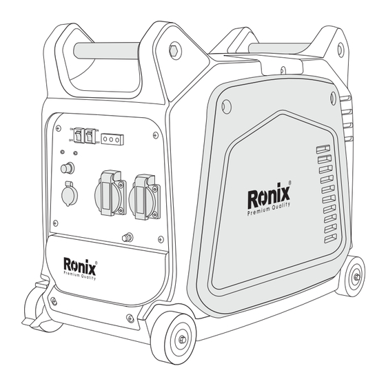
TECHNISCHE DATEN Modell RH-4794 Generatortyp Inverter-Generator Wechselspannung 220V/50Hz Maximale Leistung 2.6KW Nennleistung 2.3KW Leistungsfaktor Gleichstromausgang DC12V 5A USB-Anschluss 5V 3A Motormodell XY152F-3 Luftgekühlter, 4-Takt, OHV-Benzinmotor Bohrung x Hub mm×mm 57.8×52.4mm Hubraum 125cc Maximale Leistung 3.4KW / 5500U/min Kraftstoff Benzin Tankinhalt 7.5 Liters... - Page 4 GERÄTEKOMPONENTEN Tankdeckel Choke hebel Kraftstofffilter Tragegriff Seilzugstarter Zündkerze Kraftstofftank Schalldämpfer Kraftstoffhahn Wheel Überlastungsanzeige Brake Lever Kraftstoff Pumpe Öleinfülldeckel Ölwarnleuchte Luftfilter OVER ECON. ENGINE SW OUTPUT ALERT LOAD Wirtschaftssteuerung Schalter AC-PILOTLEUCHTE STOP USB _ Anschluss Engine Switch DC PROTECTOR DC_ Schutz AC 230V AC 230V ON/PUSH...
-
Page 5: Auspuffgase Sind Giftig
SICHERHEITSINFORMATIONEN AUSPUFFGASE SIND GIFTIG - Betreiben Sie den Motor niemals in geschlossenen Räumen, da dies zu Bewusstlosigkeit und Tod führen kann. Verwenden Sie den Motor in einem gut belüfteten Bereich. KRAFTSTOFF IST HOCHENTFLAMMBAR UND GIFTIG - Schalten Sie den Motor immer aus, bevor Sie Kraftstoff nachfüllen. - Tanken Sie niemals während des Rauchens oder in der Nähe offener Flammen. - Page 6 Cool Air ELEKTRISCHE SCHLAGGEFAHR - Betreiben Sie den Motor niemals bei Regen oder Schnee. - Berühren Sie das Gerät niemals mit nassen Händen, da sonst ein elektrischer Schlag auftreten kann. - Stellen Sie sicher, dass das Gerät geerdet ist. HINWEIS: Verwenden Sie ein Erdungskabel mit ausreichender Stromkapazität.
- Page 7 - Verbinden Sie den Generator nicht parallel mit einem anderen Gen- erator. ÖLWARNUNGSSYSTEM - Wenn der Ölstand unter das untere Niveau fällt, schaltet sich der Motor automatisch ab. Der Motor startet erst wieder, wenn Sie Öl nachfüllen. MOTORSCHALTER 1- EIN: Die Zündschaltung ist aktiviert. Der Motor kann gestartet werden. 2- STOPP: Die Zündschaltung ist deaktiviert.
- Page 8 Kraftstoffverbrauch und weniger Lärm. ECON.SW DC-SCHUTZSCHALTER Der DC-Schutzschalter schaltet sich automatisch aus, wenn die Last die bewertete Ausgangsleistung des Generators überschreitet. VORSICHT: - Reduzieren Sie die Last auf die spezifizierte bewertete Ausgangsleistung, wenn der DC-Schutzschalter auslöst. TANKDECKEL MIT LUFTENTLÜFTUNGSKNOPF Der Tankdeckel ist mit einem Luftentlüftungsknopf ausgestattet, um den Kraftstofffluss zu stoppen.
- Page 9 KRAFTSTOFFHAHN Der Kraftstoffhahn versorgt den Vergaser mit Kraftstoff. BREMSHEBEL Der Bremshebel verhindert das Bewegen des Generators. 1- Der Bremshebel funktioniert nicht, der Generator kann sich bewegen. 2- Der Bremshebel funktioniert, aber der Generator kann sich nicht bewegen. VOR BETRIEB DURCHZUFÜHRENDE PRÜFUNGEN HINWEIS: - Vor dem Betrieb sollten Sie jedes Mal Überprüfungen durchführen.
- Page 10 - Falls der Kraftstoff niedrig ist, füllen Sie mit bleifreiem Benzin nach. - Verwenden Sie das Kraftstofffiltersieb am Kraftstofffilterhals. - Empfohlener Kraftstoff: Bleifreies Benzin. - Tankinhalt Kapazität WARNUNG! - Füllen Sie den Tank nicht nach, während der Motor läuft oder heiß ist. - Schließen Sie den Kraftstoffhahn, bevor Sie Kraftstoff nachfüllen.
-
Page 11: Regelmässige Wartung
ÜBERPRÜFUNG DES MOTORÖLS Stellen Sie sicher, dass das Motoröl im oberen Bereich des Öleinfülllochs steht. Fügen Sie bei Bedarf Öl hinzu. - Entfernen Sie den Öleinfülldeckel und prüfen Sie den Ölstand. - Wenn der Ölstand unterhalb der unteren Markierung liegt, füllen Sie mit geeignetem Öl bis zur oberen Markierung auf. - Page 12 Teile Hinweise Überprüfen Sie den Zustand, stellen Sie den Abstand ein Zündkerze und reinigen Sie die Zündkerze. Ersetzen Sie sie bei Bedarf. Überprüfen Sie den Ölstand im Motor. Motoröl Ersetzen reinigen Sie das Ölfilter Ölfilter. Reinigen Sie den Luftfilter luftfilter.
-
Page 13: Fehlersuche
Überprüfen Sie auf Leckagen. Ziehen Sie die Dichtung nach oder ersetzen Sie sie bei Auspuffsystem Bedarf. Reinigen oder ersetzen Sie den Mufflersieb bei Bedarf. Überprüfen Sie den Vergaser Choke-Betrieb. Abkühlungssystem Check Fan Damage. Überprüfen Sie Startsystem den Betrieb des ... -
Page 14: Kraftstoff Ablassen
den Kraftstoffhahn auf “ON”. Verstopfter Kraftstoffleitungen Leitungen reinigen. Verstopfter Vergaser Vergaser säubern. 2- Moto öl system Unzureichender Ölstand Motoröl hinzufügen. 3- Elektrische Systeme Schlechter Funke: Verschmutzte oder defekte Zündkerze fehlerhaftes Zündsystem. Zündkerze ersetzen, Verbindungen sichern und korrekt einstellen. Unzureichende Kompression ... - Page 15 MOTOR 1- Zündkerze entfernen, etwa einen Esslöffel SAE 10W30 oder 20W40 Motoröl in das Zündkerzenloch gießen und die Zündkerze wieder einsetzen. 2- Den Motor mehrmals mit dem Seilzugstarter drehen (mit ausgeschalteter Zündung). 3- Den Seilzugstarter ziehen, bis Sie Kompression spüren. 4- Hör auf zu ziehen 5- Die äußere Oberfläche des Generators reinigen und einen Rostschutz auftragen.
- Page 16 GASOLINE INVERTER GENERATOR- 2.6KW RH-4794...
-
Page 17: Specifications
SPECIFICATIONS Model RH-4794 Type Inverter Generator AC Voltage 220V/50Hz Max. Output 2.6KW Rated Output 2.3KW Power Factor DC Output DC12V 5A USB Socket 5V 3A Model XY152F-3 Air-Cooled, 4 cycle, OHV, Gaso- Type line Engine Bore×Stroke mm×mm 57.8×52.4mm Displacement 125cc Max. -
Page 18: Parts List
PARTS LIST Fuel Tank Cap Carrying Handle Choke Lever Recoil Starter Fuel Spark Plug Fuel Tank Filter Muffler Fuel Wheel Cock Overload Brake Lever Fuel Oil Filler Indicator Light Pump Oil Warning Light Air Filter OVER ECON. ENGINE SW OUTPUT ALERT LOAD Economy Control Switch... -
Page 19: Safety Information
SAFETY INFORMATION EXHAUST FUMES ARE POISONOUS - Never operate the engine in a closed area or it may cause unconsciousness and death within a short time. Operate the engine in a well-ventilated area. FUEL IS HIGHLY FLAMMABLE AND POISONOUS - Always turn off the engine when refueling - Never refuel while smoking or in the vicinity of an open flame. -
Page 20: Electric Shock Prevention
Cool Air ELECTRIC SHOCK PREVENTION - Never operate the engine in rain or snow. - Never touch the machine with wet hands or an electrical shock will occur. - Be sure to ground (earth) the generator. NOTE: Use ground (earth) lead of sufficient current capacity. - Diameter: 0.12mm (0.005in)/ampere - EX: 10 Ampere --1.2mm (0.055in) CONNECTION NOTES... -
Page 21: Oil Warning System
OIL WARNING SYSTEM - When the oil level falls below the lower level, the engine stops automatically. Unless you refill with oil, the engine will not start again. ENGINE SWITCH The engine switch controls the ignition system. 1- ON The ignition circuit is switched on. The engine can be started. 2- STOP The ignition circuit is switched off. -
Page 22: Dc Circuit Protector
results are better fuel connection and less noise. ECON.SW DC CIRCUIT PROTECTOR The DC circuit protector turns off automatically when the load exceeds the generator-rated output. CAUTION: - Reduce the load to within the specified generator-rated output if the DC circuit protector turns off. FUEL TANK CAP AIR VENTKNOB The fuel tank cap is provided with an air vent knob to stop fuel flow. -
Page 23: Brake Lever
BRAKE LEVER The function of the brake lever is to prevent the generator from moving. 1- Brake lever is not working, the generator can move. 2- Brake lever is working, but the generator can’t move. PRE-OPERATION CHECK NOTE: - Pre-operation checks should be made each time the generator is used. CHECK ENGINE FUEL - Make sure there is sufficient fuel in the tank. -
Page 24: Check Engine Oil
WARNING! - Do not refill the tank while the engine is running or hot. - Close the fuel cock before refueling with fuel. - Be careful not to admit dust, dirt, water, or other foreign objects into fuel. - Do not fill above the top of the fuel filter or it may overflow when the fuel heats up later and expands. -
Page 25: Ground (Earth)
- Remove the oil filler cap and check the engine oil level. - If the oil level is below the lower level line, refill with suitable oil to the upper-level line. Do not screw in the oil filler cap when checking the oil level. - Change oil if contaminated. -
Page 26: Starting The Engine
OPEN STARTING THE ENGINE NOTE: - Before starting the engine, do not connect the electric apparatus. 1- Open the fuel tank air vent to the “OPEN” position. 2- Turn the fuel cock lever to the “ON” position. 3- Turn the engine switch to the “ON” position. ENGINE SWITCH STOP... - Page 27 4- When first time to use the generator sets, press the primer bulb 6 times after refueling the gasoline. 5- Turn the choke lever to the position. 6- Pull the starter handle slowly until resistance is felt. This is the “Compression” point.
-
Page 28: Using Electric Power
USING ELECTRIC POWER AC APPLICATION A- Check the AC pilot lamp for proper voltage. B- Turn off the switch(es) of the electrical appliance(s) before connecting to the generator. C- Insert the pulg(s) of the electrical appliance(s) into the receptacle. CHOKE CAUTION: - Be sure the electric apparatus is turned off before plugging it in. -
Page 29: Overload Indicator Light
OVERLOAD INDICATOR LIGHT The overload indicator light comes on when an overload of a connected electrical device is detected, the inverter unit overheats, or the AC output voltage rises. The electronic breaker will then activate, stopping power to the generator to protect the generator and any connected electric devices. The output pilot light (green) will flicker and the overload indicator light (red) will turn on, then the engine will stop running. - Page 30 A- Charging instructions for battery - Disconnect the leads for the battery. - Make the battery fluid filler cap loose fully. - Fill distilled water to the upper limit, if the battery fluid is low level. - Measure the specific gravity for the battery fluid by using the hydrometer, and calculate the charging time according to the table shown on the right side.
-
Page 31: Stopping The Engine
STOPPING THE ENGINE 1- Turn off the power switch of the electric apparatus or disconnect any electric devices. 2- Turn the engine switch to the “STOP” position. ENGINE SWITCH STOP 3- Turn the fuel cock lever to “OFF”. 4- Turn the fuel tank cap air vent knob counterclockwise to the “CLOSED” position. -
Page 32: Periodic Maintenance
CLOSED PERIODIC MAINTENANCE MAINTENANCE CHART - Regular maintenance is most important for the best performance and safe operation. Item Remarks Check The Condition, Adjust Spark The Gap, And Clean. Replace Plug If Necessary. Check Oil Level Engine Replace ... -
Page 33: Engine Oil Replacement
Valve Check And Adjust When The Engine Is Cold. Clearance Check The Fuel Hose For Cracks Or Damage. Replace If Fuel Line Necessary. Check For Leakage. Retighten Or Replace The Gasket If Necessary. Exhaust System Check Muffler Screen. ... - Page 34 3- Remove the oil filler cap 4- Place an oil pan under the engine. Tilt the generator to drain the oil completely 5- Replace the generator on a level surface. 6- Add engine oil to the upper level. 7- Install the oil filler cap. 8- Install the cover and tighten the screw - Recommended engine oil: 0.9L - API Service “...
-
Page 35: Air Filter
overfilling and damage to the engine - Clean the oil filter every other 100hr. AIR FILTER Maintaining an air cleaner in proper condition is very important. Dirt induced through improperly installed, improperly serviced, or inadequate elements damages and wears out engines. Keep the element always clean. - Remove the cover. - Page 36 CAUTION: The engine should never run without the element; excessive piston and/ or cylinder wear may result. CLEANING AND ADJUSTING SPARK PLUG 1- Remove the cover. 2- Check for discoloration and remove the carbon. 3- Check the spark plug type and gap. 4- Install the spark plug.
-
Page 37: Muffler Screen
WARNING! - Be sure the tank cap is tightened securely. MUFFLER SCREEN WARNING! - The engine and muffler will be very hot after the engine has been run. - Avoid touching the engine and muffler while they are still hot with any part of your body or clothing during inspection or repair. -
Page 38: Troubleshooting
3- Use the flathead screwdriver to pry the spark arrester out from the muffler 4- Remove the carbon deposits on the muffler screen and spark arrester using a wire brush. 5- Install the muffler screen. 6- Install the cover TROUBLESHOOTING ENGINE WON’T START 1- Fuel systems No fuel in tank... -
Page 39: Generator Won't Produce Power
Faulty ignition system Consult dealer. 4- Compression insufficient Worn out piston and cylinder Consult dealer. GENERATOR WON’T PRODUCE POWER Safety device (AC) to “OFF” Stop the engine, then restart. Safety device (DC) to “OFF” Press to reset the DC protector. ... - Page 40 www.ronixtools.com...
Need help?
Do you have a question about the RH-4794 and is the answer not in the manual?
Questions and answers