Table of Contents
Advertisement
Quick Links
Advertisement
Table of Contents

Related Manuals for Ronix RH-4790


Summary of Contents for Ronix RH-4790
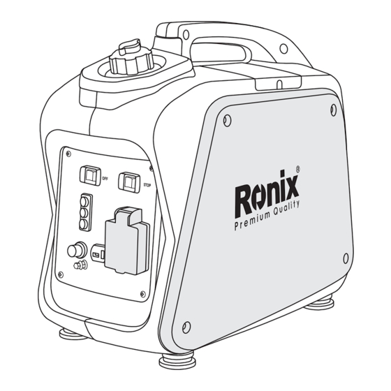
- Page 1 GASOLINE INVERTER GENERATOR 800W RH-4790...
-
Page 2: Specifications
SPECIFICATIONS Model RH-4790 Type Inverter Generator AC Voltage 220V / 50Hz Max. Output 0.80 KW Generator Rated Output 0.70 KW Power Factor DC Output DC12V 4A Model XY139F- 6 Air-cooled, 4 cycle, OHV, Type Gasoline Engine Bore×Stroke mm×mm 39×33.5 Displacement 40 cc Max. -
Page 3: Parts List
PARTS LIST 13 14 1- Economy control switch 2- Engine switch 3- Fuel tank 4- Spark plug GASOLINE INVERTER GENERATOR... -
Page 4: Work Area Safety
5- Muffler 6- Carrying handle 7- Choke lever 8- AC pilot light 9- Overload indicator light 10- Oil warning light 11- Ground (earth) terminal 12- DC protector 13- DC receptacle 14- AC receptacle 15- Fuel filter 16- Fuel tank cap 17- Fuel pump 18- Recoil starter 19- Fuel cock... -
Page 5: Engine And Muffler May Be Hot
- If you swallow any fuel, inhale fuel vapor, or allow any to get in your eyes, see your doctor immediately. If any fuel spills on your skin or clothing, immediately wash with soap and water and change your clothes. - When operating or transporting the machine, be sure it is kept upright. -
Page 6: Connection Notes
NOTE: Use ground (earth) lead of sufficient current capacity. - Diameter: 0.12mm (0.005 in)/ampere - EX: 10 Ampere -1.2mm (0.055 in) CONNECTION NOTES - Avoid connecting the generator to commercial power outlet. - Avoid connecting the generator in parallel with any other generator. CONTROL FUNCTION OIL WARNING SYSTEM - When the oil level falls below the lower level, the engine stops... -
Page 7: Economy Control Switch
ENGINE SWITCH The engine switch controls the ignition system. 1- ON (run) Ignition circuit is switched on. The engine can be started. 2- OFF (stop) Ignition circuit is switched off. The engine will not run. ENGINE SWITCH STOP ECONOMY CONTROL SWITCH When the economy control switch is turned “ON”, the economy control unit control the engine speed according to the connected load. -
Page 8: Fuel Tank Cap Air Ventknob
circuit protector turn off. DC PROTECTOR FUEL TANK CAP AIR VENTKNOB The fuel tank cap is provided with an air vent knob to stop fuel flow. The air vent knob must be turned once clockwise from the closed position. This will allow fuel to flow to the carburetor and the engine to run. When the engine is not in use, tighten the air vent knob counterclockwise until it is finger-tight to stop fuel flow. -
Page 9: Pre-Operation Check
PRE-OPERATION CHECK NOTE: - Pre-operation checks should be made each time the generator is used. CHECK ENGINE FUEL - Make sure there is sufficient fuel in the tank. - If fuel is low, refill with unleaded automotive gasoline. - Be sure to use the fuel filter screen on the fuel filter neck. - Recommended fuel: Unleaded gasoline. -
Page 10: Check Engine Oil
CHECK ENGINE OIL Make sure the engine oil is at the upper level of the oil filler hole. Add oil as necessary. - Remove oil filler cap and check the engine oil level. - If oil level is below the lower level line, refill with suitable oil to upper level line. -
Page 11: Starting The Engine
- Do not tilt the generator when adding engine oil. This could result in overfilling and damage to the engine STARTING THE ENGINE NOTE: - Before starting the engine, do not connect the electric apparatus. - Open the fuel tank air vent to the OPEN position. OPEN - Turn the fuel cock lever to the ON position. - Page 12 - Turn the engine switch to the ON position. ENGINE SWITCH STOP - When first time to use the generator sets, pressing the primer bulb 6 times after refuel gasoline - Turn the choke lever to the CHOKE position. Not necessary if ...
-
Page 13: Using Electric Power
- Pull the starter handle slowly until resistance is felt. This is the Compression point. Return the handle to its original position and pull swiftly. Do not fully pull out the rope. After starting, allow the starter handle to return to its original position while still holding the handle. Grasp the carrying handle firmly to prevent the generator from falling over when pulling the recoil starter. - Page 14 CAUTION: - Be sure the electric apparatus is turned off before plugging in. - Be sure the total load is within generator rated output. - Be sure the socket load current is within socket rated current. - The economy control switch must be turned to OFF when using electric devices that require a large starting current, such as a compressor or a submergible pump.
-
Page 15: Overload Indicator Light
OVERLOAD INDICATOR LIGHT The overload indicator light comes on when an overload of a connected electrical device is detected, the inverter unit overheats, or the AC output voltage rises. The electronic breaker will then activate, stopping power to the generation in order to protect the generator and any connected electric devices. - Page 16 CAUTION: - The generator AC output automatically resets when the engine is stopped and then restarted. - The overload indicator light may come on for a few seconds at first when using electric devices that require a large starting current, such as a compressor or a submergible pump.
-
Page 17: Stopping The Engine
Aim for Specific Gravity and Charging Time 1.30 1.26 1.22 1.18 1.14 1.10 1.06 Chargong Time Hr Battery Capacity 1. 30AH 20HR 2. 35AH 20HR 3. 47AH 20HR CAUTION: - Be sure the economy control switch is turned OFF while charging the battery. - Page 18 ECON SWITCH - Turn the fuel cock lever to OFF. - Turn the fuel tank cap air vent knob counterclockwise to the CLOSED position. CLOSE USER MANUAL...
-
Page 19: Periodic Maintenance
PERIODIC MAINTENANCE MAINTENANCE CHART - Regular maintenance is most important for the best performance and safe operation. Initial Every Every Every Pre- operation months months months months Item Remarks check (daily) 100Hr 300Hr 20 Hr 50Hr Check condition adjust gap and Spark ... - Page 20 Check for leakage. Retighten or replace gasket if Exhaust necessary System Check muffler screen. Clean / replace if necessary. Check choke Carburetor operation Cooling Check fan system damage. Starting Check recoil system starter operation. Check and adjust ...
-
Page 21: Engine Oil Replacement
ENGINE OIL REPLACEMENT - Place the machine on a level surface and warm up the engine for several minutes. Then stop the engine and turn the fuel cock knob to OFF. Turn the fuel tank cap air vent knob clockwise. - Loosen the screw and remove the cover. -
Page 22: Air Filter
- Replace the generator on a level surface. - Add engine oil to the upper level. - Install the oil filler cap - Install the cover and tighten the screw - Recommended engine oil: (see page 3) - API Service “ SJ” CAUTION: - Be sure no foreign material enters the crankcase. - Page 23 wet but not dripping. - Insert the element into the air filter. - Install the cover CAUTION: The engine should never run without the element; excessive piston and/ or cylinder wear may result. CLEANING AND ADJUSTING SPARK PLUG - Remove the cover. - Check for discoloration and remove the carbon.
- Page 24 - Standard electrode color: Tan Color - Standard Spark Plug: see page 3 - Spark Plug Gap: 0.6-0.7 mm (0.024-0.028 in) FUEL TANK FILTER - Remove the fuel tank cap and filter. - Clean the filter with solvent. If damaged, replace. - Wipe the filter and insert it.
-
Page 25: Muffler Screen
WARNING! - Be sure the tank cap is tightened securely. MUFFLER SCREEN WARNING! - The engine and muffler will be very hot after the engine has been run. - Avoid touching the engine and muffler while they are still hot with any part of your body or clothing during inspection or repair. -
Page 26: Generator Won't Produce Power
- Remove the carbon deposits on the muffler screen and spark arrester using a wire brush. - Install the muffler screen. - Install the cover TROUBLE SHOOTING ENGINE WON’T START FUEL SYSTEMS - No fuel supplied to combustion chamber. - No fuel in tank Supply fuel. -
Page 27: Drain The Fuel
STORAGE Long term storage of your machine will require some preventive procedures to guard against deterioration. DRAIN THE FUEL - Remove the fuel tank cap, drain the fuel from the fuel tank - Remove the cover, drain fuel from the carburetor by loosening the drain screw.
Need help?
Do you have a question about the RH-4790 and is the answer not in the manual?
Questions and answers
hi, I've bought a new portable gasoline generator of RONIX (RH- 4760) will you please describe me about proper type of oil for that and please send to me the instructions for changing the machine oil (After how many hours should the oil be changed?). Thanks for your attention
The recommended oil for the Ronix RH-4790 gasoline inverter generator is SAE 10W30. The oil should be changed if it becomes contaminated.
This answer is automatically generated