Table of Contents
Advertisement
Quick Links
Advertisement
Table of Contents

Related Manuals for Sonel WMGBMPI525


Summary of Contents for Sonel WMGBMPI525
- Page 3 USER MANUAL METER FOR ELECTRICAL INSTALLATION PARAMETERS MPI-525 SONEL S.A. Wokulskiego 11 58-100 Świdnica Poland Version 2.12 13.07.2023...
- Page 4 The MPI-525 meter is a modern, easy in use and safe measuring device. Please acquaint yourself with the present manual in order to avoid measuring errors and prevent possible problems related to opera- tion of the meter. MPI-525 – USER MANUAL...
-
Page 5: Table Of Contents
CONTENTS 1 Safety ........................ 5 2 Menu ........................6 2.1 Wireless transmission ....................6 2.2 Settings of measurements ..................6 2.2.1 Network voltage and frequency ..................7 2.2.2 Additional results in insulation resistance measurement ..........7 2.2.3 Main result of short circuit loop impedance measurement ..........8 2.2.4 Measurement settings .................... - Page 6 5.2 Data transmission with USB ................... 48 5.3 Data transmission with OR-1 radio module ............48 6 Power supply ....................50 6.1 Monitoring of the power supply voltage ..............50 6.2 Replacement of batteries (accumulators) ............... 50 6.3 Charging of accumulators ..................51 6.4 General principles regarding using Ni-MH accumulators ........
-
Page 7: Safety
1 Safety MPI-525 meter is designed for performing check tests of protection against electric shock in mains systems. The meter is used for making the measurements the results of which determine safety of electrical installations. Therefore, in order to provide conditions for correct operation and the correctness of the obtained results, the following recommendations must be observed: ... -
Page 8: Menu
2 Menu The Menu is accessible in each position of the rotary switch. Press MENU push-button. Select a proper item by means of push-buttons. Enter a selected op- tion by pressing ENTER. 2.1 Wireless transmission See chapter 5.3. 2.2 Settings of measurements Select a proper item by means of push-buttons. -
Page 9: Network Voltage And Frequency
2.2.1 Network voltage and frequency Before measurements a nominal network voltage U (110/190V, 115/200V, 127/220V, 220/380V, 230/400V or 240/415V) should be selected that is valid in the area where measurements are made. This voltage value is used for calculating the values of prospective short-circuit current. Determination of network frequency, that is the source of potential interferences, is necessary in order to select a proper measuring signal frequency in resistance-to-earth measurements. -
Page 10: Main Result Of Short Circuit Loop Impedance Measurement
2.2.3 Main result of short circuit loop impedance measurement By means of push-buttons se- lect main result in the form of imped- ance Z or prospective short-circuit current I ; confirm a choice made by means of ENTER push-button. 2.2.4 Measurement settings The setting enables activation/deactivation of the field displaying measurement settings. -
Page 11: Settings Of The Meter
By means of push-buttons se- lect the option of automatic incre- menting of field number after its stor- ing in the memory or the manual in- crementing option (automatic incre- menting is deactivated); confirm a choice made by means of ENTER push-button. -
Page 12: Lcd Backlight Time
2.3.2 LCD backlight time User can turn the LCD backlight on at any time by pushing button. The LCD backlight setting defines the period, after which the backlight is automatically turned off. When “Always” option is chosen, to turn the backlight off user will need to push button again. -
Page 13: Factory (Default) Settings
2.3.5 Factory (default) settings In order to introduce factory (default) settings, highlight YES by means of push-buttons and press ENTER push-button. 2.3.6 Program update ATTENTION! This function may be used only by the users who are fluent in operation of com- puter equipment. -
Page 14: Measurements
3 Measurements Remarks: - A progress bar is displayed during long measurements. - The content of this chapter should be thoroughly familiarized with since it describes the meter circuits, the methods of measurements and basic principles concerning interpretation of measurement results. - Result of the latest measurement is remembered by the meter until a next measurement is started or measurement settings are changed or the measuring function is changed by means of the rotary switch or the meter is switched off. -
Page 15: Measurement Of Short Circuit Loop Parameters
Remarks: WARNING: When phase voltage is detected on PE lead, measurements must be immediately stopped and a fault in the installation must be removed. - The person making a measurement must ensure that he/she is standing on a non-insulated floor during the measurement;... - Page 16 In order to select the voltage for calculating the prospective short circuit current I - nominal or measured - press F2 to select desired voltage and press ENTER. Connect test leads according to the drawing a) for measurement in L-N circuit or b) for measurement in L-L circuit The meter is ready for meas-...
- Page 17 Read out the re- sult. The result is displayed on the screen for 20s. The result can be recalled by pressing ENTER push-button. Remarks: - The result can be stored in the memory (see point 4.1). - When many measurements are made in short time intervals, the meter may emit a large amount of heat.
-
Page 18: Measurement Of Short Circuit Loop Parameters In L-Pe Circuit
3.3.2 Measurement of short circuit loop parameters in L-PE circuit Set the rotary switch of function se- lection at Z position. L-PE L-PE Press F1 push-button if L lead length needs to be selected. Select a lead length by means of push- buttons and press ENTER push-button. - Page 19 The meter is ready for meas- urement. Make measurement by pressing START push-button. Read out the re- sult. The result is displayed on the screen for 20s. The result can be recalled by pressing ENTER push-button. Remarks: - Double lead measurement is possible when a test lead other that the lead with a mains socket is selected.
-
Page 20: Measurement Of Short Circuit Loop Impedance In L-Pe Circuit Protected With Residual Current Device (Rcd)
3.3.3 Measurement of short circuit loop impedance in L-PE circuit protected with residual current device (RCD) Set the rotary switch of function se- lection at Z RCD position. L-PE Press F1 push-button if L lead length needs to be selected. Select a lead length by means of push-... -
Page 21: Prospective Short-Circuit Current
3.3.4 Prospective short-circuit current The meter always measures impedance Z . The short-circuit current is calculated according to the following formula: I where: Z - measured impedance, U - voltage that depends on settings of I button, according to the following Table: The selection in MENU... -
Page 22: Measurement Of Resistance-To-Earth
3.4 Measurement of resistance-to-earth The three-pole measuring method is the basic type of resistance-to-earth measurement. Disconnect earth elec- trode being tested from the installation of the building. Set the rotary switch of function selec- tion at R position. The current electrode (driven into earth) should be connected to H socket of the meter. The voltage electrode (driven into earth) should be connected to S socket of the meter. - Page 23 Press F1 push-button to change test voltage. Select test voltage by means of push-buttons and confirm by pressing ENTER. Press START push-button to start the measurement. Read out the result. Resistance of current electrode Resistance of voltage electrode Value of additional uncertainty caused by resistance of the elec- trodes Repeat the measurements (points 3, 7, 8) shifting the volt-...
- Page 24 Remarks: Measurement of resistance-to-earth may be carried out if voltage of interfer- ences does not exceed 24 V. Voltage of interferences is measured up to the level of 100 V but above 50 V it is signalled as dangerous. The meter must not be connected to voltages exceeding 100 V.
-
Page 25: Measurement Of Rcd Parameters
3.5 Measurement of RCD parameters Attention: Measurement of U is always conducted with the use of sinusoidal current 0.4I regardless n of the settings concerning waveform and multiplication factor I n 3.5.1 Measurement of RCD trip current Set the rotary switch of function selection at I position. - Page 26 Select an appropriate item by means of push- buttons and confirm by pressing ENTER. Connect the device to the installation according to the drawing. The meter is ready for measurement. Value of network volt- age and frequency can be read on the display. Press START to begin measurement.
-
Page 27: Measurement Of Rcd Trip Time
Remarks: - Measurement of t trip time for selective RCD is not available. Additional information displayed by the meter >U Touch voltage U exceeds a preset U threshold value. ! placed on the right side of the result means that RCD is out of order Lack of neutral lead that is necessary for I constant and... - Page 28 Press F1 push-button and move to selection of U Press F2 push-button and move to selection of RCD type. Press F3 push-button MODE and move to selection of measurement mode. Mark an appropriate position by means of push-buttons and confirm by pressing ENTER. Connect the device to the installation according to the drawing.
-
Page 29: Automatic Measurement Of Rcd Parameters
Read out the result. Remarks and information are the same as for I measurement. 3.5.3 Automatic measurement of RCD parameters The meter enables automatic measurement of the following: RCD trip times (t ), trip current (I touch voltage (U ) and resistance-to-earth (R ). - Page 30 Set the rotary switch of function selection at AUTO position. Press F1 push-button and move to I selection. n Press F2 push-button and move to selection of cur- rent waveform. Press F3 push-button and move to selection of RCD type.
- Page 31 Connect the device to the installation according to the drawing. The meter is ready for measure- ment. Value of network voltage and fre- quency can be read on the display. Press START push-button to start the measurement. If such measurements are selected that require triggering of RCD, operator of the meter should be in the vicinity of RCD and switch it on each time after it is tripped until the measure- ments are completed (a longer interruption may signify com-...
- Page 32 Read out the result. Groups of results displayed are changed by means of F3 and F4 push-buttons. Remarks: - The measurement is interrupted, if during measurement of U RCD has been tripped at 0.5I n current or if RCD has not been tripped in other cases or if a preset value of safe voltage U has been exceeded.
-
Page 33: Measurement Of Insulation Resistance
3.6 Measurement of insulation resistance WARNING: The object tested must not be live. Presence of any voltage across tested object is prohibited. 3.6.1 Double-lead measurement Set the rotary switch of function selection at R position. Press F1 push-but- ton and move to selection of nominal test voltage U Press F2 TIME... - Page 34 Connect test leads according to the drawing. Press and hold START push-but- ton. Measurement is performed continu- ously when the push-button is held in the pressed position. In order to maintain the measurement, press ENTER push- button while holding START push- button in the pressed position.
-
Page 35: Measurements With Autoiso-2500 Adapter
Remarks: During measurements of insulation resistance, dangerous voltage up to 2,5 kV present at the ends of test leads of MPI-525 meter. It is forbidden to disconnect test leads and to change the position of the function switch before completion of measurement. Failure to obey the above instruction will lead to high voltage electric shock and make it impossible to discharge the object tested. - Page 36 Press F1 push-button and move to selection of nominal test voltage U Press F2 TIME push-button and move to selection of a single measurement time. Press F3 MODE push-button and move to selection of lead or energetic cable type (3-, 4- or 5-cores lead).
- Page 37 View of the screen during measurement. Result of the present measurement is displayed in black. Read out the results. Additional results regarding to selected pair of cores (which main result is displayed in black) Selected pair of cores is changed by means of F1 and F2 push-buttons.
-
Page 38: Low-Voltage Measurement Of Resistance
3.7 Low-voltage measurement of resistance 3.7.1 Measurement of resistance of protective conductors and equipotential bonding with ±200 mA current Set the rotary switch of function selec- tion at R position. ±200 mA Press F1 push-button and move to selection of measurement mode. - Page 39 Connect the meter to the object tested. Measurement starts automatically. Read out the re- sults. Press START push-button in order to start a next measurement without dis- connecting test leads from the object. Remarks: ATTENTION! When “Object under voltage” message is displayed, the object tested is live. The measurement is blocked.
-
Page 40: Measurement Of Resistance
3.7.2 Measurement of resistance Set the rotary switch of function selec- tion at R position. ±200 mA Press F1 push-button and move to selection of measurement mode. Select R position by means of push-buttons and confirm by pressing ENTER. Connect the meter to the object tested. MPI-525 –... -
Page 41: Calibration Of Test Leads
Read out the result. Remarks: - Remarks and messages are the same as in point 3.8.1. 3.7.3 Calibration of test leads T eliminate the influence of the resistance of test leads on measurement result, the compensation (autozeroing) of resistance should be performed. For this purpose, R and R functions have ±200 mA... - Page 42 Follow the instructions displayed on the screen. AUTOZERO message appears that confirms completion of test leads calibration. To remove the AUTOZERO compensation (return to default cali- bration), perform the above-mentioned activities, but with test leads open in point 3. MPI-525 – USER MANUAL...
-
Page 43: Checking Sequence Of Phases
3.8 Checking sequence of phases Set the rotary switch of function selection position. Connect the meter to the installation according to the drawing. Phase-to-phase voltages. The arrow rotates clockwise: correct Signalling the sequence of presence of phases; individual phases. the arrow rotates counterclockwise: incorrect sequence of phases. -
Page 44: Memory Of Measurement Result Data
Memory of measurement result data MPI-525 meters are equipped with the memory that can store 50,000 single measurement results. The whole memory is divided into 10 memory banks containing 99 memory cells each. Thanks to dy- namic memory allocation, each of the memory cells can contain different quantity of single measurement results, depending on the needs. - Page 45 The cell is occupied for a given type of measurement. Measurement (memory cell) is selected by means of push-buttons; memory bank is selected by means of push- buttons . Storing of data in the memory is performed by means of ENTER push-button.
-
Page 46: Viewing Memory Data
4.2 Viewing memory data Set the rotary switch of function selection at MEM position. Select “Memory browsing” by means push-buttons. Press ENTER push-button. First of the four results stored in this cell. Select memory bank by means of push-buttons; se- lect a memory cell by means of push-buttons;... - Page 47 Main result Supplementary results or Z L-PE RCD or I L-PE L-PE at 0.5I , sinusoidal current, positive and nega- n tive initial phase at 1I , sinusoidal current, positive and negative n initial phase at 2I , sinusoidal current, positive and negative n initial phase at 5I...
-
Page 48: Deleting Memory Data
Main result Supplementary results CABLE 5: R (N-PE), , [LIMIT I], [NOISE] (L1-PE), , [LIMIT I], [NOISE] (L1-N), , [LIMIT I], [NOISE] CABLE 5: R (L2-N), , [LIMIT I], [NOISE] (L3-N), , [LIMIT I], [NOISE] (L1-L2), , [LIMIT I], [NOISE] CABLE 5: R (L1-L3), , [LIMIT I], [NOISE]... - Page 49 Press ENTER push-button. Select deletion of the whole memory, a memory bank or a measurement by means push-buttons. Follow the instruction displayed by the meter. MPI-525 – USER MANUAL...
-
Page 50: Data Transmission
USB cable and appropriate software. If the required accessories such have not been purchased along with the meter, then they are available from the manufacturer or an authorised distributor. The accessories may be used with many devices manufactured by SONEL S.A. equipped with the USB interface. - Page 51 4. If a PIN code change is necessary, select Modify PIN code. 5. Set the required code with the cursors. The same code must be entered in the computer programme. It is used for securing transmission. 6. To start transmission, select Wireless transmission in the MENU or press F1 in the MEM position. The following messages will be displayed: Connecting and then Connection active.
-
Page 52: Power Supply
6.2 Replacement of batteries (accumulators) MPI-525 meter is powered by 4 batteries (LR14). It can be also powered by the manufacturer’s accumulator package (SONEL NiMH). Battery charger is installed inside the meter and cooperates only with the manufacturer’s accumu- lator package. The charger is powered by external power supply adapter. It can be also powered from the car cigarette lighter socket. -
Page 53: Charging Of Accumulators
Replace the accumulators, Replace the four screws of the accumulators/batteries compartment. NOTE! Do not use the meter when the accumulator compartment is removed or open nor power it from other sources than mentioned in this manual. 6.3 Charging of accumulators Charging commences once the power supply has been connected to the meter regardless of the fact whether the meter is on or off. -
Page 54: General Principles Regarding Using Ni-Mh Accumulators
Note: - As a result of interferences in the network it is possible that the process of charging of accumulators will finish too fast. In the case too short a time of charging is detected it is necessary to remove the plug of the charger and start charging anew. -
Page 55: Cleaning And Maintenance
- Modern fast chargers detect both too low and too high a temperature of accumulators and react to the situation adequately. Too low a temperature should prevent the start of the process of charging, which might damage the accumulator irreparably. An increase of the temperature of the accumulator is a signal to stop charging and is a typical phenomenon. -
Page 56: Technical Data
10 Technical data 10.1 Basic data abbreviation „m.v.” used in the specification of accuracy signifies standard measured value Measurement of alternating voltages (True RMS) Range Resolution Accuracy (2% m.v. + 6 digits) 0.0...299.9 V 0.1 V (2% m.v. + 2 digits) 300…500 V ... - Page 57 Indications of short-circuit current I Test ranges according to IEC 61557 can be calculated on the basis of test ranges for Z and nominal voltages. Display range Resolution Accuracy 0.055…1.999 A 0.001 A 2.00...19.99 A 0.01 A 20.0...199.9 A 0.1 A Calculated on the basis of accuracy for fault loop 200...1999 A...
- Page 58 Measurement of parameters of RCD Nominal working voltage U : 110 V, 115 V, 127 V, 220 V, 230 V, 240 V Working range of voltage: 95…270 V Nominal network frequency f : 50 Hz, 60 Hz ...
- Page 59 Measurement of resistance-to-earth R Selected nom- Test inal current of Test range Resolution Accuracy current 0..+10% m.v. ±8 digits 10 mA 0.01 k...5.00 k 4 mA 0.01 k 0..+10% m.v. ±5 digits 30 mA 12 mA 0.01 k...1.66 k 1 ..500 100 mA 40 mA 1 ..166 ...
- Page 60 Measurement of RCD trip current I for residual direct current Test range according to IEC 61557: (0.2...2)I n Selected nomi- nal current of Test range Resolution Test current Accuracy 10 mA 2.0..20.0 mA 0.1 mA 30 mA 6..60 mA 10 % I 100 mA 20..200 mA 0.2 x I...
- Page 61 Measurement of resistance with low current Range Resolution Accuracy 0.0...199.9 0.1 (3% m.v. + 3 digits) 200...1999 1 Voltage at open terminals: 4…9 V Output current < 8 mA Audio signal for resistance being measured < 30 ±50% ...
-
Page 62: Other Technical Data
EN 60529................ IP54 d) power supply of the meter..........................alkaline batteries 4x1,5 V LR14 (C) or accumulator package SONEL NiMH 4,8 V 4,2 Ah e) parameters of AC adapter for the battery charge ......100 V…240 V, 50 Hz…60 Hz dimensions ....................... -
Page 63: Additional Data
10.3 Additional data Data on additional uncertainties are useful mainly when the meter is used in non-standard condi- tions and for metrological laboratories for the purpose of calibration. 10.3.1 Additional uncertainties according to IEC 61557-2 (R Significant parameter Designation Additional uncertainty Position Supply voltage 0% (BAT is not lit) -
Page 64: Additional Uncertainties According To Iec 61557-6 (Rcd)
Additional uncertainty caused by serial interference voltage Additional uncertainty [Ω] 0.00...9.99 Ω ±((0.01R + 0.012)U + 0.003 U 10.0...99.9 Ω ±((0.001R + 0.05)U + 0.001 U 100 Ω...1.99 kΩ ±((0.001R + 0.5)U + 0.001 U Additional uncertainty caused by resistance of electrodes: ... -
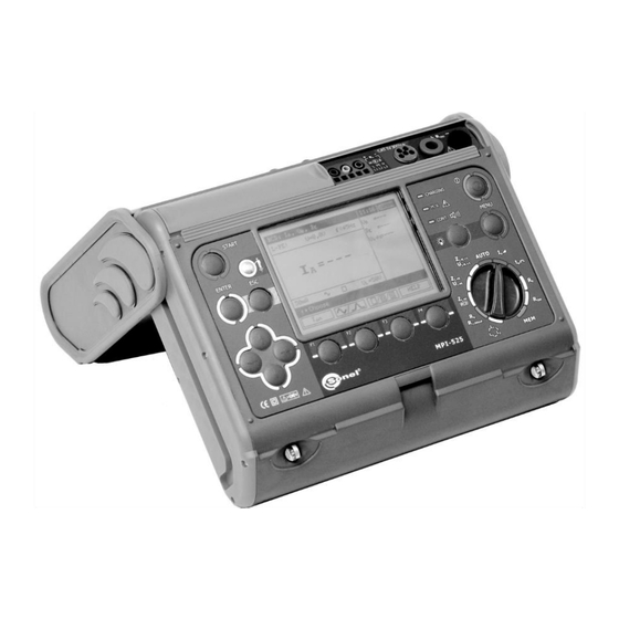
Page 65: Positions Of The Meter's Cover
3 – Cover in the position that enables convenient use of the meter suspended on the neck by means of hanging straps 12 Manufacturer The manufacturer of the device, which also provides guarantee and post-guarantee service is the following company: SONEL S.A. Wokulskiego 11 58-100 Świdnica Poland tel. +48 74 884 10 53 (Customer Service) e-mail: customerservice@sonel.com... - Page 66 NOTES MPI-525 – USER MANUAL...
- Page 68 MPI-525 – USER MANUAL...
Need help?
Do you have a question about the WMGBMPI525 and is the answer not in the manual?
Questions and answers