Table of Contents
Advertisement
Quick Links
Advertisement
Table of Contents

Related Manuals for Sonel MRU-11


Summary of Contents for Sonel MRU-11
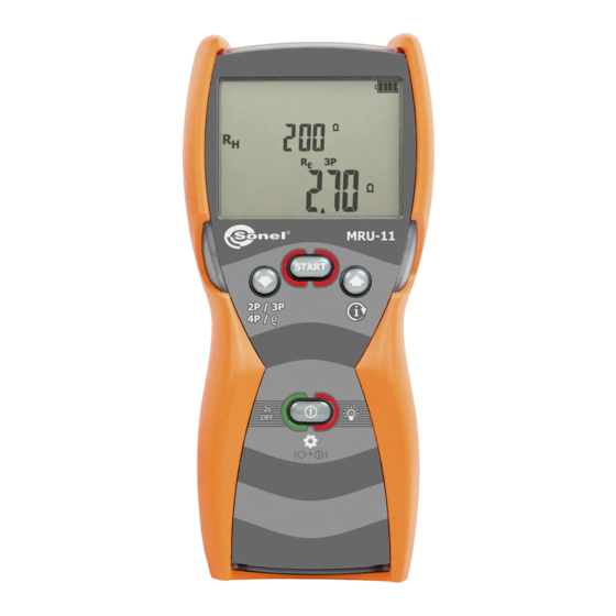
- Page 3 USER MANUAL EARTH RESISTANCE METER MRU-11 SONEL S.A. Wokulskiego 11 58-100 Świdnica Version 1.05 22.07.2021...
- Page 4 The MRU-11 meter is a modern, easy and safe measuring device. Please acquaint yourself with this manual in order to avoid measuring errors and prevent possible problems in operation of the meter. MRU-11 – USER MANUAL...
-
Page 5: Table Of Contents
3P, R 9.2.3 Additional uncertainties according to IEC 61557-5 (R 3P) ............ 28 10 Accessories ....................29 10.1 Standard accessories .................... 29 10.2 Optional accessories ....................30 11 Manufacturer ....................31 12 Laboratory services ..................32 MRU-11 – USER MANUAL... -
Page 6: Safety
MRU-11 meter is designed to measure earth resistance values. Any application that differs from those specified in the present manual may result in a damage to the device and constitute a source of danger for the user. -
Page 7: Turning The Meter On And Activating Screen Backlight
ON and then OFF the screen backlight; To turn OFF the device, press and hold ON/OFF button for approx. 2 sec- onds. A screen indicating shut- ting off the device is shown briefly. MRU-11 – USER MANUAL... -
Page 8: Meter Configuration
Short press START button to accept the selected value. You will enter the screen with settings of audio messages - bEEP. Use UP and DOWN buttons to turn the audio messages ON ( ) or OFF ( MRU-11 – USER MANUAL... - Page 9 You will enter the screen with measuring voltage selection Un. Use UP and DOWN buttons to set the measuring voltage at 25 V or 50 V. The measuring voltage set relates to all measurement functions in the meter. MRU-11 – USER MANUAL...
- Page 10 Long press (> 2 s) ON/OFF button to turn off the meter without accepting the changes introduced at the current setting position. Short press (> 2 s) ON/OFF button to enter the measurement screen R 3P without accepting the changes introduced at the current setting position. MRU-11 – USER MANUAL...
-
Page 11: Measurements
24 V but lower than 40 V, the xxV!, >24V, NOISE! and measurement is blocked. The interference voltage is lower than 24 V, but with a high NOISE! value - the measurement result may be affected by addi- tional uncertainty. MRU-11 – USER MANUAL... -
Page 12: Measurement Of Earth Resistances With 3-Pole Method (R 3P)
→ meter → H current electrode → earth → tested earth electrode; • S electrode (voltage electrode) for measuring the voltage drop across the resistance of the meas- ured earthing as a result of current flow. Disconnect the tested earth electrode from the installation of the facility. MRU-11 – USER MANUAL... - Page 13 The earth electrode being tested and the current electrode and the voltage electrode should be located in one line. Press START. The progress of the measurement is indi- cated by horizontal lines on the screen. MRU-11 – USER MANUAL...
- Page 14 24 V. Voltage of interferences is measured up to the level of 100 V, but above 40 V it is signalled as dangerous. The meter must not be connected to voltages exceeding 100 V. MRU-11 – USER MANUAL...
- Page 15 Flashing edges of symbols: E or H or S, two or all three at Flashing edges the same time: disconnected one, two or three leads to the terminals, or the resistance of the auxiliary auxiliary elec- trode/s is outside the measuring range. MRU-11 – USER MANUAL...
-
Page 16: Measurement Of Earth Resistances With 4-Lead Method (R 4P)
Press DOWN button until the screen of R measurement appears. The meter is in the mode of measuring the in- terference voltage between the test terminals. The measuring voltage is compatible with the voltage selected when setting up the device. MRU-11 – USER MANUAL... - Page 17 R whereas the upper part of the screen shows additional results for R . The re- sult is displayed for 20 seconds. The result can be recalled by pressing UP button. MRU-11 – USER MANUAL...
- Page 18 In majority of cases the achieved measurement ac- curacy is satisfactory. However, you should always be aware of the uncertainty in- cluded in the measurement. MRU-11 – USER MANUAL...
- Page 19 Ω value Flashing symbols: Flashing symbols E or H or S, or both of them, or all three at the same time, one or two or three test leads are dis- connected from the measurement sockets. MRU-11 – USER MANUAL...
-
Page 20: Measurement Of Earth Resistances With 2-Pole Method (R 2P)
Test leads should be connected to the measurement terminals in the device, as shown above. In order to start the measurement, press START button. MRU-11 – USER MANUAL... - Page 21 24 V but lower than 40 V, the NOISE! and measurement is blocked. The interfering signal (noise signal) is below 24 V, but with NOISE! a high value - the measurement result may be affected by additional uncertainty. MRU-11 – USER MANUAL...
-
Page 22: Soil Resistivity Measurement (Ρ)
Connect the current electrode driven into ground to the E socket of the meter. Turn on the meter using ON/OFF but- ton. Set measurement unit and distance L between electrodes according to sec. 3 … steps Press DOWN button until the screen of ρ measurement appears. MRU-11 – USER MANUAL... - Page 23 (the Wenner’s method). If this is not the case the earthing resistance measurement must be carried out by means of the four-pole method and calculations must be performed individually. Pay particular attention to the quality of the connection of the tested object with the MRU-11 – USER MANUAL...
- Page 24 Flashing symbols E or ES or H or S, or two of them, or Flashing symbols: three, or all of them at the same time – one or two or three or four test leads are disconnected from the measurement sockets. MRU-11 – USER MANUAL...
-
Page 25: Power Supply
Message bAtt indicates that batter- ies/rechargeable batter- ies are totally discharged, all measurements are blocked. The meter switches off automatically after 5 sec. MRU-11 – USER MANUAL... -
Page 26: Replacing (Rechargeable) Batteries
5.2 Replacing (rechargeable) batteries MRU-11 is powered by four AA alkaline LR6 batteries or rechargeable batteries of NiMH type. The (rechargeable) batteries are placed in the compartment at the bottom of the enclosure. The de- vice is not equipped with an internal battery charger. Rechargeable batteries must be recharged in an external charger. -
Page 27: General Principles Regarding Using Ni-Mh Rechargeable Batteries
If meter is to be stored for a prolonged period of time, the batteries must be removed from the device. In order to prevent a total discharge of the battery pack in the case of a prolonged storage, charge it from time to time. MRU-11 – USER MANUAL... -
Page 28: Dismantling And Disposal
Measuring current at the short circuit of > 20 mA. Measuring frequency of 125 Hz or 150 Hz. Selected test voltage: 25 V or 50 V. Maximum interference voltage for the R measurement is 24 V. MRU-11 – USER MANUAL... - Page 29 (above sea level) ....................≤2000 m* x) quality standard ..........design and manufacturing are ISO 9001 compliant y) measurement method ............technical, conforming to EN 61557-5 z) the device meets the EMC requirements according to: ....EN 61326-1 and EN 61326-2-2 MRU-11 – USER MANUAL...
-
Page 30: Additional Data
±0.2 digit/°C for R<1 kΩ Temperature ±0.07%/°C ±0.2 digit/°C for R≥1 kΩ According to the formulas shown Serial interference voltage in par. 9.2.1 (U =3V 50/60Hz) Resistance of earth contact According to the formula in probes par. 9.2.2 MRU-11 – USER MANUAL... -
Page 31: Accessories
1 pc. WAFUTM6 1 pc. Harness for the device (type M-1) WAPOZSZE4 M1 hanging hook straps WAPOZUCH1 1 pc. AA battery LR6 4 pcs. User manual 1 pc. Calibration certificate issued by an accredited laboratory 1 pc. MRU-11 – USER MANUAL... -
Page 32: Optional Accessories
Cable on the reel, 50 m, yellow, for measuring earthing values WAPRZ050YEBBSZ (banana plugs) Cable on the reel, 100 m, red, for measuring WAPRZ100REBBSZ earthing values Cable on the reel, 200 m, yellow, for measur- WAPRZ200YEBBSZ ing earthing values MRU-11 – USER MANUAL... -
Page 33: Manufacturer
The manufacturer of the device and provider of guarantee and post-guarantee service: SONEL S.A. Wokulskiego 11 58-100 Świdnica Poland tel. +48 74 858 38 60 fax +48 74 858 38 09 E-mail: export@sonel.pl Web page: www.sonel.pl NOTE! Service repairs must be performed only by the manufacturer. MRU-11 – USER MANUAL... -
Page 34: Laboratory Services
National Metrological Institute. According to ILAC-G24 „Guidelines for determination of calibration intervals of measuring instru- ments”, SONEL S.A. recommends periodical metrological inspection of the instruments it manufac- tures no less frequently than once every 12 months.
Need help?
Do you have a question about the MRU-11 and is the answer not in the manual?
Questions and answers