Table of Contents
Advertisement
Quick Links
Advertisement
Table of Contents

Subscribe to Our Youtube Channel
Related Manuals for Sonel MIC-2511


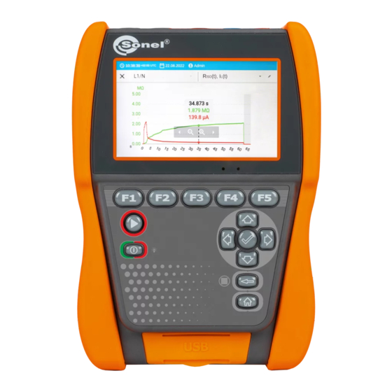
Summary of Contents for Sonel MIC-2511
- Page 3 User manual MIC-2511 Insulation resistance meter SONEL S.A. Wokulskiego 11 58-100 Świdnica Poland Version 1.00 07.10.2022...
- Page 4 The MIC-2511 meter is a modern, top quality measuring instrument which is easy and safe to use, provided that the principles presented in this manual are observed. In addition, becoming acquainted with the manual will help you avoid measuring errors and will prevent any possible problems with the operation of the meter.
-
Page 5: Table Of Contents
Correcting the R value to the reference temperature ................ 44 5.2.1 Correction without the temperature probe ......................44 5.2.2 Correction with the temperature probe ....................... 45 6 Memory of the meter.........................47 Memory structure and management ..................... 47 MIC-2511 │ USER MANUAL... - Page 6 14.3 Additional data ............................60 14.3.1 Additional uncertainties according to EN IEC 61557-2 (R ) ................60 15 Accessories ..........................61 15.1 Standard accessories ..........................61 15.2 Optional accessories ..........................62 16 Manufacturer ..........................62 17 Laboratory services ........................63 MIC-2511 │ USER MANUAL...
-
Page 7: General Information
CAT III – concerns measurements performed in buildings installations, CAT IV – concerns measurements performed at the source of low voltage installation. Behaviour of signalling LEDs The LED is on The LED flashes The LED flashes slowly continuously rapidly MIC-2511 │ USER MANUAL... -
Page 8: Safety
Safety The MIC-2511 meter is designed for performing inspection tests for protection against electric shock in mains systems. The meter is used for making measurements and providing results to deter- mine safety of electrical installations. Therefore, in order to provide the conditions for correct operation and accuracy of obtained results, the following recommendations must be observed: ... -
Page 9: Quick Start
You can save measurements in two ways: by performing a measurement and then assigning it to an object in the memory structure, entering an object in the memory structure and making a measurement at this memory location. MIC-2511 │ USER MANUAL... -
Page 10: Interface And Configuration
Add a measurement object Finish the measurement Measurement settings and limits Repeat the measurement Show the graph Memory Add an object Search Add a folder Go to the parent folder Add an instrument Add a measurement MIC-2511 │ USER MANUAL... -
Page 11: Gestures
To activate a given interface element, use the arrows to select it (successive selected elements will be highlighted), and then press the button to confirm your selection. The same principle ap- plies to the entire interface: from measurement screens, through the memory management menu and to the help. MIC-2511 │ USER MANUAL... -
Page 12: User's Account
The meter can have only one administrator (admin) and a maximum of 4 users with limited rights. The user created by the administrator receives their own meter settings. These settings can only be changed by that user and the administrator. MIC-2511 │ USER MANUAL... -
Page 13: Adding And Editing Users
(sec. 3.6.3). 3.5.3 Switching users To change the user, log out the current user and confirm the ending of the session. Now you can log in as another user. MIC-2511 │ USER MANUAL... -
Page 14: Configuration Of The Meter - Main Settings
ID auto increment – creating new memory items with a unique ID for the parent folder in sequential numbering. Name auto increment – creating new memory items according to previ- ously selected names and types. MIC-2511 │ USER MANUAL... -
Page 15: Information
Before starting the deletion, we recommend that you transfer the data to a USB stick or a computer. Factory reset of the meter. All saved folders, measurements, user accounts and entered settings will be deleted. After selecting the desired option, confirm your decision and follow the prompts. MIC-2511 │ USER MANUAL... -
Page 16: Measurements
The current limitation occurs in the first phase of the measurement due to charging the capacitance of the tested object. Graph 4.1. The actual test voltage U as a function of the measured insulation resistance R (for maximum test voltage) MIC-2511 │ USER MANUAL... -
Page 17: Before You Start
In case of power cables measure the insulation resistance between each conductor and other conductors shorted and grounded (Fig. 4.1, Fig. 4.2). In shielded cables, the shield is also shorted. Fig. 4.1. Measurement of an unshielded cable Fig. 4.2. Measurement of a shielded cable MIC-2511 │ USER MANUAL... - Page 18 G socket of the meter should be connected to the sec- ond winding, and R + socket to the ground potential. - – shielded test lead MIC-2511 │ USER MANUAL...
-
Page 19: Rcont Measurements
G socket of the meter is connected with the insulators of disconnector terminals. - – shielded test lead 4.1.2 Connections for R measurements CONT Low-voltage measurement of resistance is carried out in the following circuit. MIC-2511 │ USER MANUAL... -
Page 20: Connections For Epa Measurements
4.1.3 Connections for EPA measurements The connection layouts vary depending on what you want to measure. 4.1.3.1 Point-to-point resistance – R P1-P2 MIC-2511 │ USER MANUAL... - Page 21 4.1.3.2 Point-to-ground resistance – R MIC-2511 │ USER MANUAL...
- Page 22 4.1.3.3 Surface resistance – R MIC-2511 │ USER MANUAL...
- Page 23 4.1.3.4 Volume resistance – R MIC-2511 │ USER MANUAL...
-
Page 24: Measurement Indicators
The meter is measuring the insulation Continuity is maintained. resistance. ▼ The meter has finished measuring the insulation resistance and is currently dis- charging the tested object. ▼ The measurement is completed and the tested object is discharged. MIC-2511 │ USER MANUAL... -
Page 25: Measurement Settings
T If you have set limits, the meter will show if the result are within them. – the result is within the set limit. – the result is outside the set limit. – assessment not possible. MIC-2511 │ USER MANUAL... -
Page 26: Visual Test
The test summary screen will appear. Touching the bar with the result will reveal your selec- tions from step 2. If you want to enter additional information about the study, expand the Attachments field and fill in the comment field. MIC-2511 │ USER MANUAL... -
Page 27: Insulation Resistance - Riso
Testing will continue until it reaches the preset time (sec. 4.1.5) or until is pressed. Touching the bar with the result reveals partial results. During the measurement, it is possible to display the graph (sec. 5.1). MIC-2511 │ USER MANUAL... - Page 28 SAVE TO THE PREVIOUS ONE – save the result in the folder/device ► where the result of the previously performed measurement was saved. MIC-2511 │ USER MANUAL...
- Page 29 R + and R message DISCHARGING is displayed, as well as the value of U voltage that is present at that time on the object. U decreases over time until it is fully discharged. MIC-2511 │ USER MANUAL...
-
Page 30: Measurements Using The Autoiso-2511 Adapter
In order to shorten the measurement time and eliminate the inevitable connection errors, Sonel recommends an adapter that switches between individual pairs of conductors for the operator. - Page 31 The screen displays the label of the connected adapter and the icon for selecting the number of wires of the tested object. Determine the number of wires of the tested object. For each pair of conductors enter the measurement settings (sec. 4.1.5). Connect the adapter to the tested object. MIC-2511 │ USER MANUAL...
- Page 32 SAVE TO THE PREVIOUS ONE – save the result in the folder/device ► where the result of the previously performed measurement was saved. Remarks as for R measurement. MIC-2511 │ USER MANUAL...
-
Page 33: Measurements With A Voltage Increasing In Steps - Sv
Testing will continue until it reaches the time preset by the user (sec. 4.1.5) or until is pressed. Touching the bar with the result reveals partial results. During the measurement, it is possible to display the graph (sec. 5.1). MIC-2511 │ USER MANUAL... - Page 34 SAVE TO THE PREVIOUS ONE – save the result in the folder/device ► where the result of the previously performed measurement was saved. Remarks as for R measurement. MIC-2511 │ USER MANUAL...
-
Page 35: Measurement With Ramp Test - Ramptest
(a breakdown of the tested object occurs), the measurement is stopped and the meter displays the voltage at which it occurred. Select RampTest measurement. Enter the measurement settings (sec. 4.1.5). Connect test leads according to sec. 4.1.1. MIC-2511 │ USER MANUAL... - Page 36 SAVE AND ADD – create a new folder/device which is equivalent to the ► folder/device where the result of the previously performed measurement was saved, SAVE TO THE PREVIOUS ONE – save the result in the folder/device ► where the result of the previously performed measurement was saved. MIC-2511 │ USER MANUAL...
-
Page 37: Dielectric Discharge Indicator - Dd
U duration of the measurement t, limits (if necessary). The meter will suggest possible settings. Select DD measurement. Enter the measurement settings (sec. 4.1.5). Connect test leads according to sec. 4.1.1. MIC-2511 │ USER MANUAL... - Page 38 SAVE TO THE PREVIOUS ONE – save the result in the folder/device ► where the result of the previously performed measurement was saved. In environments with strong electromagnetic interferences the measurement may be affected by an additional error. MIC-2511 │ USER MANUAL...
-
Page 39: Low-Voltage Measurement Of Resistance - R
To disable compensation of the resistance of leads, repeat step 2 with open test leads. Then the measurement result will contain the resistance of test leads. 4.7.2 Measurement of resistance (R Select R measurement. Connect test leads. Measurement starts automatically and lasts continuously. ▼ ∞ MIC-2511 │ USER MANUAL... -
Page 40: Measurement Of Resistance Of Protective Conductors And Equipotential Bonding With ±200 Ma Current
The result is the arithmetic mean of the values of two measurements at a current of 200 mA with opposite polarities: R and R CONT+ CONT- CONT CONT MIC-2511 │ USER MANUAL... - Page 41 SAVE TO THE PREVIOUS ONE – save the result in the folder/device ► where the result of the previously performed measurement was saved. MIC-2511 │ USER MANUAL...
-
Page 42: Measurements In The Epas
100 kΩ ≤ R <100 GΩ Insulating packaging ≥ 100 GΩ Detailed guidelines can be found in the standards: IEC 61340-5-1, IEC/TR 61340-5-2, ANSI/ ESD S20.20, ANSI/ESD S541 and in the standards referred to in the above-mentioned documents. MIC-2511 │ USER MANUAL... - Page 43 SAVE TO THE PREVIOUS ONE – save the result in the folder/device ► where the result of the previously performed measurement was saved. MIC-2511 │ USER MANUAL...
-
Page 44: Special Features
During the measurement, it is possible to display the graph. Using the options on the top bar, you can display: a graph for the required pair of wires, ▼ the data set to be presented. You can also open the graph after the measurement is finished. ▼ MIC-2511 │ USER MANUAL... - Page 45 Switching to the shortened graph (last 5 seconds of the measurement) Fitting the entire graph on the screen ◄► Scrolling the graph horizontally Extending the graph horizontally Narrowing the graph horizontally Return to the measurement screen MIC-2511 │ USER MANUAL...
-
Page 46: Correcting The R Iso Value To The Reference Temperature
20°C (R ) and 40°C (R ISO k20 ISO k40 To obtain a temperature reading, you can also connect a temperature probe to the meter and enter its reading. See sec. 5.2.2, step 1. MIC-2511 │ USER MANUAL... -
Page 47: Correction With The Temperature Probe
Connect the temperature probe to the meter. The temperature measured by the instrument is displayed at the top of the screen. Perform the measurement. Save the result in the memory Go to this result in the memory of the meter. └ MIC-2511 │ USER MANUAL... - Page 48 The meter will convert the measured resistance into the resistance at the reference temperature: 20°C (R ) and ISO k20 40°C (R ISO k40 MIC-2511 │ USER MANUAL...
-
Page 49: Memory Of The Meter
Search function To find the desired folder or object faster, use the search function. After selecting icon , simply enter the name of what you are looking for and tap on the appropriate result to proceed. ▼ MIC-2511 │ USER MANUAL... -
Page 50: Saving Measurement Result Data To The Memory
From the object in memory to the measurement result In the meter’s memory, go to the location where the results are to be saved. └ ▼ Select the measurement you want to perform ▼ Perform the measurement. Save the result in the memory. MIC-2511 │ USER MANUAL... -
Page 51: Data Transmission
Sonel Reports PLUS. The software may be used for many devices manufactured by SONEL S.A. which are equipped with a USB interface. Detailed information is available from the manufacturer and distributors. If the required software has not been purchased with the meter, it may be obtained from the manu- facturer or from an authorised distributor. -
Page 52: Software Update
8 Software update Download the update file from the manufacturer's website (www.sonel.com). Save the update file to a USB stick. The stick must be formatted as a FAT32 file system. Turn the meter off. Insert the USB stick into the right port of the meter. -
Page 53: Troubleshooting
Reset the meter to the factory settings (sec. 3.6.6). the menu, long saving to memory, etc. Contact the customer service centre and provide the error FATAL ERROR message and error code. code to get help. MIC-2511 │ USER MANUAL... -
Page 54: Power Supply
Battery failure. It is recommended to replace Battery status unknown. Contact the customer it with a new one. service centre. Additional information displayed by the meter Low battery charge level. Battery problem Charging of the battery is in progress. MIC-2511 │ USER MANUAL... -
Page 55: Battery Power
It is possible to charge the battery when carrying out the measurements. To do this, just connect the factory supplied charger to the meter. When the meter is turned off by button or by AUTO-OFF, the charging process is not stopped. MIC-2511 │ USER MANUAL... -
Page 56: General Rules For Using Li-Ion Rechargeable Batteries
Any misuse of the battery may cause its permanent damage. This may result in its ignition. The seller and the manufacturer shall not be liable for any damages resulting from improper handling of the Li-Ion battery pack. MIC-2511 │ USER MANUAL... -
Page 57: Cleaning And Maintenance
Worn-out electronic equipment should be sent to a collection point in accordance with the regula- tions valid in a given region. Before the equipment is sent to a collection point, do not dismantle any elements. Observe local regulations concerning disposal of packages, waste batteries and rechargeable batteries. MIC-2511 │ USER MANUAL... -
Page 58: Technical Data
For other voltages the range limits may be read from the chart below. Voltage Measurement range 50 V 50 GΩ 100 V 100 GΩ 250 V 250 GΩ 500 V 500 GΩ 1000 V 1.00 TΩ 2500 V 2.00 TΩ MIC-2511 │ USER MANUAL... - Page 59 ISOnom where: – minimum insulation resistance measured without limiting the converter current ISOmin – nominal test voltage ISOnom – nominal converter current (1.6 mA) ISOnom MIC-2511 │ USER MANUAL...
-
Page 60: Measurement Of Capacitance
Audio signal for measured resistance of <10 Ω ± 10% Compensation of test leads resistance 14.1.5 Measurement of temperature Display range Resolution Accuracy -40.0…99.9°C 0.1°C (3% m.v. + 8 digits) -40.0…211.8°F 0.1°F (3% m.v. + 16 digits) Measurement using an external probe MIC-2511 │ USER MANUAL... -
Page 61: Measurement Of Resistance In Epa Zones
(3% m.v. + 20 digits) 100.0…999.9 MΩ 0.1 MΩ 1.000…9.999 GΩ 0.001 GΩ 10.00…99.99 GΩ 0.01 GΩ 100.0…999.9 GΩ 0.1 GΩ (8% m.v. + 20 digits) 1000 GΩ 1 GΩ Test voltage: 500 V ± 5% MIC-2511 │ USER MANUAL... -
Page 62: Other Technical Data
Data on additional uncertainties are useful mainly when the meter is used in non-standard condi- tions and for metrological laboratories for the purpose of calibration. 14.3.1 Additional uncertainties according to EN IEC 61557-2 (R Significant parameter Designation Additional uncertainty Position Supply voltage 1% ( not displayed) Temperature 0°C…35°C MIC-2511 │ USER MANUAL... -
Page 63: Accessories
Li-Ion 10.8 V 3.5 Ah rechargeable battery – WAAKU29 Z-32 power supply – WAZASZ32 M-6 carrying case – WAFUTM6 Strap – WAPOZPAS6 USB cable type C – WAPRZUSBC USB-A/USB-C converter – WAADAUSBAUSBC User manual Factory calibration certificate MIC-2511 │ USER MANUAL... -
Page 64: Optional Accessories
The manufacturer of the device and provider of guarantee and post-guarantee service: SONEL S.A. Wokulskiego 11 58-100 Świdnica Poland tel. +48 74 858 38 60 fax +48 74 858 38 09 e-mail: export@sonel.com www.sonel.com NOTE! Service repairs must be performed only by the manufacturer. MIC-2511 │ USER MANUAL... -
Page 65: Laboratory Services
National Metrological Institute. According to ILAC-G24 „Guidelines for determination of calibration intervals of measuring instru- ments”, SONEL S.A. recommends periodical metrological inspection of the instruments it manufac- tures no less frequently than once every 12 months. - Page 66 NOTES MIC-2511 │ USER MANUAL...
- Page 67 MEASURING MESSAGES NOTE! Connecting voltage higher than 1500 V between any of the test terminals may damage the meter and cause a hazard to the user. Test voltage is present on the terminals of the meter. Interference voltage lower than 50 V DC or 1500 V AC is present on the tested NOISE object.
Need help?
Do you have a question about the MIC-2511 and is the answer not in the manual?
Questions and answers