Table of Contents
Advertisement
Quick Links
Advertisement
Table of Contents

Related Manuals for Sonel MPI-536


Summary of Contents for Sonel MPI-536
- Page 3 USER MANUAL METER FOR ELECTRICAL INSTALLATION PARAMETERS MPI-536 SONEL S.A. Wokulskiego 11 58-100 Świdnica Poland Version 1.06 12.07.2023...
- Page 4 MPI-536 meter is a modern, easy in use and safe measuring device. Please acquaint your-self with this manual in order to avoid measuring errors and prevent possible problems in operation of the meter. MPI-536 – USER MANUAL...
-
Page 5: Table Of Contents
3.8.3 RCD tripping time ......................70 3.8.4 Measurements in IT networks ..................73 3.9 Automatic measurements of RCD parameters............74 3.9.1 Setting automatic measurements of RCD parameters ........... 74 3.9.2 Automatic measurement of RCDs .................. 75 MPI-536 – USER MANUAL... - Page 6 10.1.7 Low-voltage measurement of continuity of circuit and resistance ......... 131 10.1.8 Measurement of insulation resistance ................132 10.1.9 Light measurements ....................133 10.1.10 Phase sequence ......................134 10.1.11 Motor rotation ......................134 10.2 Other technical data ..................... 135 MPI-536 – USER MANUAL...
- Page 7 ) ........136 10.3.5 Additional uncertainties according to IEC 61557-6 (RCD) ..........137 10.4 List of reference standards .................. 138 11 Accessories ....................138 12 Positions of the meter’s cover ..............139 13 Manufacturer ....................139 MPI-536 – USER MANUAL...
-
Page 8: Safety
Safety MPI-536 meter is designed for performing check tests of protection against electric shock in AC mains systems and recording the parameters of electric mains. The meter is used for making meas- urements and providing results to determine safety of electrical installations. Therefore, in order to... -
Page 9: Main Menu
Touching a selected main menu item redirects to the sub-menu. Available options: Settings – going to the settings of the main functions and parameters of the meter, Measurements – Selecting the measurement function. The description of individual func- tions is provided in section 3 , MPI-536 – USER MANUAL... -
Page 10: Meter Settings
The date, time and display brightness can be set from the Meter settings screen level. main menu select Settings. Select Meter settings Parameters to change Date and time (section 2.1.1) Auto off (section 2.1.2) Display (section 2.1.3) MPI-536 – USER MANUAL... -
Page 11: Setting Date And Time
(step Delete the existing entry and enter the required value manually. Functions of icons reject the changes and return to step accept changes and go to step MPI-536 – USER MANUAL... -
Page 12: Automatic Shutdown
After touching the icon you may be prompted to save or reject changes (figure): Yes – accept selection, No – reject changes, Cancel – cancel the action saving changes return to the main menu MPI-536 – USER MANUAL... -
Page 13: Display Parameters
After touching the icon you may be prompted to save or reject changes: Yes – accept selection, No – reject changes, Cancel – cancel the action saving changes return to the main menu MPI-536 – USER MANUAL... -
Page 14: Settings Of Measurements
) causes each saved measurement (sec- tion 5.3) to be placed in an automatically created new measurement point (section 5.2.2 step Auto measurements timer determines the time interval of starting subsequent steps of the measurement procedure. MPI-536 – USER MANUAL... - Page 15 After touching the icon you may be prompted to save or reject changes: Yes – accept selection, No – reject changes, Cancel – cancel the action saving changes returning to the main menu MPI-536 – USER MANUAL...
-
Page 16: Sub-Menu Edit Fuses
On the Fuse base screen the following parameters of circuit breakers can be defined and edited: manufacturer, model (type) of fuse, characteristic of fuse. a. Adding fuse characteristics Select the icon. A menu will appear for adding time-current characteristics of fuses. MPI-536 – USER MANUAL... - Page 17 Enter the name from the touch keypad (holding certain buttons for a longer time triggers Polish char- acters). Functions of icons rejecting changes and return- ing to step accepting changes and going to step MPI-536 – USER MANUAL...
- Page 18 Activate the created characteris- Add rated fuse current using icon Editing fuse data proceed as in steps To activate a row of data, select any item in the row. Icons will be activat- MPI-536 – USER MANUAL...
- Page 19 Cancel – cancel changes You will be prompted to conform the selection. Description of function icons Yes – accept selection No – reject changes To change the contents of a se- lected cell, touch it twice. MPI-536 – USER MANUAL...
- Page 20 Functions of icons reject changes and return to the menu for adding charac- teristics accept changes and return to the menu for adding charac- teristics Select the icon and return to the fuse base menu. MPI-536 – USER MANUAL...
-
Page 21: Adding Fuses
Touch the name input field. Enter the name from the touch keypad (holding certain buttons for a longer time triggers addi- tional characters). Functions of icons reject the changes accept changes and go to step ▼ ▼ MPI-536 – USER MANUAL... - Page 22 Enter the fuse characteristic from list. Description of function icons record inactive record active add new record edit active record name remove active record return to the previous screen return to the main menu MPI-536 – USER MANUAL...
-
Page 23: Communication
The data may be downloaded and read through the software provided by the manufacturer. Sonel Reader – the software is used to retrieve the data saved from the meter memory. In addition, it enables data transfer to the PC, data saving in popular formats and printing. ... -
Page 24: Update
To start the update process, select Ok in the information window. Security features inside some networks may prevent the meter from being able to con- nect to the manufacturer's server with updates – then the following message will be dis- played: Unable to update Wi-Fi... MPI-536 – USER MANUAL... -
Page 25: Regional Settings
The menu contains information on the manufacturer and the meter. Description of function icons return to the previous screen (you may be prompted to save or reject changes) display detailed information return to the main menu MPI-536 – USER MANUAL... -
Page 26: Measurements
The result of the last measurement is displayed until: next measurement starts, measurement parameters are changed, measurement function is changed, the meter is switched off. The last measurement can be recalled using the icon. MPI-536 – USER MANUAL... -
Page 27: Diagnostics Performed By The Meter - Limits
Measuring function L-PE L-PE[RCD] RCD I RCD t CONT Phase sequence Motor rotation Resistance-to-earth R Soil resistivity Illuminance MPI-536 – USER MANUAL... -
Page 28: Checking The Correctness Of Pe (Protective Earth) Connections
If the voltage on the PE conductor exceeds the acceptable limit value (approx 50 V), the meter will signal the fact. If the IT network has been selected in section 2.2.1 step , the contact electrode is inactive. MPI-536 – USER MANUAL... -
Page 29: Fault Loop Parameters
rated network voltage U voltage measured by the me- ter U The physical meaning of the pa- rameter is presented in section 3.4.5. Touch the drop-down list field. Select the required value. MPI-536 – USER MANUAL... - Page 30 The current is calculated after set- ting parameters in steps – current ensuring automatic triggering of a protective device within a required time. Description of function icons Ok – accept fuse settings Cancel – cancel the action MPI-536 – USER MANUAL...
-
Page 31: Fault Loop Parameters In The L-N And L-L Circuits
Select item Z L-N, L-L The measurement screen will ap- pear. Live mode – current voltage between phase and neutral conductors f – current frequency on the tested object Enter the measurement settings in accordance with section 3.4.1. MPI-536 – USER MANUAL... - Page 32 This limitation is due to the high current measurement and multifunctionali- ty of the meter. Minimum interval between successive measurements is 5 seconds. The displayed message indicates that it is possible to perform another measurement. Until the message is displayed, the meter prevents any measurements. MPI-536 – USER MANUAL...
- Page 33 The voltage on the tested object is not within the limits specified for the set rated voltage of the network U (sec- tion 2.2.1 step Too low value of the prospective short circuit current I the pre-set fuse and time of its triggering. MPI-536 – USER MANUAL...
-
Page 34: Fault Loop Parameters In The L-Pe Circuit
Connect test leads according to Fig. 3.1 or Fig. 3.2. Fig. 3.1 Measurement in L-PE circuit Fig. 3.2 Checking effectiveness of protection against electric shock of the meter housing in case of: TN network or TT network MPI-536 – USER MANUAL... - Page 35 – current ensuring automatic triggering of a selected protective device within a required time After selecting the bar on the right side, a menu will slide out with additional measurement re- sults. MPI-536 – USER MANUAL...
- Page 36 This limitation is due to the high current measurement and multi- functionality of the meter. Minimum interval between successive measurements is 5 seconds. The displayed message indicates that it is possible to perform another measurement. Until the message is displayed, the meter prevents any measurements. MPI-536 – USER MANUAL...
-
Page 37: Fault Loop Impedance In L-Pe Circuit Protected With A Residual Current Device (Rcd)
Fault loop impedance in L-PE circuit protected with a residual cur- rent device (RCD) Connect test leads according to Fig. 3.3 , Fig. 3.4 lub Fig. 3.5. Fig. 3.3 Measurement in the TN-S system Fig. 3.4 Measurement in the TT system MPI-536 – USER MANUAL... - Page 38 Live mode – current voltage between L-PE phase and protective conductors f – current frequency on the tested object Enter the measurement settings in accordance with section 3.4.1. Press the START button to per- form measurement. MPI-536 – USER MANUAL...
- Page 39 This limitation is due to the high current measurement and multi- functionality of the meter. Minimum interval between successive measurements is 5 seconds. The displayed message indicates that it is possible to perform another measurement. Until the message is displayed, the meter prevents any measurements. MPI-536 – USER MANUAL...
-
Page 40: Prospective Short-Circuit Current
L-N' L-L' Zakresy napięć U , dla których Zakresy napięć U , dla których short-circuit current is calculated circuit current is calculated liczony jest prąd zwarciowy liczony jest prąd zwarciowy Fig. 3.6 Measuring voltage ranges MPI-536 – USER MANUAL... -
Page 41: Measurement Of Fault Loop Impedance In It Networks
The manner of connecting the device to the installation is shown in Fig. 3.7. The manner of performing the fault loop measurements is described in section 3.4.2. Operating voltage range: 95 V … 440 V. Fig. 3.7 Measurement in the IT system MPI-536 – USER MANUAL... -
Page 42: Voltage Drop
Enter the limit of voltage drop ΔU Enter the fuse type, which pro- tects the tested circuit. Connect the meter to the reference point of the tested network, as for Z measurement Press START. MPI-536 – USER MANUAL... - Page 43 Save the measurement to the meter memory using the icon. A detailed description of memory management is contained in section 5.3. The last measurement can be recalled using icon. is greater than Z, then the meter indicates ΔU = 0% If Z MPI-536 – USER MANUAL...
-
Page 44: Resistance-To-Earth
Select Limit to set the resistance limit. Select unit. Enter the required resistance limit value: 0.00…1990 for Ω, 0.00…2 for kΩ. Functions of icons reject changes and exit to the previous screen accept changes MPI-536 – USER MANUAL... -
Page 45: Earth Resistance Measurement With 3-Pole Method (R 3P)
The earth electrode being tested should be connected to E socket of the meter. It is recommended that the tested earth electrode as well as H and S electrodes should be located along one line and at relevant distances, in accordance with the rules of earth measurements. MPI-536 – USER MANUAL... - Page 46 (section 3.6.1 step the result is within the set limit the result is outside the set lim- assessment not possible After selecting the bar on the right side, a menu will slide out with additional measurement re- sults. MPI-536 – USER MANUAL...
- Page 47 24 V. Voltage of interferences is measured up to the level of 100 V. Over 50 V it is signalled as hazardous. The meter must not be connected to voltages exceeding 100 V. MPI-536 – USER MANUAL...
- Page 48 Signal / noise ratio is too low (interfering signal too large). Error due to the resistance of electrodes > 30 % (for cal- culating uncertainty, measured values are taken into ac- count). Interruption in measuring circuit or resistance of test probes is higher than 60 kΩ. MPI-536 – USER MANUAL...
-
Page 49: Earth Resistance Measurement With 4-Wire Method (R 4P)
ES socket should be connected to the tested earth electrode below E lead. It is recommended that the tested earth electrode as well as H and S electrodes should be located along one line and at relevant distances, in accordance with the rules of earth measurements. MPI-536 – USER MANUAL... - Page 50 (section 3.6.1 step the result is within the set limit the result is outside the set limit assessment not possible After selecting the bar on the right side, a menu will slide out with additional measurement re- sults. MPI-536 – USER MANUAL...
- Page 51 24 V. Voltage of interferences is measured up to the level of 100 V. Over 50 V it is signalled as hazardous. The meter must not be connected to voltages exceeding 100 V. MPI-536 – USER MANUAL...
- Page 52 Signal / noise ratio is too low (interfering signal too large). Error due to the resistance of electrodes > 30 % (for cal- culating uncertainty, measured values are taken into ac- count). Interruption in measuring circuit or resistance of test probes is higher than 60 kΩ. MPI-536 – USER MANUAL...
-
Page 53: Earth Resistance Measurement With 3-Pole Method With Additional Clamp (R 3P+C)
Receiving clamps should be attached to the tested earth electrode below the connection point of E lead. The arrow on the clamps can be directed in any direction. Select the 3P + clamps option in the measurement menu. Select other settings in accord- ance with section 3.6.1. MPI-536 – USER MANUAL... - Page 54 Selecting the bar hides the menu. Save the measurement to the meter memory using the icon. A detailed description of memory management is contained in section 5.3. The last measurement can be recalled using icon. MPI-536 – USER MANUAL...
- Page 55 Then, in accordance with the formulas from section 10.3.4, calculations can be made to estimate the influence of measurement conditions. To reduce the uncertainty of the δ, measurement, the contact of the probe with earth may be im- proved, for example, by: MPI-536 – USER MANUAL...
- Page 56 Interruption in measuring circuit or resistance of test probes is higher than 60 kΩ. Interruption in the test probe circuit. Interruption in the voltage probe circuit. Too small test current. No continuity in the current clamps circuit. MPI-536 – USER MANUAL...
-
Page 57: Earth Resistance Measurement With Two-Clamp Method (2C)
30 cm from each other. The arrow on the clamps can be directed in any direction. Connect the transmitting clamps N-1 to H and E socket. Connect the measuring clamps C-3 to the clamp socket. MPI-536 – USER MANUAL... - Page 58 Save the measurement to the meter memory using the icon. A detailed description of memory management is contained in section 5.3. The last measurement can be re- called using the icon. MPI-536 – USER MANUAL...
- Page 59 Signal / noise ratio is too low (interfering signal too large). Error due to the resistance of electrodes > 30 % (for cal- culating uncertainty, measured values are taken into ac- count). Too small test current. No continuity in the current clamps circuit. MPI-536 – USER MANUAL...
-
Page 60: Soil Resistivity
– measured resistance. 3.7.1 Settings of measurements Select item Ωm. Touch the parameter drop-down menu Un (measuring voltage selection). Select the required measuring voltage from the list. Select Limit to set the soil resis- tivity limit. MPI-536 – USER MANUAL... -
Page 61: Main Elements Of The Screen
– resistance of current elec- trode – resistance of voltage elec- trode δ – additional uncertainty caused by resistance of the electrodes Selecting the bar hides the menu. MPI-536 – USER MANUAL... -
Page 62: Soil Resistivity Measurements (Ρ)
Drive 4 probes into the ground in one line and at equal distances. Connect the probes to the meter according to the figure above. Call measurement menu. Select other settings in accord- ance with section 3.7.1. MPI-536 – USER MANUAL... - Page 63 (section 3.7.1 step the result is within the set limit the result is outside the set limit assessment not possible After selecting the bar on the right side, a menu will slide out with additional measurement re- sults. MPI-536 – USER MANUAL...
- Page 64 24 V. Voltage of interferences is measured up to the level of 100 V. Over 50 V it is signalled as hazardous. The meter must not be connected to voltages exceeding 100 V. MPI-536 – USER MANUAL...
- Page 65 Signal / noise ratio is too low (interfering signal too large). Error due to the resistance of electrodes > 30 % (for cal- culating uncertainty, measured values are taken into ac- count). Interruption in measuring circuit or resistance of test probes is higher than 60 kΩ. MPI-536 – USER MANUAL...
-
Page 66: Rcd Parameters
– RCD triggering time when measuring tripping current. For RCD t the following pa- rameters are available: – voltage measured on PE, – PE continuity, – RCD triggering time when given the rated differential cur- rent ratio. MPI-536 – USER MANUAL... - Page 67 Rated differential currents of RCDs are available in the menu. Touch the drop-down list field. Select the residual current of the test circuit breaker. MPI-536 – USER MANUAL...
- Page 68 RCD. Touch the drop-down list field. Select the waveform of the measuring current. Determine the type of circuit breaker. Available circuit breaker types general purpose short-time delay type selective MPI-536 – USER MANUAL...
-
Page 69: Rcd Tripping Current
Live mode U – voltage between phase con- ductor L and PE conductor f – network frequency in the tested circuit Press START to start the meas- urement. To cancel measurement, select icon on the screen. MPI-536 – USER MANUAL... - Page 70 Δn where: = f (I Δn Therefore, when time t is s correct (not too long), it may be assumed that the time measured in function t would be also correct (it would not be longer). MPI-536 – USER MANUAL...
- Page 71 Phase connected to N terminal instead of L terminal (for example, exchange of L and N in the mains socket). Network frequency is outside the range of 45...65 Hz. PE conductor connected incorrectly. Measurement error. Before measurement, voltage at test terminals exceeds 500 V. MPI-536 – USER MANUAL...
-
Page 72: Rcd Tripping Time
The meter is ready for measure- ment. Live mode U – voltage between phase con- ductor L and PE conductor f – network frequency in the test- ed circuit Press START to start the meas- urement. MPI-536 – USER MANUAL... - Page 73 Selecting the bar hides the menu. Save the measurement to the meter memory using the icon. A detailed description of memory management is contained in section 5.3. The last measurement can be recalled us- ing the icon. MPI-536 – USER MANUAL...
- Page 74 L and N in the mains socket). Maximum temperature of the meter is exceeded. Network frequency is outside the range of 45...65 Hz. PE conductor connected incorrectly. Measurement error. Before measurement, voltage at test terminals exceeds 500 V. Voltage exceeded. MPI-536 – USER MANUAL...
-
Page 75: Measurements In It Networks
Fig. 3.9 RCD testing without the PE conductor The manner in which the measurements of current and the RCD triggering time has been de- scribed in section 3.8.2 ,3.8.3. Operating voltage range: 95 V … 270 V. MPI-536 – USER MANUAL... -
Page 76: Automatic Measurements Of Rcd Parameters
(sec. 2.2.1), determine the multiplication factor of the 6 mA DC dif- ferential current (EV button). The test settings vary de- pending on the selected standard. MPI-536 – USER MANUAL... -
Page 77: Automatic Measurement Of Rcds
In this mode, RCD EV and RCM tests are unavailable. 3.9.2 Automatic measurement of RCDs Connect the meter to the installation according to the drawing. Select RCD AUTO Enter the measurement settings in accordance with section 3.9.1. MPI-536 – USER MANUAL... - Page 78 – PE continuity. The list of results may be scrolled on the screen. Symbols indicating correctness of response criterion met criterion not met For more information refer to Cri- teria for assessing the correct- ness of component results. MPI-536 – USER MANUAL...
- Page 79 The meter automatically skips the measurements impossible to perform, e.g. when the value of selected current I and its multiplicity exceed the testing range of the Δ n meter. MPI-536 – USER MANUAL...
- Page 80 ≤ 100 ms at 33 I Δ n = 200 mA acc. to IEC 62955) Δ for 6 mA RCD and RCM ≤ 40 ms at 50 I Δ n = 300 mA acc. to IEC 62752) Δ MPI-536 – USER MANUAL...
- Page 81 L and N in the mains socket). Maximum temperature of the meter is exceeded. Network frequency is outside the range of 45...65 Hz. PE conductor connected incorrectly. Measurement error. Before measurement, voltage at test terminals exceeds 500 V. Voltage exceeded. MPI-536 – USER MANUAL...
-
Page 82: Insulation Resistance
4 wires – measuring a 4-core cable, 5 wires – measuring a 5-core cable. Touch the drop down menu to set the measuring volt- age Un. Select the required measuring voltage from the list. MPI-536 – USER MANUAL... - Page 83 – insulation resistance converted to a temperature of 20°C thanks to the k20 coeffi- ISO_k20 cient: * k20 ISO_k20 – insulation resistance converted to a temperature of 40°C thanks to the k40 coeffi- ISO_k40 cient: * k40 ISO_k40 MPI-536 – USER MANUAL...
- Page 84 Select Limit to set the acceptable insulation resistance criterion. Select unit. Delete the previous value and enter a new one. Functions of icons rejecting changes and exit to the previous screen accepting changes MPI-536 – USER MANUAL...
-
Page 85: Measurement Using Probes
Select item R to call up the measurement menu. Connect the probes to the me- ter. Enter the measurement settings in accordance with section 3.10.1 Connect test leads to the measured object. MPI-536 – USER MANUAL... - Page 86 Current limit tripped. The symbol displayed during the measurement is ac- companied by a continuous beep. If it is displayed after the measurement, it means that the measurement result was obtained during operation with a cur- rent limiting device (e.g. short circuit on the test object). MPI-536 – USER MANUAL...
-
Page 87: Measurements Using Uni-Schuko Adapter (Ws-03 And Ws-04)
WS-04 adapter with UNI-Schuko outlet plug. The meter detects this fact auto- matically and changes the ap- pearance of the screen. Enter the measurement settings in accordance with section 3.10.1 Connect the adapter to the test socket. MPI-536 – USER MANUAL... - Page 88 Save the measurement to the meter memory using the icon. A detailed description of memory management is contained in section 5.3. The last measurement can be recalled us- ing the icon. MPI-536 – USER MANUAL...
- Page 89 If it is displayed after the measurement, it means that the measurement result was obtained during operation with a current limiting device (e.g. short circuit in the test object). MPI-536 – USER MANUAL...
-
Page 90: Measurements Using Autoiso-2500
The meter detects this fact auto- matically and changes the ap- pearance of the screen. Enter the measurement settings in accordance with section 3.10.1. The meter is ready for measure- ment. Live mode U – interference voltage MPI-536 – USER MANUAL... - Page 91 The display shows the symbol of the resistance being measured and the progress bar of this measurement. The bar shows % of progress of total measurement. The measurement may be can- celled at any time using the icon. MPI-536 – USER MANUAL...
- Page 92 (and also when 110% of the preset value is exceeded). After completion of measurement, the capacitance of the object tested is discharged by – terminals with resistance of 100 kΩ. shorting R + and R MPI-536 – USER MANUAL...
-
Page 93: Graph Of Measured Quantities As A Function Of Time
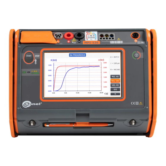
U(t), I(t) – voltage and current as a function of time, I(U) – current as a function of measuring voltage. Icons displaying the waveforms of individual parameters are shown on the right side. Return to the measurement menu with the icon MPI-536 – USER MANUAL... -
Page 94: Low-Voltage Resistance Measurement
To disable compensation of the resistance of leads, repeat steps with open test leads. Then the measurement result will contain the resistance of test leads. The meter is ready for measure- ment. MPI-536 – USER MANUAL... - Page 95 Additional information displayed by the meter Measurement in progress Incorrect voltage on object. Interference voltage occurs on the tested object. The measurement is possi- ble however it will be burdened with additional uncertainty that is specified in the technical data. MPI-536 – USER MANUAL...
-
Page 96: Measurement Of Resistance Of Protective Conductors And Equipotential Bonding With ±200 Ma Current
3 times. Then it will give the re- sult reduced by this resistance. To disable compensation of the resistance of leads, repeat steps with open test leads. Then the measurement result will con- tain resistance test leads. MPI-536 – USER MANUAL... - Page 97 Range: 0…400 Ω Functions of icons reject changes and exit to the previous screen accept changes meter ready measurement. Connect the meter to the tested object. Measurement starts automati- cally. MPI-536 – USER MANUAL...
- Page 98 NOTE! Display of symbols indicates that the tested object is live. The measurement is blocked. The meter must be immediately disconnected from the object. MPI-536 – USER MANUAL...
- Page 99 Measurement in progress. Too high voltage on the tested object. Interference voltage occurs on the tested object. The meas- urement is possible however it will be burdened with addi- tional uncertainty that is specified in the technical data. MPI-536 – USER MANUAL...
-
Page 100: Phase Sequence
Connect the meter to the installation according to the drawing. The meter ready for testing. L1-L2 L2-L3 L3-L1 values of phase-to-phase voltag- signalling the presence of indi- vidual phases The phase sequence is correct , i.e. the phase sequence is in clockwise direction. MPI-536 – USER MANUAL... -
Page 101: Motor Rotation Direction
The meter ready for testing. Connect the meter to the mo- tor according to the drawing, i.e. U terminal do input L1, V to L2, W to L3. Vigorously rotate the motor shaft to the right. MPI-536 – USER MANUAL... - Page 102 3-phase network will rotate the shaft to the left. Do not move the test leads during the test. Moving disconnected test leads, may induce voltages that result in indicating the di- rection of rotation. MPI-536 – USER MANUAL...
-
Page 103: Illuminance
Select unit. Delete the previous value and enter a new one from the range of 0…20 000 lx. Functions of icons reject changes and exit to the previous screen accept changes MPI-536 – USER MANUAL... - Page 104 Save the measurement to the meter memory using the icon. A detailed description of memory management is contained in section 5.3. MPI-536 – USER MANUAL...
-
Page 105: Auto Measurements
Description of function icons assistance for a particular measurement collapsing setting fields expanding setting fields saving entered measurement data Press START. automatic measurement sequence will start. MPI-536 – USER MANUAL... - Page 106 All sequence measurements will be saved in one measuring point. Signal lights for reaching the limit the result is within the set limit the result is outside the set limit assessment not possible no measurement was made MPI-536 – USER MANUAL...
-
Page 107: Creating Measurement Procedures
▼ From the available items select the one, which is to be a part of the procedure. In addition to standard measurements, the fol- lowing are also available: text message, visual test. MPI-536 – USER MANUAL... - Page 108 Save the procedure by using icon. A window will be shown requesting the name of the pro- cedure. The procedure will be available from the main menu of auto- procedures. To remove it, select it with and choose MPI-536 – USER MANUAL...
-
Page 109: Memory Of The Meter
SD card format. When this op- tion been selected, prompt will appear asking to confirm that the user wants to format the SD card. Description of function icons return to the previous screen return to the main menu MPI-536 – USER MANUAL... -
Page 110: Structure Of The Memory
The memory of measurement results is of a tree structure (Fig. 5.1). The user can record an un- limited number of clients. Any number of objects with sub-objects can be created in each client. Fig. 5.1. Structure of meter memory for a single client MPI-536 – USER MANUAL... -
Page 111: Fundamentals Of Navigating The Memory Menu
( ) item going to the folder tree of the active ( ) client returning to the main menu recording the active item to the SD card expanding the active item management menu MPI-536 – USER MANUAL... - Page 112 select the icon. To go to a higher level of the folder tree, select the icon. To move several levels up, select the name of the re- quired folder on the top navi- gation bar. MPI-536 – USER MANUAL...
-
Page 113: Adding A New Measurements Tree
contact person. Enter the name from the touch keypad (holding certain buttons for a longer time triggers Polish char- acters). Functions of icons rejecting changes and return- ing to step accepting changes and going to step MPI-536 – USER MANUAL... - Page 114 To go to the lower level of the tree: tap the label of the required item, activate the required item and select Creating a new client results in creating a default location for the measurements. MPI-536 – USER MANUAL...
- Page 115 Select the required item and using the icons: edit the name, remove the name. Tap to assign a location from the list to a required location of the tree ( Ok – accept all changes. Cancel – cancel changes. MPI-536 – USER MANUAL...
- Page 116 If necessary, repeat steps Using the icon expand the edit menu and select: to edit location (as in steps to enter the search mode (section 5.4), remove. MPI-536 – USER MANUAL...
- Page 117 (except autozeroing in low-voltage measurement of resistance). Complete set of results (main result and supplementary results) for a given measuring function, preset measurement settings, date and time of the measurement are stored in the memory. MPI-536 – USER MANUAL...
-
Page 118: Entering The Measurement Result
In case of cancellation, re- turn to the measurement menu using the icon. Management of objects and sub-objects id possible both in the saving to memory mode and memory viewing (section 5.4). MPI-536 – USER MANUAL... -
Page 119: Viewing Saved Measurements
Description of controls signal- ling that the set limit has been reached. condition fulfilled condition unfulfilled limit not defined To call up the measurements management menu, activate the required records ( MPI-536 – USER MANUAL... - Page 120 (step removing the active record. returning to the main menu To go to the selected meas- urement result: tap the record label, activate record ) and select value required measurement will be displayed. MPI-536 – USER MANUAL...
-
Page 121: Sharing Recorded Measurements
If necessary, select the cus- tomer ( ), which is to be subject to the requested action. Select the icon with the de- sired action. Before sending data by e-mail, the Outbox must be configured. See sec. 2.3.3. MPI-536 – USER MANUAL... -
Page 122: Searching The Meter Memory
After the icon has been selected, the option of record editing is also available in ac- cordance with section 5.2.2, steps Description of other function icons returning to the previous screen returning to the main menu MPI-536 – USER MANUAL... -
Page 123: Power Supply
Replacing rechargeable batteries MPI-536 meter is powered from SONEL Li-Ion rechargeable battery pack. Battery charger is installed inside the meter and cooperates only with the manufacturer’s re- chargeable battery pack. The charger is powered by external power supply adapter. It can be also powered from the car cigarette lighter socket. -
Page 124: Charging The Rechargeable Batteries
– error signalled by an icon on the display Due to interferences in the network or to high ambient temperature, the charging pro- cess of rechargeable batteries may finish prematurely. When charging time is too short, turn off the meter and start charging again. MPI-536 – USER MANUAL... -
Page 125: General Rules For Using Li-Ion Rechargeable Batteries
Any misuse of the battery may cause its permanent damage. This may result in the ignition. The seller and the manufacturer shall not be liable for any damages resulting from improper handling Li-Ion battery pack. MPI-536 – USER MANUAL... -
Page 126: Cleaning And Maintenance
Worn-out electronic equipment should be sent to a collection point in accordance with the law of waste electrical and electronic equipment. Before the equipment is sent to a collection point, do not dismantle any elements. Observe the local regulations concerning disposal of packages and used batteries/rechargeable bat- teries. MPI-536 – USER MANUAL... -
Page 127: Technical Data
Control of correctness of PE terminal connection by means of a touch electrode Indications of fault loop resistance R and fault loop reactance X Display range Resolution Accuracy (5% + 0.05 Ω of Z value 0...19.999 Ω 0.001 Ω < 20 Ω Calculated and displayed for Z MPI-536 – USER MANUAL... -
Page 128: Measurement Of Fault Loop Impedance Z
Control of correctness of PE terminal connection by means of a touch electrode Indications of fault loop resistance R and fault loop reactance X Display range Resolution Accuracy (6% + 10 digits) of Z 0..19.99 Ω 0.01 Ω value < 20 Ω Calculated and displayed for Z MPI-536 – USER MANUAL... -
Page 129: Measurement Of Parameters Of Rcd
n n for measurements acc. to IEC 62955 for measurements acc. to IEC 62752 Accuracy of differential current setting: for 1*I , 2*I , 5*I ..............0..8% n n n for 0.5*I ..................-8..0% n MPI-536 – USER MANUAL... - Page 130 Test range according to IEC 61557-6: 10.0 V...99.9 V Test range Test Resolution Accuracy current 0%...10% m.v. ±5 digits 0...9.9 V 0.1 V 0.4 x I n 10.0...99.9 V 0%...15% m.v. MPI-536 – USER MANUAL...
- Page 131 (does not apply to RCD EV and RCM) ........... max. 5.2 s test current duration (applies to RCD EV and RCM) ▪ acc. to IEC 62955........................30 s ▪ acc. to IEC 62752........................40 s MPI-536 – USER MANUAL...
-
Page 132: Measurement Of Resistance-To-Earth R
20.0...99.9 Ω ±(20% m.v. + 4 digits) * – at maximum interference current of 1 A Measurement with transmitting clamps N-1 and receiving clamps C-3. The range of interference current is up to 9.99 A. MPI-536 – USER MANUAL... -
Page 133: Low-Voltage Measurement Of Continuity Of Circuit And Resistance
(3% m.v. + 3 digits) 200...1999 Ω 1 Ω Voltage at open terminals: 4 V…9 V Output current < 8 mA Audio signal for measured resistance < 30 ± 50% Compensation of test leads resistance MPI-536 – USER MANUAL... -
Page 134: Measurement Of Insulation Resistance
20.0...199.9 MΩ 0.1 MΩ [(5% m.v. + 8 digits)] * 200...999 MΩ 1 MΩ (4% m.v. + 6 digits) 1.00…2.00 GΩ 0.01 GΩ [(6% m.v. + 6 digits)] * * – for WS-03 and WS-04 leads MPI-536 – USER MANUAL... -
Page 135: Light Measurements
[lx] uncertainty 0...399.9 (5% m.v. + 5 digits) 400...3999 f1<6% 4.00 k...19.99 k 0.01 k Range Resolution Spectral Accuracy [fc] [fc] uncertainty 0...39.99 0.01 (5% m.v. + 5 digits) 40.0...399.9 f1<6% 400...1999 Probe class B MPI-536 – USER MANUAL... -
Page 136: Phase Sequence
: 95 V...500 V (45 Hz…65 Hz) Range of network voltages U Display of phase-to-phase voltages 10.1.11 Motor rotation EMF motor voltage ranges: 1 V ÷ 500 V AC Test current (per phase): <3.5 mA MPI-536 – USER MANUAL... -
Page 137: Other Technical Data
....................EN 61326-1 and EN 61326-2-2 EN 55022 Compliance statement MPI-536 is a class A product. In a domestic environment this product may cause radio in- terference in which case the user may be required to take adequate measures (e.g. in- creasing the distance between affected products). -
Page 138: Additional Data
Additional uncertainty Position Supply voltage 0% for 50 V Temperature 0 °C...35 °C ± 2 digits for 25 V ±(6.5% + 5 digits) Serial interference voltage Resistance of electrodes 2.5% Frequency 99%...101% f Mains voltage 85%...110% U MPI-536 – USER MANUAL... -
Page 139: Additional Uncertainties According To Iec 61557-6 (Rcd)
[Ω] is a value of resultant resistance of multiply earthing. whereas R 10.3.5 Additional uncertainties according to IEC 61557-6 (RCD) Significant parameter Designation Additional uncertainty Position Supply voltage Temperature 0°C...35°C Resistance of electrodes Mains voltage 85%...110% U MPI-536 – USER MANUAL... -
Page 140: List Of Reference Standards
30 Hz…5 kHz 30 Hz…5 kHz Max. diameter of measured 52 mm 52 mm conductor Minimum accuracy — ≤0.3% Battery power — — Lead length Measurement III 600 V III 600 V category Ingress protection IP40 MPI-536 – USER MANUAL... -
Page 141: Positions Of The Meter's Cover
The manufacturer of the device and provider of guarantee and post-guarantee service: SONEL S.A. Wokulskiego 11 58-100 Świdnica Poland tel. +48 74 884 10 53 (Customer Service) e-mail: customerservice@sonel.com web page: www.sonel.com NOTE! Service repairs must be performed only by the manufacturer. MPI-536 – USER MANUAL... - Page 142 NOTES MPI-536 – USER MANUAL...
- Page 143 MEASURING MESSAGES NOTE! The meter is designed for operation at rated phase voltages of 110 V, 115 V, 127 V, 220 V, 230 V and 240 V and phase-to-phase voltages of 190 V, 200 V, 220 V, 380 V, 400 V, 415 V. Connecting voltage higher than allowed between any of the test terminals may damage the meter and cause a hazard to the user.
Need help?
Do you have a question about the MPI-536 and is the answer not in the manual?
Questions and answers