Advertisement
Quick Links
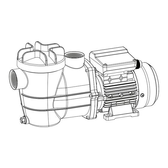
ABOVE-GROUND POOL PUMP
ITEM: 75117
0.75 HP 115 V
INSTALLATION AND USER'S GUIDE
75117
DANGER
Read all safety warnings and instructions. Failure to follow the warnings
and instructions may result in electric shock, fire and/or serious injury.
Save all warnings and instructions for future reference.
Advertisement

Related Manuals for XtremepowerUS 75117


Summary of Contents for XtremepowerUS 75117
- Page 1 ABOVE-GROUND POOL PUMP ITEM: 75117 0.75 HP 115 V INSTALLATION AND USER’S GUIDE 75117 DANGER Read all safety warnings and instructions. Failure to follow the warnings and instructions may result in electric shock, fire and/or serious injury. Save all warnings and instructions for future reference.
- Page 3 TABLE OF CONTENTS TABLE OF CONTENTS IMPORTANT SAFETY INSTRUCTIONS Legends and Symbols GENERAL SAFETY OVERVIEW (PRODUCT INFORMATION) PACKAGING CONTENTS PRODUCT DIMENSIONS SPECIFICATIONS INSTALLATION INSTALLATION LAYOUT DIAGRAM PUMP LOCATION PUMP MOUNTING PUMP DISASSEMBLY AND REASSEMBLY INSTRUCTIONS OPERATION PRIOR TO START-UP PRIMING THE PUMP TROUBLESHOOTING MAINTENANCE THE PUMP STRAINER BASKET...
- Page 4 NOTE related to hazards. USE OF NON-XTREMEPOWERUS REPLACEMENT PARTS VOIDS WARRANTY ATTENTION INSTALLER: This manual contains vital information regarding the installation, operation, and safe use of this product. It is essential to provide this manual to the end user of the product. Failure to read and follow all instructions could lead to severe injuries.
- Page 5 IMPORTANT SAFETY INSTRUCTIONS GENERAL SAFETY DANGER • Electric Shock: Hazardous voltage can shock, burn, or cause death. Licensed electricians must handle all electrical wiring. Disconnect motor wiring before working on the pump or motor. • Electrocution Risk: Failure to bond the pump to the pool structure increases the risk of electrocution.
- Page 6 IMPORTANT SAFETY INSTRUCTIONS WARNING • Separation Hazard: Secure the strainer cover properly. Never operate the system if components are damaged or missing. • Electric Shock Prevention: Replace damaged cords immediately and use only GFCI-protected circuits. CAUTION • Power Supply: Turn off the power supply before working on any electrical equipment. •...
- Page 7 OVERVIEW (PRODUCT INFORMATION) OVERVIEW (PRODUCT INFORMATION) PACKAGING CONTENTS PARTS # PARTS # PARTS PUMP STRAINER BASKET USER’S GUIDE 1 PC(S) 1 PC(S) 1 PC(S) PRODUCT DIMENSIONS 16.69" 3.15" 10.31" 9.5" 7.24" 9.98" 4.4" 5.31"...
- Page 8 OVERVIEW (PRODUCT INFORMATION) SPECIFICATIONS 115 V / 60 HZ INPUT VOLTAGE / FREQUENCY 3.6 A AMPERAGE 2400 GPH (GALLONS PER HOUR) MAXIMUM CONTINUOUS LOAD 30’ MAXIMUM SUCTION 0.75 HP HORSEPOWER 2” INLET / OUTLET DIAMETER 33’ HMAX 2400 GPH QMAX 0.45 0.095 -40°F TO +140°F (-40ºC TO +60ºC)
- Page 9 INSTALLATION INSTALLATION Installation of the pump should be carried out exclusively by a qualified plumbing professional. For further installation and safety information, please refer to the IMPORTANT SAFETY INSTRUC- TIONS section. These instructions are crucial in ensuring the proper and safe installation of the pump, thereby safeguarding against potential hazards, and ensuring optimal performance.
- Page 10 INSTALLATION PUMP LOCATION For optimal pump performance, install the system below the pool water line. Ensure the pump is placed on a firm, level base or pad that complies with all local and national codes. The base or pad must be level. Although the pump is designed for outdoor use, it is strongly recommended to protect the electri- cal components from weather exposure.
- Page 11 INSTALLATION Threaded Connections: • Use Teflon tape to seal threaded connections on molded plastic components. Do not use Plumber’s Pipe Dope as it may cause cracking of plastic components. • Wrap the entire threaded portion of the male fitting with one to two layers of Teflon tape, winding clockwise as you face the open end of the fitting, starting at the end.
- Page 12 INSTALLATION INSTALLATION INSTALLATION PUMP DISASSEMBLY AND REASSEMBLY INSTRUCTIONS Step 1: Turn Off Power • Unplug the pump or switch off the circuit breaker. Step 2: Shut Off Water Flow • Turn off the water inflow and outflow (valves). Step 3: Relieve Pressure •...
- Page 13 OPERATION OPERATION PRIOR TO START-UP Step 1: Inspect Connections • Check all hose and pipe connections to ensure they are tight and secure. Step 2: Check O-Rings • Make sure the O-rings on the strainer basket lid and other connections are in good condition and properly seated.
- Page 14 TROUBLESHOOTING TROUBLESHOOTING DANGER Before attempting any corrective actions, ensure that the pump is in the OFF position, and the breaker supplying power to the pump is also turned OFF. To avoid any potential electrical hazards, wait until the remaining power in the capacitor is fully discharged before proceeding with any work on the pump.
- Page 15 TROUBLESHOOTING ISSUE CAUSE CORRECTIVE ACTION Incorrect Voltage Check input voltage and wiring connection. Incorrect Wiring Check wiring connections. Manually check rotation of motor shaft for free Mechanical binding movement with no obstruction. Pump Hums but Ensure that the pump is properly primed before its will Not Start first use.
- Page 16 TROUBLESHOOTING ISSUE CAUSE CORRECTIVE ACTION Contact a qualified repair professional. Block off the bottom port of the skimmer to determine if pump will develop a vacuum. You should have 5”- 6” of vacuum at the strainer cover (Only your Pool dealer can confirm this with a vacuum gauge).You may be able to check by removing the skimmer basket and holding your hand over the bottom port...
- Page 17 TROUBLESHOOTING INSTALLATION ISSUE CAUSE CORRECTIVE ACTION Air leak in suction Re-tighten using Teflon tape. (bubbles issuing from return fittings). Low Flow (Cont) Plugged, restricted, or Contact a qualified repair professional. damaged impeller. Clear blockage and replace the impeller seal. Air leak in suction piping, cavitation caused by Correct suction condition or throttle return lines, if restricted or undersized...
- Page 18 MAINTENANCE MAINTENANCE THE PUMP STRAINER BASKET The unit, often referred to as the "Hair and Lint Pot," is situated in front of the volute. Inside this chamber, you'll find a basket that must be kept clean at all times to prevent leaves and debris buildup.
- Page 19 MAINTENANCE (INSTRUCTIONS CONTINED) • Thoroughly clean the cover, cover O-ring, and sealing surface. Apply grease to the O-ring using a silicone-based lubricant. • To reinstall the lid, place it on the pot, ensuring the correct positioning of the lid O-ring. •...
- Page 20 MAINTENANCE WINTERIZATION Freeze damage is not covered by the warranty, so it's essential to take precautions if the air temperature drops below 35° F. Follow the procedures listed below to prevent freeze damage: Storing Pump for Winterization • Turn off the electrical power for the pump at the house circuit breaker. •...
- Page 21 REPLACEMENT PARTS REPLACEMENT PARTS PARTS DIAGRAM ITEM REFERENCE # DESCRIPTION ITEM REFERENCE # DESCRIPTION 647251503000 COVER 65028013000 SEAL ASSEMBLY O-RING Φ107.54*Φ3.53 65431071080 647251502080 PUMP COVER SCREW M6X25 647251507001 BASKET 65224004000 647251501080 PUMP HOUSING 65023018000 MOTOR O-RING Φ40.87*Φ3.53 SCREW M5X14 65431070080 65224025000 NUT M6 647251504080...
- Page 22 DISCLAIMER DISCLAIMER PLEASE READ THE FOLLOWING CAREFULLY The manufacturer and/or distributor have provided the parts list and assembly diagram in this manual for reference purposes only. They do not make any representation or warranty to the buyer that they are qualified to make repairs to the product or replace any parts of the product. In fact, the manufacturer and/or distributor expressly state that all repairs and parts replacements should be undertaken by certified and licensed technicians, and not by the buyer.
Need help?
Do you have a question about the 75117 and is the answer not in the manual?
Questions and answers