Table of Contents
Advertisement
Quick Links
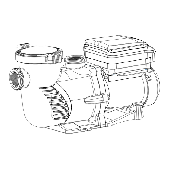
VARIABLE SPEED PUMP
1.75HP 230V 2 INCH
INSTALLATION AND USER'S GUIDE
IMPORTANT
:
Read all safety warnings and instructions. Failure to follow the warnings and instructions may result in electric
shock, fire and/or serious injury. Save all warnings and instructions for future reference.
SKU: 75408
75408
Advertisement
Table of Contents

Subscribe to Our Youtube Channel
Related Manuals for XtremepowerUS 75408


Summary of Contents for XtremepowerUS 75408
- Page 1 VARIABLE SPEED PUMP SKU: 75408 1.75HP 230V 2 INCH INSTALLATION AND USER’S GUIDE 75408 IMPORTANT Read all safety warnings and instructions. Failure to follow the warnings and instructions may result in electric shock, fire and/or serious injury. Save all warnings and instructions for future reference.
-
Page 3: Table Of Contents
TABLE OF CONTENTS TABLE OF CONTENTS IMPORTANT SAFETY INSTRUCTIONS Legends and Symbols OVERVIEW (PRODUCT INFORMATION) PRODUCT INTRODUCTION SPECIFICATION DIMENSIONS INSTALLATION LOCATION PIPING ELECTRICAL INSTALLATION OPERATION INITIAL SETUP KEYPAD FUNCTIONS INITIAL PROGRAMMING SETTING THE CLOCK USING THE DEFAULT SCHEDULE CUSTOM SCHEDULE PROGRAMMING OPERATING THE PUMP IN ACTIVE MODE PROGRAMMING QUICK CLEAN FACTORY RESET... -
Page 4: Important Safety Instructions
IMPORTANT SAFETY INSTRUCTIONS This guide provides instructions for installing and using the VARIABLE SPEED PUMP. If you have any questions about the equipment, please contact XtremepowerUS. This guide contains important information about safely installing and operating this product. After installation, make sure to share this information with the owner/operator or leave it with them for their reference. - Page 5 IMPORTANT SAFETY INSTRUCTIONS DANGER • High suction can trap and drown persons near drains or broken covers. Never use the pool or spa if covers are missing, cracked, or broken. • Never open the drive or motor enclosure due to the electrical hazard. DANGER DANGER DANGER...
-
Page 6: Overview (Product Information)
OVERVIEW (PRODUCT INFORMATION) OVERVIEW (PRODUCT INFORMATION) PRODUCT INTRODUCTION This pump boasts a variable frequency drive that ensures premium efficiency, allowing for flexible adjustments in motor speed and operation duration. Capable of functioning across a broad speed spectrum of 1000 to 3450 RPM, it is also designed to work with 230 Vrms nominal voltage at both 50HZ and 60HZ frequencies. -
Page 7: Specification
OVERVIEW (PRODUCT INFORMATION) SPECIFICATION 1.75 HP Power 2” Inlet/Outlet Connection 230V, 60HZ, 6.47A Electrical Requirements 2750 W Maximum Power Consumption 1.75 HP Maximum Shaft Horsepower 7.33 AMPS Maximum Current 111 GPM (Gallons Per Minute) Maximum Flow Rate Per Minute 75.4 FT Maximum Head Lift 1000 ~ 3450 RPM (Revolutions Per Minute) Speed Range... -
Page 8: Installation
INSTALLATION INSTALLATION • Only a qualified plumbing professional should install the pump. Refer to IMPORTANT SAFETY INSTRUCTIONS on page i-ii for additional installation and safety information. • For additional installation and safety guidelines, please consult the IMPORTANT SAFETY INSTRUCTIONS provided on page 2~3. LOCATION NOTE •... -
Page 9: Piping
INSTALLATION PIPING PIPING GUIDELINES • Using a larger pipe size is recommended for enhanced pool plumbing efficiency. • Ensure the diameter of the piping on the suction side is equal to or larger than that of the return line. • Keep the plumbing on the suction side as short as possible for optimal performance. -
Page 10: Electrical Installation
INSTALLATION ELECTRICAL INSTALLATION WARNING • Risk of Electrical Shock or Electrocution. • It is highly recommended that installation of this pump be carried out by a certified electrician or qualified professional in accordance with the National Electrical Code and local codes to avoid the risk of serious injury, death, or property damage. - Page 11 INSTALLATION BONDING INSTRUCTIONS • Connect the motor to the pool's structural metal components, electrical systems, and metal conduits and piping within 5 feet of the pool or spa's inner walls using the provided Bonding Lug on the motor's side. Comply with the current National Electrical Code and local codes for bonding practices.
-
Page 12: Operation
OPERATION OPERATION INITIAL SETUP • Prior to the initial use of the pump, program its internal clock and operational schedules. Instructions for setting the clock can be found on SETTING THE CLOCK and USING THE DEFAULT SCHEDULE, and for programming custom schedules, see CUSTOM SCHEDULE PROGRAMMING. -
Page 13: Keypad Functions
OPERATION KEYPAD FUNCTIONS FIGURE 4 Speed Time Display Duration Watts < > Setting Quick Enter Clean Start Stop SPEED 1: Press to activate Speed 1 (2850 RPM). The corresponding LED will illuminate to indicate Speed 1 is active. SPEED 2: Press to select Speed 2 (1730 RPM). An illuminated LED confirms Speed 2 is running. -
Page 14: Initial Programming
OPERATION INITIAL PROGRAMMING • Before first use, set the pump's internal clock and operational schedules as detailed in this manual. Refer to SETTING THE CLOCK in this section and CUSTOM SCHEDULE PROGRAMMING for step-by-step instructions. NOTE • When setting up a new schedule, ensure the start times for SPEED(s) 1 ~ 4 are programmed in chronological order within a 24-hour period. -
Page 15: Custom Schedule Programming
OPERATION CUSTOM SCHEDULE PROGRAMMING • Ensure the pump is halted with the Start/Stop LED off before customizing your schedule. • A blinking LED next to the parameter being edited indicates it's in programming mode. TO SET A CUSTOM SCHEDULE 1. Press Start/Stop to stop the pump. 2. - Page 16 OPERATION TO SET A CUSTOM SCHEDULE (CONTINUED) 5. Set the start time with + and - buttons, and adjust the cursor with < and >. Time adjusts in 1-hour/10-min/1-min increments. NOTE 6. Press 1 for SPEED 1 duration; DURATION will blink (refer to Figure 7). FIGURE 7 Speed Time...
-
Page 17: Operating The Pump In Active Mode
OPERATION SPEED PRIORITIZATION FOR SCHEDULING (WITHOUT EXTERNAL CONTROL) • When the pump operates under its own scheduling, the programmed speeds follow a priority sequence from highest to lowest: SPEED 1 is the top priority, followed by SPEED 2, then SPEED 3, and finally, SPEED 4 holds the lowest priority. •... -
Page 18: Programming Quick Clean
OPERATION PROGRAMMING QUICK CLEAN QUICK CLEAN FEATURE SETUP • The pump comes with a Quick Clean option, allowing temporary operation at speeds from 1700 to 3450 RPM. After a Quick Clean cycle, the pump reverts to its scheduled program. • The drive's prioritization is outlined in an accompanying table for reference. -
Page 19: Factory Reset
OPERATION PROGRAMMING QUICK CLEAN (CONTINUED) • Adjust duration in hours and minutes using "+" and "-" keys; navigate with "<" and ">". Duration steps are 1 hour or 10 minutes. NOTE Duration range: 10 minutes to 24 hours. NOTE Quick Clean duration settings won't affect the programmed start time. NOTE FACTORY RESET To revert the drive to its default settings, a Factory Reset can be executed. -
Page 20: Priming
OPERATION PRIMING CAUTION • The pump is pre-set to Priming mode, which will cause it to automatically accelerate to 3200 RPM upon initial start-up. • Before activating the pump: Open the filter's air relief valve. ◦ Ensure all necessary valves are open. ◦... - Page 21 OPERATION STARTUP AND PRIMING PROCESS (CONTINUED) • Priming duration may vary with local conditions such as water temperature, atmospheric pressure, and pool water level, all of which should be considered when choosing the priming speed. Test and adjust priming speeds multiple times, allowing the system to drain between tests.
-
Page 22: Maintenance
MAINTENANCE MAINTENANCE WARNING STRAINER POT HANDLING • Never open the strainer pot if the pump fails to prime or has operated without water. There's a risk of vapor pressure build-up and scalding water inside. • Opening under these conditions can lead to severe injury. •... -
Page 23: Moter Care
MAINTENANCE MOTER CARE HEAT PROTECTION • Shield the motor from direct sunlight. • Ensure any covering provides adequate ventilation to avoid overheating. • Facilitate good cross ventilation around the motor area. DIRT PROTECTION • Keep foreign materials away from the motor. •... -
Page 24: Pump Disassembly And Reassembly
MAINTENANCE PUMP DISASSEMBLY AND REASSEMBLY NOTE • For a detailed parts breakdown of the pump, refer to PAERTS DIAGRAM section. WARNING POWER DISCONNECTION • It is crucial to always shut off the power at the circuit breaker prior to servicing the pump. •... -
Page 25: Pump Restarting
MAINTENANCE PUMP DISASSEMBLY AND REASSEMBLY (CONTINUED) PUMP REASSEMBLY • Align the seal plate on the motor, ensuring 'UP' is at the top. • Reattach the seal plate to the motor with bolts, tightening to 70-80 in-lbs. • Hold the motor shaft and reattach the impeller onto the shaft, then the impeller screw and washer;... -
Page 26: Winterizing
MAINTENANCE PUMP RESTARTING INSTRUCTIONS (CONTINUED) • Replace the lid onto the strainer pot, securing it by turning clockwise. NOTE The lid is correctly locked when its handles are nearly perpendicular to the pump body. • Restore power to the pump at the circuit breaker. •... -
Page 27: Troubleshooting
TROUBLESHOOTING TROUBLESHOOTING WARNING ELECTRICAL SAFETY • Risk of Electrical Exposure: Diagnosis may require proximity to energized components. • Servicing is highly recommended to be performed by certified service professionals. • Hazards: Interaction with electricity can lead to death, personal injury, or property damage. ISSUE CAUSE CORRECTIVE ACTION... - Page 28 TROUBLESHOOTING NOTE • The pump is designed to automatically attempt a restart after a one-minute cooldown period. ISSUE CAUSE CORRECTIVE ACTION Obstruction by debris in Inspect the motor fan cover at the rear of the motor fan area for debris. Use compressed air for cleaning. Full or dirty strainer Refer to CLEANING THE PUMP STRAINER Noisy Pump...
- Page 29 TROUBLESHOOTING SPECIFIC FAULTS Power Out Failure: Supply voltage drops below 190 VAC, or the controller's input voltage • exceeds the limit. 16, 128 - Motor Failure to Start: This could be due to a jammed motor, improperly connected • ground wire, or misinstallation of the driver. 300 - No Load: Indicates the pump may not be drawing water.
-
Page 30: Replacement Parts
REPLACEMENT PARTS REPLACEMENT PARTS PARTS DIAGRAM 11 12 13 14 17 18 19 20 21 22 23 24 ITEM ITEM PART NO. DESCRIPTION PART NO. DESCRIPTION 647252772 COVER 65225003000 SCREW 3/8-16*1 1/2 UNC 65431042080 O-RING 65023332000 VARIABLE SPEED 1.5HP 647252704 BASKET MOTOR FOR 72559 47276801080... -
Page 31: Disclaimer
DISCLAIMER DISCLAIMER DISCLAIMER PLEASE READ THE FOLLOWING CAREFULLY The manufacturer and/or distributor have provided the parts list and assembly diagram in this manual for reference purposes only. They do not make any representation or warranty to the buyer that they are qualified to make repairs to the product or replace any parts of the product. In fact, the manufacturer and/or distributor expressly state that all repairs and parts replacements should be undertaken by certified and licensed technicians, and not by the buyer.
Need help?
Do you have a question about the 75408 and is the answer not in the manual?
Questions and answers
I have just opened my pool for summer, i need to vacuum the bottom, What speed should i run the pump at during this? But before this, priming the new pump is not working correctly. I have never had a variable speed pump, I figured out the old single speed pump, new one I don't know
The XtremepowerUS 75408 variable speed pump should be set to a higher speed, typically around 3200 RPM, for vacuuming the pool to ensure strong suction.
This answer is automatically generated