
Related Manuals for XtremepowerUS 75172


Summary of Contents for XtremepowerUS 75172
- Page 1 AUTOMATIC & MANUAL POOL COVER PUMP 1/2 HP SKU: 75172 75172 ASSEMBLY AND USER’S GUIDE...
-
Page 3: Table Of Contents
TABLE OF CONTENT TABLE OF CONTENTS INSTRUCTIONS ON APPLICATION SAFETY INSTRUCTIONS OVERALL DIMENSION INSTRUCTIONS ON THE EQUIPMENT INTRODUCTION TO THE WORKING MODE INTRODUCTION TO THE WORKING MODE INSTALLATION AND USE DAILY MAINTENANCE TROUBLESHOOTING SPECIFICATION DISCLAIMER CUSTOMER SERVICE... -
Page 4: Instructions On Application
INSTRUCTIONS ON APPLICATION Thank you for purchasing XtremepowerUS Pool Cover Pump. Before you use the equipment for the first time, please make sure to read this instruction manual and follow the contents of this instruction manual. Please keep this instruction manual appropriately for later reference. -
Page 5: Safety Instructions
SAFETY INSTRUCTIONS Please be noted that there may be life danger caused by current in case of not following safety tips. Attention! 1. Recommend setting up separate branch line for the power supply socket of the pump, and the socket power supply must conform to: 115V / 60HZ / 3.4A, with reliable grounding. - Page 6 SAFETY INSTRUCTIONS 8. Individuals with physical limitations, sensory impairments, limited understanding, or insufficient experience and knowledge are prohibited from using this equipment without the supervision or guidance of a qualified person who can provide instructions on safe equipment operation and educate them about potential hazards.
-
Page 7: Overall Dimension
OVERALL DIMENSION 8.8 INCH 12.2 INCH 6.7 INCH... -
Page 8: Instructions On The Equipment
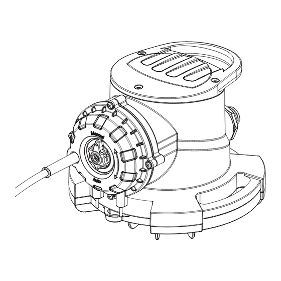
INSTRUCTIONS ON THE EQUIPMENT 1. Handle 2. Pump body 3. Base 4. Modular switch button (automatic / manual) 5. Power cord 6. Water level induction pin (two points) 7. Base hoisting rope lug 8. Air exhaust port 9. Single-direction check valve 10. -
Page 9: Introduction To The Working Mode
INTRODUCTION TO THE WORKING MODE Manual control mode 1. Rotate the knob to the Manual position. 2. Plug in the power cord. 3. Under manual mode, after plugging in the power cord, the pump will delay by 1s before starting, and the pump will run all time until the power cord is pulled off. -
Page 10: Introduction To The Working Mode
APPLICATION SCENARIO The maximal lift is 7m. Connecting hose Hoisting rope Pool cap Pool The pump for the pool cap is mainly used for draining the accumulated water on the pool cap. Attention! Place the pump on the water accumulation place in the center of the pool cap and drain the accumulated water on the tarpaulin of the pool cap through the connecting Attention! -
Page 11: Installation And Use
INSTALLATION AND USE Attention: the surface with “Out” marking of the single direction check value should be outward. - Page 12 INSTALLATION AND USE 1. Place the single direction check valve in the thread hole of the pump body, and tighten the output connector onto the water outlet of the pump and then connect the drainage hose. The surface with “Out” marking of the single direction check value should be outward.
- Page 13 INSTALLATION AND USE Power cord Connecting hose Hoisting rope 3. Place the pump on the edge of the pool cap. Prevent the power cord, hoisting rope and connecting hose from rubbing with the pool edge which may cause damages, and recommend the length of the con- Attention! necting hose to be 7.5m.
- Page 14 INSTALLATION AND USE I. Hold the hoisting rope and walk around the pool to the opposite side of the pump. II. Pull the pump to the water accumulation place at the center of the pool cap, connect the power cord, and the installa- tion of the pump is completed.
- Page 15 DAILY MAINTENANCE Screw Handle Handle air exhaust port Pump body air exhaust port Check valve Base Output connector Water inlet Screw...
-
Page 16: Daily Maintenance
DAILY MAINTENANCE In daily use, in case of performance drop, it requires cleaning the product. 1. In case the motor shell is completely airtight, it requires no repair. 2. In case the pump runs normally, but fails to pump water normally, please inspect whether the single direction 3. -
Page 17: Troubleshooting
TROUBLESHOOTING Faults Causes Troubleshooting Inspect the safety device and electrical The power supply is cut off connection Fail to reach the starting water Inspect whether the water level reaches the level. induction pin position. The pump fails to start There are foreign bodies on the or run Clean the induction pin induction pin. -
Page 18: Specification
SPECIFICATION Model 75172 Nominal Voltage 115 V / 60 HZ / 3.4 A Nominal Output 1/2 HP Max. Pump Rate 1743 GPH Max. Height 25 FT Max. grain size 1/2” NPT 1-1/4” Outlet Dia. Adapter Fitting NPT 3/4” GARDEN HOSE Water Temperature 95 °F... -
Page 19: Disclaimer
DISCLAIMER DISCLAIMER PLEASE READ THE FOLLOWING CAREFULLY The manufacturer and/or distributor have provided the parts list and assembly diagram in this manual for reference purposes only. They do not make any representation or warranty to the buyer that they are qualified to make repairs to the product or replace any parts of the product.
Need help?
Do you have a question about the 75172 and is the answer not in the manual?
Questions and answers