Advertisement
ESVK7
-
Owner's Manual
Videx Electronics S.p.A.
Via del Lavoro, 1 63024 Monte Giberto (AP) - Italy
Phone +39 0734 631669 - Fax +39 0734 632475
E-Mail info@videx.it - Web: www.videx.it
ESVK7_IT_ENG_FR_ES.indd 1
+
Series VIDEOKIT
One Way
We recommend
This equipment is installed by a
Competent Electrician, Security or
Communications Engineer.
24/07/2009 10.41.18
Advertisement
Table of Contents

Related Manuals for Videx VIDEOKIT ESVK7


Summary of Contents for Videx VIDEOKIT ESVK7
- Page 1 Via del Lavoro, 1 63024 Monte Giberto (AP) - Italy This equipment is installed by a Competent Electrician, Security or Phone +39 0734 631669 - Fax +39 0734 632475 Communications Engineer. E-Mail info@videx.it - Web: www.videx.it ESVK7_IT_ENG_FR_ES.indd 1 24/07/2009 10.41.18...
- Page 2 ESVK7_IT_ENG_FR_ES.indd 2 24/07/2009 10.41.18...
- Page 3 DESCRIPTION INTRODUCTION The ESVK7 colour video door entry kit comprises of a surface mounted door panel, 7” hands free colour monitor and power supply. The system allows communication with a visitor and the operation of a door release and/or electric gate.
-
Page 4: Specification
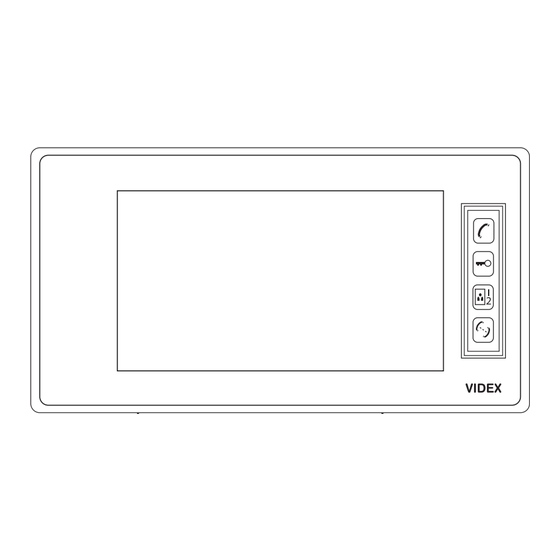
SPECIFICATION MONITOR 1. 7” hands free colour TFT monitor to display a visitors image 2. Call accept button. A single operation will allow communication with the visitor. A second opera- tion will terminate the communication and switch off the monitor. 3. - Page 5 DOOR PANEL 1. Colour CCD camera with automatic focus, built in subject light for low light vision. Additional light- ing is recommended for night operation. 2. Speaker grill. 3. Illuminated call button and name holder. Press left or right side to call. 4.
-
Page 6: Installation
INSTALLATION 1,60 m Put a silicon gasket on the upper half part between the roadside panel and the wall. Do not put silicon gasket on the lower half part in order to avoid C+ C- any vapour and premature oxidation of electronic parts. - Page 7 FM DATA C1+ C1- C2+ C2- B+ GND 1,60 m MONITOR Remove the 2 screws (3) at the base on the monitor this will allow the wall bracket to be removed, carefully disconnect the 2 mini connectors from the wall bracket. These must be replaced before re assembling the monitor.
- Page 8 CONNECTING ThE VIDEO DOOR ENTRy CONNECTION To avoid interference and possible malfunction do not run the video door entry cables in the same containment as mains or high voltage cables. 1. Carefully connect all devices in accordance with the wiring diagrams. 2.
- Page 9 VIDEO MONITOR DIP SWITCh SETTING IMPORTANT ! Depending upon the installation (1 or 2 video monitors) the position of the dip-switches on the back of each video monitor must be set correctly (see table below). Any changes to the position of the dip-switches on either the main or optional video monitor will require the power supply to be disconnected for 30 seconds and then re connected.
- Page 10 STANDARD KIT CONNECTIONS C+ C- FM DATA C1+ C1- C2+ C2- B+ GND 12Vdc Additional monitor option Additional door station option FM DATA C1+ C1- C2+ C2- B+ GND FM DATA C1+ C1- C2+ C2- B+ GND FM DATA C1+ C1- C2+ C2- B+ GND FM DATA B+ GND C+ C-...
- Page 11 SETTINGS ON ThE DOOR PANEL 2 Settings are available within the door panel. • On the upper left side, volume adjustment for door panel speaker. • On the upper right side, volume adjustment for video monitor speaker. To adjust these settings, use a small screwdriver and turn carefully without force. SETTINGS ON ThE VIDEO MONITOR 2 setting are available on the right hand side of the video monitor.
-
Page 12: Operation
OPERATION Remove the protective film from the camera lens and the video monitor screen. • Operation of the call button will initiate several call tone rings on the video monitor, the screen will be switched on and an image of the visitor will be displayed for approximately 40 seconds. • Once the visitor has been identified operation of the key will allow communication. -
Page 13: User Information
USER INFORMATION If the product fails to work switch of the power supply for at least 30 seconds, this should be carried out if the following has been undertaken: • Adding a video monitor. • Modifying the wiring. • Changing the position of dip-switches on the back of a video monitor. • A mains power failure following a thunder storm etc. - Page 14 ESVK7-HFM (MASTER) DATA ESVK7-VSU ESVK7 - STANDARD KIT Dry contact We suggest to use wires with 1.5mm section according to the following maximum distances Line Max Length from door panel to video monitor 100 metres from door panel to electric lock or gate 10 metres from video monitor to power supply 20 metres...
- Page 15 ESVK7 - STANDARD KIT We suggest to use wires with 1.5mm section according to the following maximum distances Line Max Length from door panel to video monitor 100 metres from door panel to electric lock or gate 10 metres from video monitor to power supply 20 metres from master monitor to slave monitor 20 metres...
- Page 16 Factory - Office VIDEX ELECTRONICS S.p.A. Via del lavoro,1 63020 MONTEGIBERTO (AP) - ITALY Phone: (+39) 0734 - 631669 Fax: (+39) 0734 - 632475 www.videx.it e-mail: info@videx.it Main UK office Northern UK office Danish office Greece office VIDEX SECURITY LTD...
Need help?
Do you have a question about the VIDEOKIT ESVK7 and is the answer not in the manual?
Questions and answers