
Related Manuals for Videx VK8K/6256 Series


Summary of Contents for Videx VK8K/6256 Series
- Page 1 English VIDEOKIT VK8K/6256 SERIES “6 Wire” bus one way, two way videokit VK8K VK8KC 6256 Installation handbook We recommend 66250865-EN This equipment is installed by a V 3.4 Competent Electrician, Security or 31/08/16 Communications Engineer.
-
Page 2: Table Of Contents
VK8K/6256 Series “6 wire Bus” videokit Index Introduction ....................................2 System components and available versions ..........................3 General directions for installation ..............................5 Troubleshooting guide .................................. 6 Art. 8833 Speaker unit ................................... 7 Art. 8800 - Art. 8800-3 Digital codelock module ......................... 9 8000 Series Surface and flush mounting door station installation .................. -
Page 3: System Components And Available Versions
VK8K/6256 Series “6 wire Bus” videokit System components and available versions VK8K/6256 Colour videokit. OUTDOOR INDOOR STATION STATION Videophone Art. 6256 pag. 14 Camera unit Art. 8833 pag. 7 ACCESSORIES Power supply Art. 850K pag. 5 Flush Surface Mounting Mounting Fig. 1 - VK8K/6256 components (measures in mm) - Page 4 VK8K/6256 Series “6 wire Bus” videokit System components and available versions VK8KC/6256 Colour videokit plus a codelock module. OUTDOOR INDOOR STATION STATION Videophone Art. 6256 pag. 14 Camera unit Art. 8833 pag. 7 ACCESSORIES Codelock Power supply module Art. 850K Art. 8800 pag. 5 pag.
-
Page 5: General Directions For Installation
VK8K/6256 Series “6 wire Bus” videokit General directions for installation CONNECTION TO MAINS The system must be installed according to national rules in force, in particular we recommend to: • Connect the system to the mains through an all-pole circuit breaker which shall have contact separation of at least 3mm in each pole and shall disconnect all poles simultaneously;... -
Page 6: Troubleshooting Guide
VK8K/6256 Series “6 wire Bus” videokit Troubleshooting guide In case of system failure, try the following preliminary checks: • Check that the cables are connected as shown in the installation diagram and that the cables are firmly fixed into the relevant terminals;... - Page 7 VK8K/6256 Series “6 wire Bus” videokit Art. 8833 Speaker unit When installing you see the back side of the door panel. 8833-1 Colour Aluminium 8833-2 B&W Stainless steel Fig. 1 Fig. 2 CONTROLS (SPEAKER & MICROPHONE VOLUME) Trimmer to adjust the speaker volume. Rotate clockwise to increase or anti- clockwise to decrease.
-
Page 8: Art. 8833 Speaker Unit
VK8K/6256 Series “6 wire Bus” videokit Art. 8833 Speaker unit JUMPERS J1, J2, J3 Reassurance tone volume = High Reassurance tone volume = Low Door open relay operating mode = Capacitor discharge Door open relay operating mode = Dry Contacts Only for Art. 8833-2, call buttons operating mode = each button calls a different videophone Only for Art. 8833-2, call buttons operating mode = both buttons call the same videophone... - Page 9 VK8K/6256 Series “6 wire Bus” videokit Art. 8800 - Art. 8800-3 Digital codelock module DESCRIPTION Access control system with 2 codes and 2 Relay outputs for Art. 8800 (3 codes and 3 Relay outputs for Art. 8800-3). • Engineer’s code to enter into the “Programming Menu” ( from 4 to 8 digits).
-
Page 10: Art. 8800 - Art. 8800-3 Digital Codelock Module
GENERAL DIRECTIONS FOR INSTALLATION In order to achieve the best results from the schematics described it is necessary to install only original VIDEX equipment, strictly keeping to the items indicated on each schematic and follow these General Directions for Installation: •... - Page 11 VK8K/6256 Series “6 wire Bus” videokit Art. 8800 - Art. 8800-3 Digital codelock module RE-PROGRMMING GUIDE Engineer’s code ENTER THE ENGINEER’S CODE Press Enter Relay 1 code (Red light will illu- Relay 2 code Alternatively enter a minate*) RE-ENTER THE new engineer’s code ENGINEER’S CODE...
- Page 12 VK8K/6256 Series “6 wire Bus” videokit 8000 Series Surface and flush mounting door station installation INSTALLING A FLUSH MOUNTING DOOR STATION 1. Mount back box S (Fig. 2) at 165 cm from ground level (Fig. 1); 2. If more than one flush box is needed, connect them by using the plastic spacers provided A (Fig. 2);...
-
Page 13: 8000 Series Surface And Flush Mounting Door Station Installation
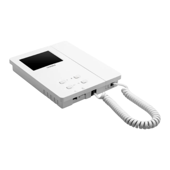
VK8K/6256 Series “6 wire Bus” videokit 8000 Series surface and flush mounting door station installation EXAMPLE: INSTALLING A TWO MODULE OUTDOOR STATION Fig. 1 Fig. 2 Fig. 3 Fig. 4 Fig. 5 Fig. 6 Fig. 7 Fig. 8 Fig. 9 Fig. - Page 14 VK8K/6256 Series “6 wire Bus” videokit Art. 6256 3.5" colour videophone 27 mm 144 mm PT3 PT2 Fig. 1 Fig. 2 DESCRIPTION Surface mount videophone incorporating a 3.5” Hi-Res full colour active matrix LCD monitor specific for “6 wire” videokit (VK4K, VRVK and VK8K range).
-
Page 15: Art. 6256 3.5" Colour Videophone
VK8K/6256 Series “6 wire Bus” videokit Art. 6256 3.5" colour videophone LEDS CONTROLS Door open LED. SW1 Call tone volume controll (3 levels). Can be used to indicate the status of a door or gate. It requires a switched 12Vdc connection to terminal “LD” . - Page 16 VK8K/6256 Series “6 wire Bus” videokit Art. 6256 3.5" colour videophone SIGNALS ON CONNECTION BOARD 20Vdc Input/Output (As input 16÷20Vdc 0,5A – as output 20Vdc 0,5A max) – Ground reference for +V terminal. Speech line output from handset’s microphone and data signal (Approx. 12V in stand-by, 5V during a conversation) Speech line input toward the handset’s loudspeaker (Approx.
- Page 17 VK8K/6256 Series “6 wire Bus” videokit 6200 Series Videophone wall mounting instructions Fig. 1 Fig. 2 Fig. 3 Fig. 4 Fig. 5 Fig. 6 1. In order to install the videophone, it is necessary to remove the cover, which contains all the electronics, from the base: firstly disconnect the handset from the videophone (by removing its plug from the videophone), then press lightly the bottom part of the videophone and simultaneously pulling outwards the upper part as shown in Fig.
-
Page 18: Installation Diagrams
This manual has been written and revised carefully. The instructions and the descriptions which are included in it are referred to VIDEX parts and are correct at the time of print. However, subsequent VIDEX parts and manuals, can be subject to changes without notice. - Page 19 VK8K/6256 Series “6 wire Bus” videokit Installation diagrams VIDEOKIT VK8K-1/6256, VK8K-1S/6256 Local Bell Art.6256 Address N. 1 Ext. 1 In caso di modifica alle impostazioni dei dip switch del videocitofono o del posto esterno, togliere temporaneamente l'alimentazione di rete. In order to make the system recognize any modification of the...
- Page 20 VK8K/6256 Series “6 wire Bus” videokit Installation diagrams VIDEOKIT VK8K-2/6256, VK8K-2S/6256 1 2 3 4 5 6 7 8 1 2 3 4 5 6 7 8 04/11/2015 17/11/2015 Marco Rongoni vk8k62h-003.dwg VK8K/6256 Series - Installation handbook 66250865-EN - V 3.4 - 31/08/16...
- Page 21 VK8K/6256 Series “6 wire Bus” videokit Installation diagrams VIDEOKIT VK8KC-1/6256, VK8KC-1S/6256 Local Bell Art.6256 Address N. 1 Ext. 1 In caso di modifica alle impostazioni dei dip switch del videocitofono o Art.8800 del posto esterno, togliere temporaneamente l'alimentazione di rete.
- Page 22 VK8K/6256 Series “6 wire Bus” videokit Installation diagrams VIDEOKIT VK8KC-2/6256, VK8KC-2S/6256 1 2 3 4 5 6 7 8 1 2 3 4 5 6 7 8 17/11/2015 01/12/2015 Marco Rongoni vk8k62h-005.dwg VK8K/6256 Series - Installation handbook 66250865-EN - V 3.4 - 31/08/16...
- Page 23 VK8K/6256 Series “6 wire Bus” videokit Installation diagrams VIDEOKIT VK8K-1/6256, VK8K-1S/6256 WITH ADDITIONAL INTERCOM AND EXTENSION SOUNDER Local Bell Affinche qualsiasi modifica alle impostazioni dei dip switch del videocitofono o del posto esterno venga riconosciuta dal sistema, è necessario togliere l'alimentazione di rete all'impianto e restituirla.
- Page 24 VK8K/6256 Series “6 wire Bus” videokit Installation diagrams VIDEOKIT VK8K-2/6256, VK8K-2S/6256 WITH ADDITIONAL DOOR PANEL FOR 2 ENTRANCES SYSTEM Local Bell In caso di modifica alle impostazioni dei dip switch del videocitofono o del posto esterno, togliere temporaneamente l'alimentazione di rete.
- Page 25 VK8K/6256 Series “6 wire Bus” videokit Installation diagrams VIDEOKIT VK8KC-1/6256, VK8KC-1S/6256 WITH 3 ADDITIONAL VIDEOPHONES 1 2 3 4 5 6 7 8 1 2 3 4 5 6 7 8 1 2 3 4 5 6 7 8 01/12/2015...
- Page 26 VK8K/6256 Series “6 wire Bus” videokit Installation diagrams VIDEOKIT VK8K-2/6256 - VK8K-2S/6256 WITH ART. 316 1 2 3 4 5 6 7 8 1 2 3 4 5 6 7 8 21/10/2015 17/11/2015 Marco Rongoni vk8k62h-001.dwg VK8K/6256 Series - Installation handbook...
- Page 27 VK8K/6256 Series “6 wire Bus” videokit Installation diagrams TWO ENTRANCES SYSTEM INSTALLATION 18Vdc ART. 323/18 230V Push to Push to Exit Exit Art.8833-2 Art.8833-2 ID:1 ID:2 Title: Data creazione: Foglio 28/10/2015 Titolo: Data modifica: 28/10/2015 Videx Electronics S.p.A. Notes: Autore:...
- Page 28 MANUFACTURER CUSTOMER SUPPORT VIDEX ELECTRONICS S.P.A. All Countries: Via del Lavoro, 1 - 63846 Monte Giberto (FM) Italy VIDEX ELECTRONICS S.P.A. www.videx.it - technical@videx.it Tel (+39) 0734 631669 - Fax (+39) 0734 632475 Tel: +39 0734-631669 - Fax: +39 0734-632475 www.videx.it - info@videx.it...
Need help?
Do you have a question about the VK8K/6256 Series and is the answer not in the manual?
Questions and answers