EUROSTER 2006, 2006TX Manual
- Installation and operation manual (13 pages) ,
- Installation and operation manual (15 pages)
Advertisement
- 1 SPECIFICATION
- 2 CHOOSING INSTALLATION LOCATION
- 3 OUTSIDE VIEW OF THE UNIT
- 4 TO OPEN TOP HOUSING
- 5 CHOOSING OPERATION MODE & TO REPLACE BATTERIES
- 6 WIRING GUIDE
- 7 TO ADJUST HYSTERESIS
- 8 TO ADJUST TEMPERATURE CALIBRATION
- 9 TO ADJUST CLOCK
- 10 TO ADJUST TEMPERATURE SETTING
- 11 TO SET PROGRAM-PERIOD FOR EACH DAY AND START SETTING
- 12 SET UP THE SAME PROGRAMS FOR THE WHOLE WEEK
- 13 FACTORY PRESET PROGRAM-PERIOD
- 14 TO SET HOLD
- 15 TO SET 5°C ANTI-FREEZE PROTECTION
- 16 TO SET MANUAL
- 17 RESTORING PRE-PROGRAMMED SETTINGS
- 18 SET CONTENTS
- 19 EUROSTER TXRX WIRELESS VERSION
- 20 TROUBLESHOOTING LIST
- 21 MAINTENANCE
- 22 SAFETY RULES
- 23 Documents / Resources
SPECIFICATION
- EEPROM memory backup
- for Heating or Cooling, by factory preset
- temperature display range: 0 ~ 50°C
- temperature control range: 5 ~ 35°C for Room mode, 5 ~ 45°C for Floor-heating mode
- temperature sampling rate: 1 minute
- switching differential(Hysteresis): 0.2°C, 0.4°C or 1°C selectable to users

- temperature sensing calibration: ± 2°C
- temperature adjusting scale: 0.1°C (fast forward adjusting function, pressing + or - for 3 seconds)
- temperature display scale: 0.1°C
- all 7-Day independently programmed
- 24-Hour- format, spread into 48 time adjusting zone
- thermostat operate Power: 2 X AA 1.5 Vdc LR 6 Alkaline Battery-low indication (when power goes below 2.4 Vdc)
- thermostat output: 16(3.5) AMP / 250 V ac, Voltage-free, SPDT.
- dimension: 138 L x 86 W x 29 H mm

CHOOSING INSTALLATION LOCATION
For obtaining thermostat's best performance upon using, recommend user to follow up with precaution listed below.
- Place thermostat on wall inside the room approximate 1.5 meter above floor.
- Avoid position where temperature sensing easily interfered by ambience, such as, directly exposed to Sun-Light, too near to any Heat-Generate devices/refrigerator, right next to entrance/ exit/window, etc.
- Prevent thermostat from installed at position that furniture may interfere air-flow, stagnant air-flow location is not suitable for installing thermostat.
- Keep thermostat away from high humid ambience, high humidity is hazardous to thermostat's operational duration.
- It's crucial, before installing thermostat, make sure house renovation is finished, no tacky painting/plaster is right on thermostat's installing position.
- To level thermostat prior to installation is not necessary.
- Push excess cable wires back into the wall while positioning thermostat. If there is a draft, pack the opening with non-combustible material.
- Place batteries in thermostat requiring batteries, observing " +" and "-" positions.
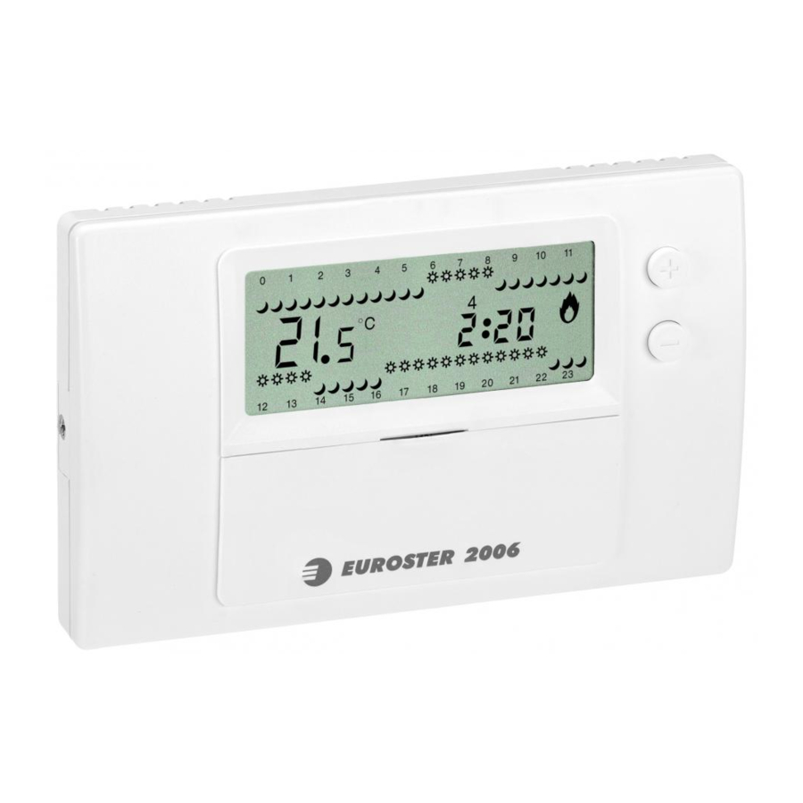
OUTSIDE VIEW OF THE UNIT

BODY
- HOLD – use the button to switch the thermostat into the manual mode. The thermostat maintains the set temperature regardless of programmed settings. Press the
![]() button again to restore operation with programmed settings.
button again to restore operation with programmed settings. - economical temperature — Press
![]() to display the current economical temperature.
to display the current economical temperature. - comfort temperature — Press
![]() to display the current comfort temperature.
to display the current comfort temperature. - Setting the clock.
- Restarting the thermostat.
- A knob used to select weekdays when programming a thermostat.
- Multi-purpose setting button:
![]() increase
increase - Multi-purpose setting button:
![]() decrease.
decrease.
 button again to restore operation with programmed settings.
 to display the current economical temperature.
 to display the current comfort temperature.
 increase
 decrease.
DISPLAY
- Temporary temperature change — MANUAL sign is displayed to indicate that the temperature has been changed manually by means of setting buttons.
- An icon indicating activation and operation of the controlled device.
- Indication of current time.
- Current weekday, with 1 for Monday and 7 for Sunday, here: Wednesday.
- Indication of current temperature.
- Indication of time in 24-hour mode.
- The
![]() icon over or under the indication of time determines the period of thermostat operation with comfort temperature setting.
icon over or under the indication of time determines the period of thermostat operation with comfort temperature setting. - The
![]() icon over or under the indication of time determines the period of thermostat operation with economical temperature setting.
icon over or under the indication of time determines the period of thermostat operation with economical temperature setting.
TO OPEN TOP HOUSING

Using the Philips screwdriver, release the screw that keeps front and back parts of the housing together. Beginning from the left side, open the thermostat. Take care of two hooks located on the right side of thermostat.
CHOOSING OPERATION MODE & TO REPLACE BATTERIES

J4 - Selection of Cool or Heat mode

J1 - Selection of Floor - sensor or Room - sensor mode

Switches the heating off when battery is empty.
Note: Option is not available in wireless versions.
Battery 2xAA. Follow „+" and „-" instruction.
WIRING GUIDE

TO ADJUST HYSTERESIS
- Point Rotary switch to "RUN".
![]()
- Press and hold both
![]() and
and ![]() for 3 seconds.
for 3 seconds. - Shown as on LCD, to press either
![]() or
or ![]() to select required Hysteresis.
to select required Hysteresis. - Wait for 5 seconds, after adjustment, thermostat shall automatically memorize adjustment and begin operating.

 for 3 seconds.
TO ADJUST TEMPERATURE CALIBRATION
- Point Rotary switch to MON.
- Press and hold both
![]() and
and ![]() for 3 seconds.
for 3 seconds. - Shown as on LCD, to press either
![]() or
or ![]() to set temperature calibration.
to set temperature calibration. - Wait for 5 seconds after calibration was done, Thermostat shall automatically memorize
 and
and  for 3 seconds.
TO ADJUST CLOCK
- Rotary switch pointed to "RUN".
- Press
![]() to enter clock adjusting.
to enter clock adjusting. - Press
![]() or
or ![]() to select the day of week.
to select the day of week. - Press
![]() again to enter adjusting hour of day.
again to enter adjusting hour of day. - Press
![]() or
or ![]() to adjust.
to adjust. - Repeat procedure of pressing
![]() and
and ![]() to finish adjusting minute of hour.
to finish adjusting minute of hour. - LCD display shall automatically return to main page in 5 seconds after clock adjusting completed.
 to finish adjusting minute of hour.
TO ADJUST TEMPERATURE SETTING
- Rotary switch pointed to RUN.
- Press
![]() to enter
to enter ![]() temperature setpoint. Press
temperature setpoint. Press ![]() to enter
to enter ![]() temperature setpoint.
temperature setpoint. - Press
![]() again, LCD display begins flashing.
again, LCD display begins flashing. - Press
![]() or
or ![]() to adjust temperature.
to adjust temperature. - Wait 5 seconds after temperature adjustment finished, thermostat shall memorize setting and return to main page.
 again, LCD display begins flashing.
With two temperatures setting only, each of 7-day is spread into 48 independent timescale, users can select length of time by own preference, to coordinate with ![]() and
and ![]() temperature setting, for coziest room temperature.
temperature setting, for coziest room temperature.
TO SET PROGRAM-PERIOD FOR EACH DAY AND START SETTING
- Rotary switch pointed to the desired day of week.
- LCD display shall show

- Press
![]() or
or ![]() to alter setting between b and a on LCD display.
to alter setting between b and a on LCD display. - Press
![]() or
or ![]() to select each individual time-scale, LCD display shall also indicate each time-scale by digital number and flashing, to guide users.
to select each individual time-scale, LCD display shall also indicate each time-scale by digital number and flashing, to guide users. - After finished setting all 7-day of week, spin rotary switch back to "RUN". Thermostat starts to operate its program.

 or
or  to select each individual time-scale, LCD display shall also indicate each time-scale by digital number and flashing, to guide users.
SET UP THE SAME PROGRAMS FOR THE WHOLE WEEK
- Point Rotary switch to MON.
- Set the program for Monday.
- Press and hold the
![]() button for 2 seconds - now the Monday settings will be copied to all days of the week.
button for 2 seconds - now the Monday settings will be copied to all days of the week. - The digits 1234567 will be displayed.

- Spin rotary switch back to "RUN"
 button for 2 seconds - now the Monday settings will be copied to all days of the week.
FACTORY PRESET PROGRAM-PERIOD
Heating mode  21.0°C
  20.0°C
Cooling mode 22.2°C 25°C

Pre-programmed time intervals:
Monday to Friday from 6:00 am to 10:00 pm from 10:00 pm to 6:00 am
Saturday and Sunday from 6:30 am to 10:30 pm from 10:30 pm to 6:30 am
TO SET HOLD
(PERMANENT OVERRIDE)
- Rotary switch pointed to RUN.
- Press
![]() to enter this permanent override mode, LCD shall display "Temp Set" "Hold".
to enter this permanent override mode, LCD shall display "Temp Set" "Hold". - Press
![]() or
or ![]() to adjust temperature setting.
to adjust temperature setting. - LCD display shall be flashing for approximate 8 second after temperature setting finished, and skip to indicate ambient temperature after flashing stopped. Thermostat starts to execute Permanent-Override function.
- Press again
![]() , shall deactivate this "HOLD" command, thermostat shall resume its scheduled programs executing.
, shall deactivate this "HOLD" command, thermostat shall resume its scheduled programs executing.
 , shall deactivate this "HOLD" command, thermostat shall resume its scheduled programs executing.
TO SET 5°C ANTI-FREEZE PROTECTION
- Rotary switch pointed to RUN.
- To enter this mode, press and hold
![]() button for 5 seconds, until A - F is shown on LCD.
button for 5 seconds, until A - F is shown on LCD. - Release
![]() button - Anti-Freeze protection is being started.
button - Anti-Freeze protection is being started. - Press
![]() again to deactivate Anti-Freeze Protection, thermostat shall resume its scheduled programs executing.
again to deactivate Anti-Freeze Protection, thermostat shall resume its scheduled programs executing.

Regardless of the activation moment, Anti-Freeze Protection is active until Monday, 0:00.
TO SET MANUAL
(TEMPORARY OVERRIDE)
- Rotary switch pointed to RUN.
- Press
![]() or
or ![]() LCD display shall indicate current
LCD display shall indicate current ![]() or
or ![]() temperature setting.
temperature setting. - Press again
![]() or
or ![]() to change setting.
to change setting. - LCD display shall be flashing for approximate 8 second after temperature setting finished, and skip to main page of LCD-display after flashing stopped. Thermostat starts to execute "MANUAL" function.
- Thermostat shall maintain executing "MANUAL" until
![]() program runs to the section of
program runs to the section of ![]() . Vice versus. On LCD-display main page, when MANUAL in executing
. Vice versus. On LCD-display main page, when MANUAL in executing ![]() or
or ![]() shall disappear from display at the section of time that **MANUAL** function is executing.
shall disappear from display at the section of time that **MANUAL** function is executing. - Spin switch away from "RUN" and spin it back to "RUN" can terminate this "MANUAL" function.

 or
or  temperature setting.
RESTORING PRE-PROGRAMMED SETTINGS
- Press simultaneously
![]() and
and ![]() buttons and hold them while pressing RESET button.
buttons and hold them while pressing RESET button. - Release all buttons.
- Press
![]() button twice and RESET button again.
button twice and RESET button again.
SET CONTENTS
- EUROSTER 2006
- User manual
- 2 x alkaline batteries
- 2 x screws
EUROSTER TXRX WIRELESS VERSION
GENERAL DESCRIPTION
The programmable temperature controller EUROSTER in the TXRX wireless version is, in terms of programming, the equivalent of EUROSTER wired version. In the packaging there is a user guide for the appropriate wired model. The difference is in how the on / off signal is transmitted.
With the EUROSTER TXRX controller the signal is transmitted wirelessly by radio, eliminating the need for wiring between the controller EUROSTER TX, and the device controlled by the receiver EUROSTER RX.
The effective range of operation depends to a large extent on the materials of which the building is made. EUROSTER TX, in conjunction with the receiver RX, provides coverage of about 100 m in open area. In buildings this distance reaches 30 meters which means the signal is able to cross several storeys. The signal is strongly attenuated by reinforced concrete structures which results in significantly reduced coverage.
Low battery indicator will be visible when the battery voltage drops to a minimum acceptable level. It is recommended to replace the batteries with new alkaline ones, every season. If needed, the controller must be reprogrammed.
OUTSIDE VIEW

- Receiving the signal from the transmitter indication- green LED.
- Receiving device (e.g. heating) activated indication - red LED.
- Switch for continuous operation of the heating appliance (can be turned on in the event of damage to the system). In an automatic mode the switch should remain in position 0.
- Output cable.
- Output connector - volt-free
- contacts COM - NO normally open (most commonly used)
- contacts COM - NC normally closed
- Antenna - should be pulled out totally during the operation.
FIRST LAUNCH OF THE UNIT
The receiver voltage is life-threatening, therefore electricity supply should be absolutely detached during the installation and the assemblage be entrusted to a qualified installer. Do not install the controller showing signs of mechanical damage.
- Insert new alkaline batteries.
- Pull the telescopic antenna on the receiver RX out to its maximum.
- After a few seconds the green LED should blink - the receiver is within the range of the transmitter. In order to verify coverage, after connecting the TXRX kit, the transmitter sends a signal every 3 seconds during the first minute (green LED blinking). Afterwards, the process is repeated every 1 minute and lasts about 1 second. No indication means insufficient coverage.
- Active red LED means the heating (or cooling) device is turned on.
PROTECTION
- If the receiver module EUROSTER RX does not receive a confirmation of activation or deactivation during 7 consecutive cycles (due to disruption of transmission by e.g. a strong electromagnetic pulse or due to battery voltage drop in EUROSTER TX), the heating appliance is turned off. This prevents the device from overheating. After the disruption is eliminated the system automatically returns to work, with the exception of battery replacement, which requires reprogramming of the TX controller.
- In addition, the receiver RX is equipped with an Anti-freeze system. This function is active only in case of loss of communication with the transmitter (discharged battery, interference). Such a state is indicated by fast flashing of the green LED, and follows 7 consecutive missed pulses from the transmitter. If this condition persists for a longer time, the receiver is automatically turned on for twenty minutes every three hours, so as not to lead to cooling of the rooms. As soon as the communication is re-established (disruption disappearance, batteries replaced) the receiver automatically turns off and the system returns to operate with the transmitter TX.
- The signal sent to EUROSTER RX has a nature of coded digital transmission. This allows for an operation of multiple EUROSTER TX controllers on a small area without fear of cross-interference. When using two receivers RX always keep them at least 0.5 m from each other. Controllers are always paired with receivers of the same code and there is no possibility of exchange of a single module. The code is printed on the receiver RX (sticker at the plug side) and the controller TX (transmitter) on the left side of the battery compartment or on the back of the housing.
However, if doubts in this respect arise, please contact the dealer or the manufacturer.
OPERATION
Because of the one-way signal transmission and safety of the user of heating (or cooling) equipment, EUROSTER TX sends every minute a short coded message confirming the status of the relay of the EUROSTER RX receiver. It is indicated by lighting of the green LED for about 1 second. For this reason, the indicator of the controller can light up earlier than the control device is turned on. Time difference should not be greater than 1 min. Similar situation may occur when turning the heating appliance off. Given the heat capacity of the buildings, this is not significant to the economy of regulation and has no effect on the cost of heating.
An electrical, oil or gas appliance, consuming more power than the maximum load of contacts, can be connected only through an external relay with appropriate characteristics. If in doubt, please consult the distributor or manufacturer.
Large inductive and capacitive loads should be avoided as they cause burnout of the relay's contacts.
Green light on the receiver RX indicates:
- receiving a signal from the transmitter - lights up every 1 minute for about 1s
- lack of communication - indicated by rapid flashing (caused by 7 consecutive missed connections)
Fast pulsing of the green LED means also
- distance of the receiver from the transmitter too long (reduce the distance)
- discharged batteries (replace with new alkaline ones). Partially discharged batteries can cause a decrease of the signal range - battery replacement is advised
Red LED indicates that the heating function of the boiler (or other device) is switched on.
WIRING DIAGRAM
Presented diagrams are simplified and do not contain all the elements needed for the correct operation of the system.

With a 230 V AC powered device
- Electrical connector cube
- Output wire, contacts used COM - NO - (normally open)
- Antenna
- Euroster RX (receiver)
- Euroster TX, placed in any room

With a gas boiler
- Electrical connector cube
- Output wire, contacts used COM - NO - (normally open)
- Antenna
- Euroster RX (receiver)
- Euroster TX placed in any room

With a CH pump
- Central heating boiler
- Shut-off valve
- Strainer
- CH pump
- Return valve
- Heat receiver – heater
- EUROSTER TX (transmitter)
- EUROSTER RX (receiver)
- Antenna
- Electrical connector cube
- Output wire, contacts used COM - NO (normally open)
RECEIVER RX TECHNICAL DATA
Supply Voltage: 230 V 50 Hz
Maximum load: 5 A 230 V 50 Hz
Protection class: II
Radio frequency: 433.92 MHz
Maximum power of transmission: <10mW
Output cable length: 2 m
Dimensions: 112 x 64 x 68 mm
In case of a complaint the complete EUROSTER TXRX must be supplied to the point of sale with the warranty card.
SET CONTENTS
- EUROSTER TX
- EUROSTER RX
- Controller holder
- User manual
- 2 x alkaline batteries
TROUBLESHOOTING LIST
The unit does not switch on the heating appliance
- replace the batteries - use only new alkaline batteries
- reset and program the controller
- move the controller to another place
- verify the operation of LEDs on the receiver unit (green and red)
- verify connection between the receiver and the controlled appliance
- disconnect the receiver unit from the controlled appliance and check the operation of the latter;
- check if the code given on the transmitter is the same as on the receiver
- fully extend the antenna
Blinking LCD display on the unit
- replace the batteries - use only new alkaline batteries
- reset and program the controller
Blinking battery charge indicator on the LCD display
- replace the batteries - use only new alkaline batteries
- make sure the battery contacts are clean
Lack of windmill icon on the LCD display, which indicates that the appliance is switched off:
- verify the setting of DIP switches on the controller
- verify the settings of operating parameters: day, hour, temperature
MAINTENANCE
Do not use solvents and aggressive detergents to clean the thermostat, since they may damage the surface of the housing and the display. Clean the thermostat housing with a soft cloth (dry or slightly moistened with a mild detergent). Please remember to change the batteries, since leakage of the electrolyte may cause an irreversible damage to the thermostat.
SAFETY RULES
- It is necessary to read this user manual carefully prior to the commencement of the installation works. Incorrect installation and improper use may lead to a serious hazard to a user or other persons and result in material damage!
![]()
Voltages hazardous to life may be present on the thermostat output cables, therefore only qualified technicians may install the thermostat!- Do not install the controller in rooms of increased humidity, substantial dustiness or with presence of caustic or flammable vapors, protect it against water and other liquids!
- Do not install any thermostats showing signs of mechanical damage!
- Do not misuse the controller!
- The controller is not a safety component of the heating system in the systems with a risk of damage. In the case of failure of control systems, use additional protective equipment!

MANUFACTURER: P.H.P.U. AS, ul. Polanka 8a/3, 61-131 Poznań, Poland
Documents / ResourcesDownload manual
Here you can download full pdf version of manual, it may contain additional safety instructions, warranty information, FCC rules, etc.
Advertisement


Need help?
Do you have a question about the 2006 and is the answer not in the manual?
Questions and answers