ENFORCER E-931-S35RRQ Manual
- Installation manual (2 pages) ,
- Installation manual (4 pages)
Advertisement
Introduction
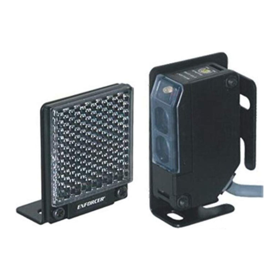
The ENFORCER E-931-S35RRQ Retro-Reflective Photoelectric Beam Sensor provides reliable sensing of objects that enter the space between the sensor and reflector, thus breaking the infrared beam. It is suitable for various types of such as detection such as sensing approaching vehicles to open a garage door or outdoor gate, as an entry notification for stores, for measuring parking distances, industrial automation, or an alarm notification, as well as many other uses.
- Range 35ft (11m)
- Weatherproof (IP66) construction for indoor/outdoor usage
- Dark ON operation (Light ON operation also available)
- Pre-wired 6ft (1.8m) cord
- Bracket and mounting hardware included for both sensor and reflector
- Adjustable sensing range
- Compact size

- This sensor was not designed to prevent bodily injury or loss of life.
- This sensor was not designed for use in environments where explosive gases may be present.
- Use of this sensor in certain security applications may be regulated by local laws or codes. SECO-LARM is not responsible for compliance with such laws or codes
Parts List
1x Sensor
1x Square reflector
1x Sensor mounting bracket
1x E-931ACC-BLR2Q Reflector mounting bracket
All mounting hardware
1x Manual
Specifications
| Type | Retro-reflective | |
| Operating voltage | 24~240 VAC/12~240VDC | |
| Sensing range | 0.5~35 ft (0.2~11 m) | |
| Current draw | Standby | 25mA@12VDC |
| Active | 60mA@12VDC | |
| Response time | 10ms, (max.) | |
| Light source | IR LED | |
| LED indicators | Yellow LED (Alignment), Red LED (Triggered) | |
| Trigger output | SPDT Relay output (NO/NC/COM) | |
| Switching capacity | 1A@250VAC/2A@30VDC | |
| IP Rating | IP66 Weatherproof | |
| Operating temperature | -4~131°F (-20~55°C) | |
| Sensor dimensions | 13/16" x 25/8" x 19/16" (20x66x40 mm) | |
Dimensions

Sample Installations

Installation and Adjustment
LED Functions

- Red LED – When ON, indicates the sensor is triggered.
- Yellow LED – When ON, indicates the sensor is properly aligned with the reflector, and not triggered.
Understanding Sensing Range Adjustment
The Sensing Range adjustment determines the strength of the infrared signal emitted by the sensor.
- Min. Setting – Weakest infrared signal – sensor easily be triggered by small objects but more susceptible to false alarms
- Max. Setting (default) – Strongest infrared signal – sensor less likely to be susceptible to false alarms
Installation
- Mount the reflector and the sensor so they face each other (see Mounting the Reflector, below and Mounting the Sensor).
- Connect power to the sensor (see Wiring Diagram). The red LED will probably light, indicating that the sensor and reflector are not yet aligned. If the yellow LED lights (red LED OFF), it indicates that the sensor and reflector are aligned (though it may still be necessary to further adjust the alignment).
- Turn the sensing range knob to Max.
- To find the best alignment, slowly adjust the angle of the sensor (and/or reflector) up, down, left or right.
NOTES:
- Correct alignment is reached when the red LED is OFF and the yellow LED is ON.
- If both LEDs are OFF, the sensor is at the edge of signal range and may not work properly.
Adjusting Sensing Range
After the sensor and the reflector have been properly installed, the next step is to adjust the appropriate setting for the sensing range.
- Starting from the Min. position, slowly turn the sensing range adjustment (see Fig. 2) clockwise until the yellow LED turns ON Mark this as position A.
![]()
NOTE: If the yellow LED is on at the Min. setting, consider this as position A. - Place an object similar to what you desire to detect between the sensor and reflector at the point where you would normally want it to be detected. The yellow LED should turn off and the red LED should turn on.
- Slowly turn the sensing range adjustment clockwise until the yellow LED turns on again. Mark this as position B.
NOTE: If the yellow LED does not turn on even at the Max. position, then consider Max. as position B. - Turn the sensing range adjustment counterclockwise to a point approximately midway between points A and B.

Testing
- Power up the sensor. The yellow LED should be ON and the red LED should be OFF.
- Pass a typical object to be detected between the sensor and reflector. The red LED should turn ON and the yellow LED OFF indicating successful detection.
NOTE: If a shiny object, such as a chrome-plated item or one with reflective tape, comes in close proximity to the IR beam, the sensor may not be able to detect accurately. If so, you may need to adjust the sensing range counterclockwise until the desired results are obtained.
Mounting the Reflector

Wiring Diagram

NOTES
- Can be connected to AC or DC voltage
- Maximum cable extension length is 325ft (100m)
Mounting the Sensor

Troubleshooting
| Sensor does not detect the object |
|
| Yellow LED does not turn on |
|
| Red LED lights when object is detected, but no output |
|
Accessories


Users and installers of this product are responsible for ensuring that the installation and configuration of this product complies with all national, state, and local laws and codes. SECO-LARM will not be held responsible for the use of this product in violation of any current laws or codes.

California Proposition 65 Warning: These products may contain chemicals which are known to the State of California to cause cancer and birth defects or other reproductive harm. For more information, go to www.P65Warnings.ca.gov.
SECO-LARM® U.S.A., Inc.
16842 Millikan Avenue, Irvine, CA 92606
Phone: (949) 261-2999 | (800) 662-0800
Website: www.seco-larm.com
Email: sales@seco-larm.com
Documents / Resources
References

Download manual
Here you can download full pdf version of manual, it may contain additional safety instructions, warranty information, FCC rules, etc.
Advertisement


Need help?
Do you have a question about the E-931-S35RRQ and is the answer not in the manual?
Questions and answers