Brig Eagle 3.5, E3.5, E3.5H - Eagle Series Boats Manual
- Owner's manual (38 pages) ,
- Owner's manual (36 pages) ,
- Owner's manual (36 pages)
Advertisement
- 1 IDENTIFICATION PLATE
- 2 TECHNICAL SPECIFICATIONS
- 3 COMPLETE SET
- 4 PRODUCT DESIGN
- 5 LOCATION OF THE MAIN SYSTEMS
- 6 BUOYANCY TUBE
- 7 TUBE INFLATION
- 8 STEERING CONSOLE
- 9 SWITCH PANEL AND FUSE BOX
- 10 WIRING DIAGRAM
- 11 BATTERY INSTALLATION
- 12 FUEL SYSTEM
- 13 DRAIN SYSTEM
- 14 CREW LIMIT
- 15 TOWING
- 16 MOORING
- 17 PRODUCT TRAILERING
- 18 THE MAIN DIMENSIONS
- 19 MAINTENANCE
- 20 OPERATING REGULATIONS
- 21 WARNING SIGNS AND LABELS
- 22 SAFETY REGULATIONS
- 23 ALWAYS REMEMBER ABOUT FIRE DANGER
- 24 DANGER LEVELS
- 25 Documents / Resources
IDENTIFICATION PLATE

Builder's Plate

Plate with identification number
ATTENTION
It is fundamental for the plates to be aboard the boat, since they are only f orm of recognition and identification. W ithout them the boat does not comply with the legislation in effect. The plates must never be removed. Any tampering or removal not authorised by the manufacturer is the full responsibility of the owner.
TECHNICAL SPECIFICATIONS
The basic parameters and dimensions of the boat Eagle 3.5 comply with the data specified in the following table.
All dimensions measurments indicated have a tolerance of +/- 3%, weight measurments indicated have a tolerance of +/- 5%.
| Parameter | Eagle 3.5 |
| Length (without engine) | 3.50 m |
| Beam | 1.78 m |
| Height without engine | 1.13m |
| Inflatable tube diameter, max. | 0.46 m |
| Cockpit dimensions: | |
| 2.18 m |
| 0.85 m |
| Deadrise angle on transom | 15° |
| Deadrise angle in middle section | 17° |
| Transom height | 510mm |
| Number of independent air-tight chambers | 3 |
| Nominal air pressure in the tube | 0.15bar / 2.2 psi |
| Passengers capacity | 4 |
| Recommended engine power | 30HP / 22.1kW |
| Maximum engine power* | 40HP / 29.5kW |
| Maximum engine weight (including controls and battery) | 145kg |
| Engine shaft length | 20" (Long) |
| Built-in fuel tank capacity | 33L |
| Max weight of empty boat (without fuel and engine) | 190kg |
| Maximum load capacity of empty boat(ISO method) | 670kg |
| Displacement in Light Craft Condition (LCC) | 340kg |
| Maximum total load (ML) | 520kg |
| Maximum recommended load (including weight of the max engine, passengers and cargo onboard, but excluding the mass of the contents of fixed fuel tank when full) | 640kg |
| Loaded displacement mass | 860kg |
* When the boat is fitted with an engine with maximum recommended power it must be use with extreme care.
This application is directed at experienced users using their boats for very specific purposes.
COMPLETE SET
In the table shows the maximum possible complete set, which may differ from your boat.
| No | Description | Unit | Eagle 3.5 |
| 1 | Rigid inflatable boat | pc. | 1 |
| 2 | Foot pump | pc. | 1 |
| 3 | Paddle | pcs. | 2 |
| 4 | Bag | pc. | 1 |
| 5 | Owner's manual | pc. | 1 |
| 6 | Fuel system | pc. | 1 |
| 7 | Inbuilt fuel tank | pc. | 1 (33L) |
| 8 | Steering console | pc. | 1 |
| Steering console equipments: | |||
| 9 | Steering system | pc. | 1 |
| 10 | Steering wheel | pc. | 1 |
| 11 | Steering cable | pc. | 1 |
| 12 | Switches of electrical equipment | pcs. | 4 |
| 13 | Speedometer | pc. | 1 |
| 14 | Tachometer | pc. | 1 |
| 15 | Socket 12V+USB | pc. | 1 |
| 16 | Front step plate with navigation lights | pc. | 1 |
| 17 | Front cusions | set | 1 |
| 18 | Stern cusion with soft backrest | pc. | 1 |
| 19 | Masthead light (white) | pc. | 1 |
| 20 | Battery container | pc. | 1 |
| 21 | Battery disconnector | pc. | 1 |
| 22 | Automatic drain bilge pump | pc. | 1 |
| 23 | Overall cover | pc. | 1 |
| 24 | Valve cap pressure gauge | pc. | 1 |
| 25 | Lifting slings set | set | 1 |
| 26 | SeaDek set | set | 1 |
Note. Perfection of the design and improvement of quality of our products is the fundamental production policy of our company.
Therefore, alternations may be made to the complete set (and as the components become available).
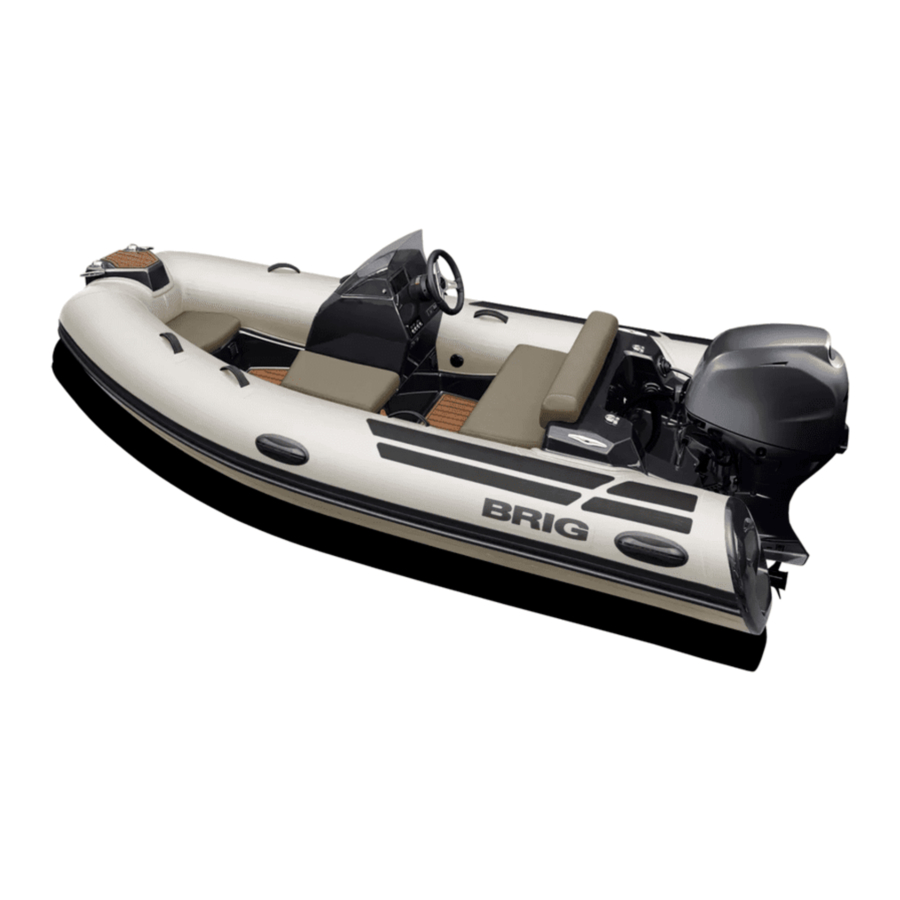
PRODUCT DESIGN


DESCRIPTION (See Fig.1) :
- Fiberglass plastic hull.
- Reinforced buoyancy tube.
- Rubbing strake.
- Towing bow eye.
- Front step plate.
- Navigation lights (red and green).
- Steering c onsole
- Steering wheel
- Masthead navigation light (white).
- Lifting eyes
- Front removable cushion.
- Safety handles.
- Hatch
- Side cursion.
- The neck of the fuel tank.
- Air fill valve
- Stern cushion with backrest.
- Rear mooring cleats.
- Handles.
- Bilge pump nozzle
- Cockpit drain sockets.
- Outlet for steering cable
- Drain plug
- Plate with HIN code
LOCATION OF THE MAIN SYSTEMS

See Fig. 2
- Bow locker
- Air fill valve
- The neck of the fuel tank
- Fuel level sensor
- Fuel tank (33L)
- Fuse box
- Stern hatch
- Main switch with fuse (port side)
- Battery
- Fitting of a fuel tank ventilation
- Cockpit drain sockets
- Cockpit drain hoses
- Cockpit drain valves
- Automatic bilge pump
BUOYANCY TUBE
The boat buoyancy tube has U-shaped form. The tube is separated by means of inner elastic partitions into 3 chambers of a similar volume, each being provided with an air fill valve.
The air fill valve is intended for:
- filling the compartment with air from a standart pump or filling system and maintaining pressure in the tube for prolonged time,
- adjustable drop of pressure in compartment.

The air fill valve is designed as a tab-type non-return valve and consists of the following components (Fig. 3):
- housing (1);
- cup (2) with strap (3);
- washer with gasket (4);
- nut (5);
- spindle (6) with spring (7) and cup diaphragm (8).
Also there are the following elements fitted on the tube (Fig. 1):
- doubled rubbing strake;
- safety handles;
- bow step-plate with navigation lights;
- tube polyester ends with two antiskid steps each.
The sequence of filling the pipe with air:
- Fill one of the compartments with air to a pressure of approximately 0.1 bar.
- Fill the other compartments sequentially with air to a pressure ofapproximately 0.1 bar(1.45psi).
- Only after that, bring the air pressure in each tube compartment to thenominal (0.15 bar/2.2psi).
 | Do not use compressors and/or other types of inflating equipments not approved by the boat builder. |
| Check the tube pressure before every navigation. | |
| The rated pressure value is 0.15 bar (2.2 psi). If the tube pressure more than nominal, deflate the tube slightly. Boat exploitation with board pressure more than nominal decreases boat service life. |
TUBE INFLATION
Before inflation of compartment it's necessary to set all valves in operating condition. In order to switch valve to operating condition, just press spindle 6 (look before Fig. D3) with your finger and turn it clockwise untill it is fixed. If it isn't possible the valve is in operating condition already.
Fill the tube compartments with air using the pump from the complete set. First fill two rear compartments, then bow compartment. Thereat, do not bring the pressure up to its operating value (the tube will be completely straightened).
Then fill the bow compartment with air up to the rated pressure.
The rated pressure value is 0.15 bar (2.2 psi)
On completion of filling close the valves with caps.
In order to discharge air from the compartments, open the valves (just press spindle with your finger and turn it anticlockwise till it is fixed).
| ATTENTION | Board air chambers are hermetical if they keep own form during 8 hours. In this case:
|
| Do not use compressors and/or other types of inflating equipments not approved by the boat builder. |
| Check the tube pressure before every navigation. | |
| The rated pressure value is 0.15 bar (2.2 psi). If the tube pressure more than nominal, deflate the tube slightly. Boat exploitation with board pressure more than nominal decreases boat service life. |
STEERING CONSOLE

Steering console is located in the central part of the boat. The console consists of the following components (Fig. 4):
- console body is installed on the built-in the boat deck console base;
- windscreen;
- instrument placement (speedometer, fuel gauge, chartplotter, etc.);
- hatch;
- steering wheel;
- switch panel;
- socket 12V + USB;
- fuse box (inside the body of the console, not shown);
SWITCH PANEL AND FUSE BOX

The purpose of the switches(Fig.5):
- turning on / off navigation lights (red and green)
- turning on / off anchor light (white all-round)
- turning on / off the bilge pump in automatic mode
- turning on / off the bilge pump in manual mode
Access to the fuse box - through the hatch on the console.
- fuse is used as a backup
- fuse is used for navigation lights
- fuse is used for anchor light
- fuse is used for the bilge pump
- fuse is used as a backup
- fuse is used for sockets 12V and USB
| Always check the fuse. Burning red LED display on the fuse box warns of faulty fuse |
| Always keep a spare set the fuse in an easily-accessible location. |
WIRING DIAGRAM

See Fig. 6
DESCRIPTION:
- Battery (provided on the market).
- Battery disconnector with fuse.
- Outboard motor (provided on the market).
- Bilge pump.
- Anchore light (white).
- Port light (red).
- Starboard light (green).
- Fuel level gauge.
- fuel gauge.
- Speedometer
- Tachometer
- Meter lamp and navigation lights switch with 5A safety device.
- Hull drain pump "MANUAL" / "AUTO" switch with 10A safety device.
- Anchore light switch with 5A safety device.
| ATTENTION | When leaving the boat, remember to disconnect the batteries. |
| Any modification, repair and planned maintenance may be made by authorized representative specialists only. |
| Do not touch the electrical equipment with wet hands. |
BATTERY INSTALLATION
In order to install the storage battery, perform next operations: — open door of the stern compartment; — install the storage battery into the battery container; — connect the battery terminals with motor battery cord and battery disconnector; — please, check efficiency of the electric equipment.
| Before installation your storage battery read the BATTERY MANUAL carefully and ensure that you have understood all the described procedures. |
FUEL SYSTEM

Fuel system consists of the following components (Fig. 7):
- built-in fuel tank 33L with level sensor
- fuel gauge
- fuel line (from fuel fill neck to fuel tank)
- fuel fill neck
- fuel tank ventilation line (5) with ventilation fitting (6)
- carbon canister (may not be installed by the manufacturer)
- fuel line to the engine
- fuel filter (not installed by the manufacturer)
- fuel level sensor
- inspection hatches
 | Check the fuel system before each use of the boat. No damage to the fuel hoses, tank and other components of the fuel system is allowed. |
| Pre-filter and fuel valve must be installed by authorized representative specialists only. |
| Do not modify fuel system. Any modification, repair and planned maintenance of the fuel system may be made by authorized representative specialists only. |
| Check that there are no leaks in the fuel systems |
| Do not smoke when refueling. Stop the engine and switch off any electric equipments before refueling. |
| It is dangerous to pretend to be an expert. This may cause damages. Refer to expert and authorized specialists for all types of maintenance and repair. |
DRAIN SYSTEM

Drain system, (Fig. 8), consists of the three independent systems:
- cockpit drain system;
- engine recess drain thru-hull;
- hull drain system.
COCKPIT AND ENGINE RECESS DRAIN SYSTEM:
- two cockpit drain sockets with waterproof plugs (1);
- two stern drain sockets with flexible diaphragmes (2);
- two drain hoses (3);
- engine recess drain thru-hull (4).
HULL DRAIN SYSTEM:
- automatic bilge pump (5);
- drain hose (6);
- bilge pump drain thru-hull mounted in the engine recess (7).
- bilge valve (8).
| Always the cockpit drain sockets must be open during navigation. Do not obstruct cockpit drain sockets at any time. Do not dispose bulky objects in front of the cockpit drain sockets. |
| Do not modify drain systems. Before navigation check the drain valves. | |
| Never locate heavy objects on the drain hoses. It will be cause of bucking, distortions and d am ag es. | |
| Bilge valve (8)(Fig.8) should be tightly CLOSED when the boat on the water Bilge valve (8)(Fig.8) should be open when the boat is out of the water |
| It is dangerous to pretend to be an expert. This may cause damages. Refer to expert and authorized specialists for all types of maintenance and repair. |
| Always the cockpit drain sockets must be open during navigation. Do not obstruct cockpit drain sockets at any time. Do not dispose bulky objects in front of the cockpit drain sockets. |
| Do not modify drain systems. Before navigation check the drain valves. Never locate heavy objects on the drain hoses. It will be cause of bucking, distortions and d am ag es. |
CREW LIMIT
On the picture (Fig.9) you can see the recommended location of the crew in the boat.
All persons should always use the handholds to avoid falling overboard. On Fig.9 you can see the location of the handholds for each crew member. Any part of the boat can be a handholds that can be grabbed by hand to reduce the risk of falling overboard. Example handholds: handle, shroud, seat edge, cleats, steering wheel.
Persons can be placed on the buoyancy tube. BUT in this case persons on the tube should always use two handholds at the same time so as not to fall overboard.

| | Periodically check the handholds. There should be no damage on the handholds and their fixation. |
| | Always check the correct and safe accommodation of all persons in the boat. |
| | Reduce speed when persons are sitting on the buoyancy tube. |
TOWING
There is U-bolt in the bow ((1) Fig.10) of your boat for towing.
On towing rope (2) should be a means (3) to quickly disconnect your boat from the tugboat.

| U-bolt for towing is designed for a maximum horizontal load of 8.2kN. The breaking strength of rope shall in general not exceed 80% of the breaking strength of the respective strong point. |
| Always check the U-bolts and their attachment points to the boat hull for damage. |
| Always have a towing rope on board |
MOORING

For mooring on the boat are installed (Fig 11):
- two bow cleats,
- bow U-bolt,
- two stern cleats.
Use bow cleats (1) only for mooring in calm water for a short time. If you are leaving the boat and there is a possibility of rough water or strong wind, use only bow U-bolt (2) to bow mooring.
Always use the rear cleats for mooring.
Do not use other parts or elements of the boat for mooring.
Make sure that the mooring rope does not damage the buoyancy tube or other elements of the boat.
Rope for mooring must be appropriate strength, diameter and length.
| U-bolts for mooring is designed for a maximum horizontal load of 6.8kN. Stern cleat for mooring is designed for a maximum horizontal load of 5.7kN. The breaking strength of rope shall in general not exceed 80% of the breaking strength of the respective strong point. |
| Be careful when mooring. Suddenly tensioned mooring ropes may cause injury. |
PRODUCT TRAILERING
When installing the boat on a trailer for transporting or storing the boat outside the water, the entire surface "Basic load area " should be in support (Fig.12).
It is allowed to use reference points indicated in the figure as (1), (2), (3), (4). Dimensions are in mm. Tolerances +/- 50mm
Other surfaces of the boat's body can only be auxiliary supporting it from capsizing.
To avoid damage to the hull of the boat, DO NOT install the boat only on the side area

THE MAIN DIMENSIONS
The main dimensions of Eagle 3.5 have tolerance of +/- 3%. All dimensions in meters.
The dimensions of the boat with the engine (parameters L1 and H3) can vary depending on the model of the engine and the angle of its deviation. (See Fig. 13)

| L1 (m) | L2 (m) | H1 (m) | H2 (m) | H3 (m) | B1(m) | |
| Eagle3.5 | 4.15 | 3.50 | 1.2 | 0.89 | 1.2 | 1.78 |
MAINTENANCE
- Main conditions of long service life is right and careful servicing. Avoid excessive increasing of pressure in the board, especially from heating by the sun rays.
- At the end of exploitation take off sand and dirt from boat surface, and carefully dry it.
- Avoid the water getting into the chambers. If a fuel or an oil gets to the boat surface it is necessary to wash the soiled place by soap water as soon as possible and dry.
- Pay attention to the condition of bottom surfaces. If the cover is destroyed it is necessary to dry this element and restore the defend cover.
- At the end of the season exploitation, prepare the boat to winter keeping. Clean boat surface from sand and dirt, and make the necessary repairs, if damages take place. If it is possible, keep the boat in open and slightly pumped state at air temperature 0-25°C. The boat must be protected from the sun rays.
- Insignificant boat repairing (eliminating the board punctures or cuts) you may carry out by yourself. In this case use the coated fabric and glue set for repair from the complete set.
The own fulfilment of any complex repair associated with considerable damages to the board, partitions and seams is not recommended.
In such cases, apply to your dealer.
| ATTENTION | Storage of the boat with temperature variations from -30°C to +45°C may be allowed not longer than 1 month. In case the boat has been stored or transported at a temperature below 0°C, it must be kept at a temperature above +15°C at least for 1 hour before to be unpacked and unfolded. |
| For small repair boat tube use the coated fabric and glue set from the complete set. |
OPERATING REGULATIONS
Dear user,
We thank your for your purchase and do hope that you will have a great fun of it. However, to make your joy and pleasure complete, we would request you to read carefully and observe the directions and recommendations specified below.
| | IT IS STRICTLY FORBIDDEN to handle the boat in the state of intoxication and without individual rescue means being used (life-saving belts, jackets, etc.) |
| IT IS FORBIDDEN to use an outboard motor of power exceeding the maximum allowable value | |
| | IT IS FORBIDDEN to bring the tube pressure up to the value exceeding the rated one (0.15 bar(2.2psi)) |
| IT IS STRICTLY FORBIDDEN to drag the boat across a rough surface. | |
| For each particular water area the local shipping regulations are in force. You may apply for information to the appropriate water transport and shipping directorate, as well as to the water police. | |
| | Use the boat equipment and accessories only on their direct purpose to ensure reliable service. |
| Even when sailing with an outboard engine you should always have the oars available with you so that you were able to reach the shore without outside assistance in case of any damage of the boat. | |
| | On your request any outboard engine seller may provide your engine with the emergency stop switch. During navigation the switch should be connected to the wrist of your hand by means of a cord. In case you fall overboard, even if being a steersman, the switch will cut out the engine and the propeller. This arrangement will enable you to avoid any traumas and to reach the boat. |
| Take all possible precautions against penetration of fuel, oil or electrolyte from the storage battery into the inflatable boat. If it does happen wash thoroughly the fouled spots with water. | |
| You should be always sure that the number of people on board never exceeds that specified in the owner's manual or on the builder's plate provided on the transom. |
| The boat will retain an adequate floatability and will not keel over only provided that the load is arranged reasonably. Therefore, do not accommodate all passengers on the same side of the boat. | |
| All passengers should be accommodated inside the boat. The occupied seats should not be left throughout the entire sailing time. |
| All passengers should put on life-saving jackets. |
| CHILDREN and non-swimmers MUST WEAR A FLOATATION DEVICE AT ALL TIMES. | |
| Always check that floatation devices for children are of the right size and that they are operation al. | |
| Arrange the cargo to be carried uniformly inside the boat, all items being reliable secured on the bottom of the boat. |
| When sailing with an outboard engine the steersman should shift his body forward in the course of acceleration to prevent the boat forebody from raising under the force of upthrust waves. | |
| Despite the strong shell of the boat we recommend carefully handle and operate with sharp and pricking objects which you have on board. It concerns, for example, a knife blade, fish-hook point, etc. |
| Approaching to rocky shores, shoals, moles, etc., please be careful to avoid damages of your boat. It is strictly prohibited to drag the boat across rough surfaces (shingle, rocks, concrete, etc.). |
| In case of prolonged navigation with the use of an outboard motor, regularly check, that the motor is reliably attached to the boat. If the engine was attached carelessly, the attachment may loosen under the action of vibration. | |
| Besides, at regular intervals, please check air chambers pressure, since the pressure may vary under the effects of outside air temperature and atmospheric pressure variations. |
| Never forget to monitor regularly the quantity of fuel in the fuel tank. Keep always in mind that the quantity of fuel should be sufficient for you to sail to your final destination. | |
| |
| ATTENTION | At towing the towing rope length should not be less at least 3 lengths of the boat. |
| The steersman of the towed boat should be assisted by another crew member to monitor the process of towing. In this case, certain communication gestures should be agreed upon beforehand. | |
| | The rope have to be attached to both boats in a manner ensuring its immediately, singlemotion release. |
| Damage to one of air chambers The inflatable boat is designed to provide an adequate stability in case of the complete damage to one of the air chambers (balloon compartments) at the expense of the remaining air chambers and the hull. Thanks to it, you will be able to reach safely the nearest shore. Reduce the speed and shift your body to the undamaged part of the boat. Observe changes in stability. After that, immediately head for the nearest shore. To prevent penetration of water into the boat, pull the shell of the damaged air chambers upwards. | |
| Mooring fast fastening | |
| Attach towing rope in the bow of the boat to the one of the frontal towing rings. Attach bow mooring ropes to the bow mooring cleats only. Attach rear mooring ropes or the rope of back anchor to the rear mooring cleats only. |
| Danger of currents and wind | |
| Before begin navigation on the boat, make detail inquiries about local conditions and regulations! Currents, wind, shoals, rising and falling tides, as well as weather variations may imply serious danger! |
| |
| |
| Manoeuvrability above 15knotes (25 km/h) is limited. Sudden turn may cause loss of control. Reduce speed before sharp turn, in either direction. |
| When the boat is fitted with an engine with maximum recommended power it must be use with extreme care. This application is directed at experienced users using their boats for very specific purposes. |
| Do not operate your boat with an engine of rated power larger than that stated on the builder's plate in the boat. |
| ATTENTION | Do not operate this craft at negative propulsion unit trim settings (bow down) at high speed. Craft may lean over on side. Instability in turns may result. Use negative trim to accelerate to planing speed from displacement speed and at lower planing speeds in choppy water (applicable to craft equipped with propulsion unit power trim). |
| ATTENTION | Do not operate at maximum speed while in congested high traffic waterways or in weather and sea conditions of reduced visibility high winds or large waves. Reduce speed and wake as a courtesy and as a safety consideration to yourself and others. Observe and obey speed limit and no wake zones. |
| ATTENTION | Observe right-of-way as defined by Rules of the Road and required by COLREG. |
| Always be certain to have sufficient distance to stop or manoeuvre if required to avoid c o llision s. | |
WARNING SIGNS AND LABELS
In accordance with ABYC standards, warning signs and labels are installed on your boat (if applicable).
Do not remove warning signs and labels. Always check their suitability.
If the warning signs are damaged and you cannot read the text or symbols, you must order new ones from your dealer.
Check with your dealer for the correct warning signs and labels mounting location.

BOAT CAPACITY LABEL.
Place of installation: on a boat transom
MAXIMUM ENGINE WEIGHT.
Place of installation: on the hull of the boat near the outboard engine.

LEAKING FUEL
Place of installation: on the hull near of the fuel filler.

ROTATING PROPELLER
Place of installation: from the outside of the boat transom.

FAILURE TO FOLLOW THESE WARNINGS COULD SEVERE INJURY OR DEATH
Place of installation: on the steering console.

NOTE: The inflatable boat was delivered with the following equipment installed:
| Stamp and signature |
| Stamp and signature |
| Stamp and signature |
| Stamp and signature |
| Stamp and signature |
| Stamp and signature |
| Stamp and signature |
SAFETY REGULATIONS
This manual contains recommendations and basic rules of conduct for using the boat in complete safety. Although it is not possible to offer safety information for all potential situations, in general it is recommended that you:
| | Regularly check which safety requirements are in force. |
| Maintain the boat and the onboard plants in optimum condition. | |
| Have the boat inspected by the dealer where it was purchased or by an authorised mechanic at least once every year for your own safety and for maintaining the guarantee. | |
| | Always check weather and seagoing conditions before setting out. For safe navigation, compare the design category of your boat with the table below. |
 When the tank is installed by the yard, the plant is prepared with a ground plait. The installation of the motor MUST FORESEE A PLAINT CONNECTION to the boat ground plait. Failure to connect (or failed maintenance) can result in the tank perforating leading to a serious risk of fire / explosion caused by leaking fuel. When the tank is installed by the yard, the plant is prepared with a ground plait. The installation of the motor MUST FORESEE A PLAINT CONNECTION to the boat ground plait. Failure to connect (or failed maintenance) can result in the tank perforating leading to a serious risk of fire / explosion caused by leaking fuel. | |
| | Max number of transportable persones is referred to an established weight of 75 kg per person (ISO 6185), so always make reference to total maximum transportable weight. The max weight of the installable motors indicates the maximum overall weight applicable on the stern board, including any emergency motors. NEVER exceed the stated value. |
BEAUFORT Wind Scale and Corresponding State of the Sea, After Few Hours of Wind, Away From the Coast.
| Force | Denomination | Knots | Km/h | m/sec | State of the sea and wave height in meters | |
| 0 | Calm | < 1 | < 1 | 0-0.2 | Calm | 0 |
| 1 | Light Air | 1-3 | 1-5 | 0.3-1.5 | Calm | 0 |
| 2 | Light Breeze | 4-6 | 6- 11 | 1.6-3.3 | Almost calm | 0.2 |
| 3 | Gentle Breeze | 7- 10 | 12-19 | 3.4-5.4 | Almost calm | 0.2 |
| 4 | Moderate Breeze | 11-16 | 20-28 | 5.5-7.9 | Small waves | 0.5 |
| 5 | Strong Breeze | 17-21 | 29-38 | 8.0-10.7 | Large waves | 1.25 |
| 6 | Fresh Wind | 22-27 | 39-49 | 10.8-13.8 | Large waves | 2.0 |
| 7 | Strong Wind | 28-33 | 50-61 | 13.9-17.1 | Very large waves | 2.5 |
| 8 | Gale | 34-40 | 62-74 | 17.2-20.7 | Rough sea | 4 |
| 9 | Strong Gale | 41-47 | 75-88 | 20.8-24.4 | Very rough sea | 6 |
| 10 | Storm | 48-55 | 89-102 | 24.5-28.4 | Heavy | 9 |
| 11 | Violent Storm | 56-63 | 103- 117 | 28.5-32.6 | Very heavy | 1 4 |
| 12 | Hurricane | 64 and over | 118 and over | 32.7 and over | Stormy | 14 and over |
Boat Design Categories (Directive 2013/53/EU):
| Design category | Wind force (Beaufort scale) | Significant wave height |
| exceeding 8 up to, and including, 8 up to, and including, 6 up to, and including, 4 | exceeding 4 up to, and including, 4 up to, and including, 2 up to, and including, 0.3 |
NOTE: The significant wave height is the mean height of the highest one-third of the waves, which approximately corresponds to the wave height estimated by an experienced observer. Some waves will be double this height.
ALWAYS REMEMBER ABOUT FIRE DANGER
Fire may be caused by:
Crew negligence when smoking, the presence aboard of flammable liquids, electrical contacts, propulsion motor, errors in fueling, or if maintenance has not been performed as required.
Once again, it is important that the crew behave correctly and that the boat is kept in order to avoid serious damage to it and to persons.
| Easily flammable products must not be kept aboard. |
| BATTERY: the battery may cause sparks or explosions. It must be stored in an appropriate container, easily reached and well aired, AWAY FROM FUEL OR INFLAMMABLE PRODUCTS. Periodically check that the clips are tight and protect them with appropriate insulation in order to prevent sparks or the spread of current. |
However, if a fire does occur aboard, stop motor, disconnect the batteries immediately, check to see if it is an electrical component or any case a small-scale fire that does not involve flammable liquids, in which case use a suitable fire extinguisher to try and put the fire out completely.
| | Extinguisher or any other fire-fighting equipment must not be kept in compartments with key lock, but in easily accessible and clearly indicated locations. |
| Extinguisher or any other fire-fighting equipment should be checked periodically and replaced with the same or superior types if expired or inefficient. | |
| | Equip the boat with fire-fighting equipment before launch and use. |
For you safety and for the validity of the guarantee expert and authorised personnel must install the motor and inspect and check the systems. All onboard systems must be completed and inspected.
CHECK, THAT THE CHECKS HAVE BEEN MADE AND THAT THE PLANTS HAVE BEEN COMPLETED BEFORE DELIVERY.
BRIG Ltd declines any responsibility for systems and accessories that hav e not been installed and checked by expert and authorised personnel.
The manual and all its enclosures should be stored carefully, and the manual should always be kept aboard. If the craft is resold, the manual and all its enclosures must be handed over to the new owner.
DANGER LEVELS
The manual contains warnings, identified as follows:
| A note like this indicates that there is serious risk, that is likely to cause death or permanent serious injury, if appropriate precautions are not taken. |
| A note like this indicates the existence of risk that may cause death or injury, if appropriate precautions are not taken. |
| ATTENTION | A note like this indicates reference to the application of safety or environmental protection practices, or draws attention to unsafe behaviour that might cause injury to persones or damage to the craft, its components or the environment. |
Documents / ResourcesDownload manual
Here you can download full pdf version of manual, it may contain additional safety instructions, warranty information, FCC rules, etc.
Download Brig Eagle 3.5, E3.5, E3.5H - Eagle Series Boats Manual
Advertisement


Need help?
Do you have a question about the Eagle Series and is the answer not in the manual?
Questions and answers