BRIG EAGLE Series Owner's Manual
Hide thumbs
Also See for EAGLE Series:
- User manual ,
- Owner's manual (36 pages) ,
- Owner's manual (36 pages)

Related Manuals for BRIG EAGLE Series


Summary of Contents for BRIG EAGLE Series
- Page 1 OWNER'S MANUAL English "EAGLE" SERIE: Eagle 3.5 MODEL: complete set: E3.5 E3.5H* Design category (2013/53/EU): ISO6185: Category VII H* – boat tube is made of HYPALON (Du Pont registered trademark) coated fabrics.
-
Page 2: Table Of Contents
TUBE INFLATION STEERING CONSOLE SW ITCH PANEL AND FUSE BOX W IRING DIAGRAM BATTERY INSTALLATION FUEL SYSTEM DRAIN SYSTEM CREW LIMIT TOWING MOORING BOAT TRAILERING THE MAINE DIMENSIONS MAINTENANCE OPERATING REGULATIONS W ARNING SIGNS AND LABELS — 2 — BRIG... - Page 3 CHECK, THAT THE CHECKS HAVE BEEN MADE AND THAT THE PLANTS HAVE BEEN COMPLETED BEFORE DELYVERY. BRIG Ltd declines any responsibility for systems and accessories that hav e not been installed and checked by expert and authorised personnel. The manual and all its enclosures should be stored carefully, and the manual should always be kept aboard.
- Page 4 The CE marking indicates that the inflatable boat meets the requirements of the Recreational Craft Directive 2013/53/EU Certifying Body: INTERNATIONAL MARINE CERTIFICATION INSTITUTE Rue Abbe Cuypers 3 / B-1040Bruxelles / Belgique Notified Body : 0609 www.imci.org Name of Manufacture: BRIG Ltd. Lozovskaya 88, Dergachy 62303 Kharkovskaya obl. UKRAINE www.brigboats.com — 4 — BRIG...
-
Page 5: Danger Levels
DANGER LEVELS. The manual contains warnings, identified as follows: A note like this indicates that there is serious risk, that is likely to cause death or permanent serious injury, if appropriate precautions are not taken. A note like this indicates the existence of risk that may cause death or injury, if appropriate precautions are not taken. -
Page 6: Identification Plate
W ithout them the boat does not comply with the legislation in effect. The plates must never be removed. Any tampering or removal not authorised by the manufacturer is the full responsibility of the owner. — 6 — BRIG... -
Page 7: Safety Regulations
SAFETY REGULATIONS. This manual contains recommendations and basic rules of conduct for using the boat in complete safet y.Although it is not possible to offer safety information for all potential situations, in general it is recomm ended that you : Regularly check which safety requirements are in force. -
Page 8: Beaufort W Ind Scale
0.3 NOTE: The significant wave height is the mean height of the highest one-third of the waves, which approximately corresponds to the wave height estimated by an experienced observer. Some waves will be double this height. — 8 — BRIG... - Page 9 ALWAYS REMEMBER ABOUT FIRE DANGER. Fire may be caused by: Crew negligence when smoking, the presence aboard of flammable liquids, electrical contacts, propulsion motor, errors in fueling, or if maintenance has not been performed as required. Once again, it is important that the crew behave correctly and that the boat is kept in order to avoid serious damage to it and to persons. Easily flammable products must not be kept aboard.
- Page 10 Loaded displacement mass * W hen the boat is fitted with an engine with maximum recommended power it must be use with extreme care. This application is directed at experienced users using their boats for very specific purposes. — 10 — BRIG...
-
Page 11: Complete Set 1
COMPLETE SET. In the table shows the maximum possible complete set, which may differ from your boat. Des c ri p t io n Unit Eagle 3.5 Rigid inflatable boat pc . Foot pump pc . Pa dd l e p c s . -
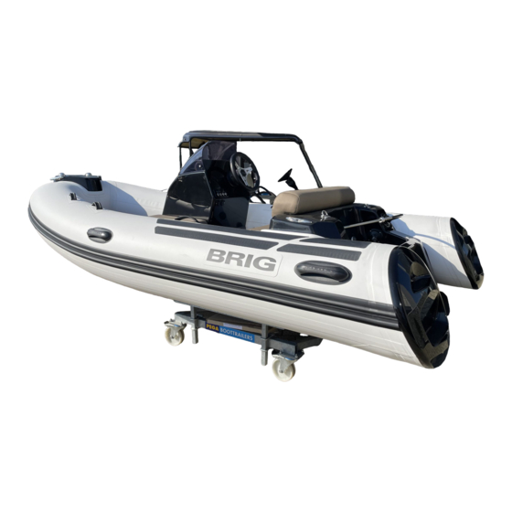
Page 12: Boat Design 1
BOAT DESIGN. Fig.1 — 12 — BRIG... - Page 13 DESCRIPTION: 1 — Fiberglass plastic hull. 2 — Reinforced buoyancy tube. 3 — Rubbing strake. 4 — Towing bow eye. 5 — Front step plate. 6 — Navigation lights (red and green). 7 — Steering c onsole 8 — Steering wheel 9 —...
-
Page 14: Location Of The Main Systems
1 1 — Cockpit drain sockets 5 — Fuel tank (33L) 1 2 — Cockpit drain hoses 6 — Fuse box 1 3 — Cockpit drain valves 7 — Stern hatch 1 4 — Automatic bilge pump Fig.2 — 14 — BRIG... -
Page 15: Buoyancy Tube 1
BUOYANCY TUBE. The boat buoyancy tube has U-shaped form. The tube is separated by means of inner elastic partitions into 3 chambers of a similar volume, each being provided with an air fill valve. The air fill valve is intended for: —... -
Page 16: Tube Inflation 1
Check the tube pressure before every navigation. The rated pressure value is 0.15 bar (2.2 psi). If the tube pressure more than nominal, deflate the tube slightly. Boat exploitation with board pressure more than nominal decreases boat service life. — 16 — BRIG... -
Page 17: Steering Console 1
STEERING CONSOLE. Steering console is located in the central part of the boat. The console consists of the following components (Fig. 4): — console body (1) is installed on the built-in the boat deck console base — windscreen (2); — instrument placement (3) (speedometer, fuel gauge, chartplotter, etc.); —... -
Page 18: Switch Panel And Fuse Box
6 - fuse is used for sockets 12V and USB FUSE BOX Always check the fuse. Burning red LED display on the fuse box warns of faulty fuse Always keep a spare set the 2336.13 fuse in an easily-accessible location. Fig.5 — 18 — BRIG... -
Page 19: Wiring Diagram
WIRING DIAGRAM. fuel tank bow plate steering console Fig.6 stern locker DESCRIPTION: — Battery (provided on the market). — Battery disconnector with fuse. W hen leaving the boat, remember — Outboard motor (provided on the market). to disconnect the batteries. —... -
Page 20: Battery Installation
– carbon canister (7) (may not be installed by the manufacturer) – fuel line to the engine (8) – fuel filter (9) (not installed by the manufacturer) – fuel level sensor (10) – inspection hatches (11) Fig.7 — 20 — BRIG... - Page 21 Check the fuel system before each use of the boat. No damage to the fuel hoses, tank and other components of the fuel system is allowed. Pre-filter and fuel valve must be installed by authorized representative specialists only. Do not modify fuel system. Any modification, repair and planned maintenance of the fuel system may be made by authorized representative specialists only.
-
Page 22: Drain System 2
– two drain hoses (3); – engine recess drain thru-hull (4). HULL DRAIN SYSTEM : – automatic bilge pump (5); – drain hose (6); – bilge pump drain thru-hull mounted in the engine recess (7). – bilge valve (8). Fig.8 — 22 — BRIG... - Page 23 Always the cockpit drain sockets must be open during navigation. Do not obstruct cockpit drain sockets at any time. Do not dispose bulky objects in front of the cockpit drain sockets. Do not modify drain systems. Before navigation check the drain valves. Never locate heavy objects on the drain hoses.
-
Page 24: Crew Limit 2
Always check the correct and s afe ac commodation of all persons in the boat. Reduce speed when persons are sitting on the buoyancy tube. Fig.9 — 24 — BRIG... -
Page 25: Towing 2
TOWING. There is U-bolt in the bow ((1) Fig.10) of your boat for towing. On towing rope (2) should be a means (3) to quickly disconnect your boat from the tugboat. U-bolt for towing is designed for a maximum horizontal load of 8.2kN. The breaking strength of rope shall in general not exceed 80 % of the breaking strength of the respective strong point. -
Page 26: Mooring 2
Suddenly tensioned mooring ropes may cause maximum horizontal load of 5.7kN. injury. The breaking strength of rope shall in general not exceed 80 % of the breaking strength of the respective strong point. Fig.11 — 26 — BRIG... -
Page 27: Boat Trailering 2
BOAT TRAILERING. W hen installing the boat on a trailer for transporting or storing the boat outside the water, the entire surface "Basic load area " should be in support (Fig.12). It is allowed to use reference points indicated in the figure as (1), (2), (3), (4). Dimensions are in mm. Tolerances +/- 50mm Other surfaces of the boat’s body can only be auxiliary supporting it from capsizing. -
Page 28: The Maine Dimensions 2
The dimensions of the boat with the engine (parameters L1 and H3) can vary depending on the model of the engine and the angle of its deviation. (See Fig. 13) L1 (m) L2 (m) H1 (m) H2 (m) H3 (m) B1(m) Eagle3.5 4.15 3.50 0.89 1.78 Fig.13 — 28 — BRIG... -
Page 29: Maintenance 2
MAINTENANCE. Main conditions of long service life is right and careful servicing. Avoid excessive increasing of p ressure in the board, especially from heating by the sun rays. At the end of exploitation take off sand and dirt from boat surface, and carefully dry it. ... -
Page 30: Operating Regulations 3
This arrangement will enable you to avoid any traumas and to reach the boat. Take all possible precautions against penetration of fuel, oil or electrolyte from the storage battery into the inflatable boat. If it does happen wash thoroughly the fouled spots with water. — 30 — BRIG... - Page 31 You should be always sure that the number of people on board never exceeds that specified in the owner's manual or on the builder's plate provided on the transom. The boat will retain an adequate floatability and will not keel over only provided that the load is arranged reasonably.
- Page 32 Reduce the speed and shift your body to the undamaged part of the boat. Observe changes in stability. After that, immediately head for the nearest shore. To prevent penetration of water into the boat, pull the shell of the damaged air chambers upwards. — 32 — BRIG...
- Page 33 Mooring fast fastening Attach towing rope in the bow of the boat to the one of the frontal towing rings. Attach bow mooring ropes to the bow mooring cleats only. Attach rear mooring ropes or the rope of back anchor to the rear mooring cleats only.
- Page 34 Observe right-of-way as defined by Rules of the Road and required by COLREG. Always be certain to have sufficient distance to stop or manoeuvre if required to avoid c o llision s. — 34 — BRIG...
-
Page 35: W Arning Signs And Labels 3
WARNING SIGNS AND LABELS. In accordance with ABYC standards, warning signs and labels are installed on your boat (if applicable). Do not remove warning signs and labels. Always check their suitability. If the warning signs are damaged and you cannot read the text or symbols, you must order new ones from your dealer. Check with your dealer for the correct warning signs and labels mounting location. - Page 36 SEVERE INJURY or DEATH WARNING. ROTATING PROPELLER Place of installation: from the outside of the boat transom. W ARNING. FAILURE TO FOLLOW THESE W ARNINGS COULD SEVERE INJURY OR DEATH Place of installation: on the steering console. — 36 — BRIG...
- Page 37 NOTE: The inflatable boat was delivered with the following equipment installed: Stamp and signature 1.Fuel tank 5.Steering system Stamp and signature Stamp and signature 2.Electric system 6.Engine power system Stamp and signature 7.Engine installation, test and Stamp and signature 3.Drain system Stamp and signature c om pletio n plan tsan d...
- Page 38 Eagle 3.5 MODEL UA-QRK SERIAL No. Date of manufacture Quality inspection stamp...
Need help?
Do you have a question about the EAGLE Series and is the answer not in the manual?
Questions and answers