
Related Manuals for ADLINK Technology Nu-Step DA Series


Summary of Contents for ADLINK Technology Nu-Step DA Series
- Page 1 Nu-Step DA Series Stepper Drivers User’s Manual Stepper Driver Based on EtherCAT Field Bus Manual Rev.: Revision Date: June 7, 2023 Part Number: 50M-40802-1000...
- Page 2 Preface Copyright Copyright © 2023 ADLINK Technology, Inc. This document contains proprietary information protected by copyright. All rights are reserved. No part of this manual may be reproduced by any mechanical, electronic, or other means in any form without prior written permission of the manufacturer.
-
Page 3: Table Of Contents
Nu-Step DA Series Table of Contents Preface ..........................ii Table of Contents ......................iii List of Figures ........................iv List of Tables ........................v Introduction ........................ 1 1.1. Definitions and Abbreviation ..................2 1.2. Specifications ......................2 1.3. EtherCAT Field Bus Support and Tool Program ............4 1.4. -
Page 4: List Of Figures
List of Figures Figure 1: Application architecture of Nu-Step DA Series .................1 Figure 2: Nu-Step Series Mechanical Dimensions ...................5 Figure 3: Nu-Step Series Connector, Switch and LED Locations ............7 Figure 4: Homing Function ........................34 Figure 5: Zero return on negative limit switch and index pulse ..............35 Figure 6: Zero return on positive limit switch and index pulse ...............35... -
Page 5: List Of Tables
Nu-Step DA Series List of Tables Table 1: Dial Switch S1 Pin Definition ......................8 Table 2: IO Connector, IOIF1 Pin Definition .....................9 Table 3: Motor Drive Output Connector, J2 Pin Definition ..............10 Table 4: Driver Power Input Connector, J1 Pin Definition ..............11 Table 5: EtherCAT Connector, CN 1/CN2 Pin Definition ...............12... - Page 6 This page intentionally left blank. Preface...
-
Page 7: Introduction
Nu-Step DA Series 1. Introduction The ADLINK Nu-Step DA Series is a stepper driver based on the EtherCAT bus featuring a 32-bit ARM processor and advanced variable current and frequency conversion technology. The driver generates less heat and motor vibration for more stable operation. It not only supports the standard EtherCAT specification, but also supports table comparison triggers for automated optical inspection (AOI) and linear comparison triggers for line scanning. -
Page 8: Definitions And Abbreviation
1.1. Definitions and Abbreviation Controller Area Network CAN in Automation Communication Object (CAN message). A unit of transportation in a CAN network. Data must be sent across a network inside a COB. COB-ID COB-Identifier. Identifies a COB uniquely in a network. The identifier determines the priority of that COB in the MAC sublayer. -
Page 9: Environmental Specifications
Nu-Step DA Series 1.2.2. Closed-Loop Stepper Driver Specifications Model DA2D530EC DA2D542EC DA2D580EC Output Current 0.2-3.0A 1.0-4.2A 2.4-8.0A Input Voltage 15-50V DC Weight 0.2 kg Size 116 x 69.2 x 26.5 mm Interface Type Single-ended Control Protocol EtherCAT Operation Mode CSP / PP/ PV/ HM... -
Page 10: Ethercat Field Bus Support And Tool Program
Creator Pro 2 cannot only effectively shorten the development time, but also verify the whole mechanical and electrical design simultaneously through all single-axis and interpolation motion operation pages. 1.4. Model Nomenclature For Nu-Step DA Series model designation, refer to the following information. For example, model DA2D530EC can be interpreted as: Description Example... -
Page 11: Getting Started
Hardware Installation 2.3.1. Hardware Configuration The Nu-Step DA Series of stepper drivers conform to the standard EtherCAT field bus and CIA-402 protocol specifications. The upper controller can run different control modes for stepper motor behavior control and digital IO control. -
Page 12: Installation Procedures
2.3.2. Installation Procedures Read this manual carefully and set the digital input and output ports and power supply to the correct modes. The installation of multi-actuators must be kept above 30 mm to avoid the problems of poor heat dissipation and excessive EMI interference. -
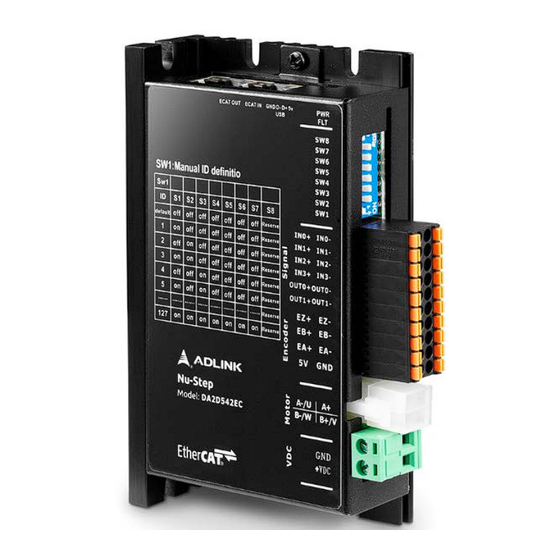
Page 13: Connector, Switch And Led Locations
2.4. Connector, Switch and LED Locations This section describes the Nu-Step DA Series connectors and their pinouts, and the LEDs and switches that are used on the module. IOIF1 115.5... -
Page 14: Table 1: Dial Switch S1 Pin Definition
2.4.1. Dial Switch, S1 Pin Orientation Pin Assignment 0 (default) Reserved Reserved Reserved Reserved Reserved Reserved …… …… …… …… …… …… …… …… Reserved Reserved Table 1: Dial Switch S1 Pin Definition The default exit value is ID=0. At this time, the EtherCAT slave ID of the driver is software ID, and the valid range of hardware ID is 1-127 2.4.2. -
Page 15: Table 2: Io Connector, Ioif1 Pin Definition
Nu-Step DA Series Pin Assignment Foot Definition Functional Description Position Number DI0- Digital input signal 0 negative terminal, differential mode, compatible level 5-24V DC DI0+ Digital input signal 0 positive terminal, differential mode, compatible level 5-24V DC DI1- Digital input signal 1 negative terminal, differential mode,... -
Page 16: Table 3: Motor Drive Output Connector, J2 Pin Definition
Notes: • Shielded cable is recommended for digital input and output wire, with wire diameter >0.12 mm , AWG 24-26. • Multi-core twisted pair shielded cable is recommended for encoder wire, with wire diameter >0.08 mm AWG 24-28. • Single-core wire is recommended for +5V DC power supply, with wire diameter >0.12 mm , AWG 22-26. -
Page 17: Table 4: Driver Power Input Connector, J1 Pin Definition
Nu-Step DA Series 2.4.4. Driver Power Input Connector, J1 Pin Orientation Pin Assignment Pin No. Signal Functional Description +DC in Positive electrode of DC power supply. Power supply Module power input voltage range: DC 15-50V DC, according to different power requirements of each machine type. Refer to 1.2.1 and 1.2.2 (24V DC or 36V DC recommended). -
Page 18: Table 5: Ethercat Connector, Cn 1/Cn2 Pin Definition
2.4.5. EtherCAT Connector, CN 1/CN2 Pin Assignment Pin No. Signal Functional Description EtherCAT data transmission positive terminal EtherCAT IN/OUT EtherCAT data transmission negative terminal EtherCAT data receiving positive terminal Not connected Not connected EtherCAT data receiving negative terminal Not connected Not connected Table 5: EtherCAT Connector, CN 1/CN2 Pin Definition It is recommended to use CAT5e standard wire with isolation and shielded joints at both ends, and it is... -
Page 19: Signal Connection
Nu-Step DA Series 3. Signal Connection The Nu-Step DA Series of stepper drivers offer 4-point digital inputs and 2-point digital outputs for use with standard EtherCAT upper motion controllers such as the PCIE-833x, Talos, TWINCAT and CODESYS. It also provides programmable function selection, so that users can set the stepper driver more easily. - Page 20 3.1.3. Input Function Setting Mode Use OD 0x2152 to select functions. OD Address Function Default Value Function Options Input Range 0: negative limit 1: positive limit DI0 function settings 2: zero 3: emergency stop 0: negative limit 1: positive limit DI1 function settings 2: zero 3: emergency stop...
-
Page 21: Universal Digital Output/Alarm/In-Position Signal
Nu-Step DA Series 3.2. Universal Digital Output/Alarm/In-Position Signal 3.2.1. Interface Circuit 3.2.2. Interface Circuit Specification Digital Output Specification Type Single-ended Voltage 5-24V DC Current < 100mA/Chs, pull-up resistance 2k ohm Channels Fastest COS frequency 1KHz 3.2.3. Output Function Setting Mode Use OD 0x2005 to select functions. -
Page 22: Comparison Trigger Signals
Error code When an error occurs in motion control, the error code is displayed. 3.3. Comparison Trigger Signals The Nu-Step DA Series of stepper drivers supports the comparison trigger functions often used in electronic assembly manufacturing industry. They can be used for in-line scanning or triggering image taking used in AOI equipment. - Page 23 Nu-Step DA Series 3.3.2. Interface Circuit Specification Digital Output Specification Type Single-ended Voltage 5-24V DC Current > 100mA/ Chs, Pull-up resistance 2k ohm Channels Fastest comparison trigger output frequency 1KHz 3.3.3. Output Function Setting Mode Use OD 0x2005 to select functions.
- Page 24 3.3.5. Point Table Comparison Trigger Output Corresponds to OD Address Default OD Address Function Function Options Input Range Value 0: disable Comparison trigger start 1: LCMP enable 0,1,2 2: TCMP enable When DO is set to CMP, the polarity when not triggered Default polarity 0: Normal Open...
-
Page 25: Encoder Input Signal
3.4. Encoder Input Signal The Nu-Step DA Series of stepper drivers include open-loop and closed-loop products. When using closed-loop products, users need to input encoders into the drivers. Because of encoder feedback, the common out-of-step problem of traditional stepper motors can be avoided. See the following table for the corresponding pins of feedback signal input of Nu-Step DA Series of encoders. - Page 26 This page intentionally left blank. Signal Connection...
-
Page 27: Motion Control
Nu-Step DA Series 4. Motion Control This chapter describes the EtherCAT motion control function supported by the slave station of Nu-Step DA Series of stepper drivers, as well as the OD used and precautions. In the EtherCAT specification, OD partitions are described as in the following table. - Page 28 Data Index Sub-Index Description Data Type Store Parameters UNSIGNED32 Save All parameters UNSIGNED32 0x1010 Save Communication Parameters UNSIGNED32 Save Application Parameters UNSIGNED32 Save Manufacturer Parameters UNSIGNED32 Restore Parameters UNSIGNED32 Restore All Default Parameters UNSIGNED32 0x1011 Restore Communication Default Parameters UNSIGNED32 Restore Application Default Parameters UNSIGNED32 Restore Manufacturer Default Parameters...
- Page 29 Nu-Step DA Series Data Index Sub-Index Description Data Type SM2(Outputs) SyncManager Parameter Synchronization Type Cycle Time Shift Time Sync Types Supported 0x1C32 Minimum Cycle Time Calc and Copy Time Minimum Delay Get Cycle Time Minimum Hardware Delay Sync Cycle Time...
- Page 30 Data Index Sub-Index Description Data Type 0x2036 position loop Ki UINT 0x2037 position loop Kd UINT 0x2038 position loop Kvff UINT 0x2049 Motor rigidity UINT 0x2051 Polarity UINT 0x2071 Encoder Direction UINT 0x2150 Slave Alias UINT 0x2151 Slave Alias Source UINT Inputs Function DI0 Function...
- Page 31 Nu-Step DA Series Data Index Sub-Index Description Data Type CMP_POS DINT POS1 DINT POS2 DINT POS3 DINT POS4 DINT POS5 DINT POS6 DINT POS7 DINT 0x2166 POS8 DINT POS9 DINT POS10 DINT POS11 DINT POS12 DINT POS13 DINT POS14 DINT...
- Page 32 Data Index Sub-Index Description Data Type 0x6081 Profile Target Velocity UDINT 0x6082 End Velocity UDINT 0x6083 Profile Target Acceleration UDINT 0x6084 Profile Target Deceleration UDINT 0x6085 Quick Stop Deceleration UDINT 0x6098 Homing Method SINT Homing Velocity 0x6099 Homing velocity(fast) Homing velocity(slow) 0x609A Homing Acceleration UDINT...
- Page 33 Nu-Step DA Series Default OD Address Function Function Options Input Range Value DO function settings 1: Alarm 2: In-position DO0 function settings 3: CMP 0x2005 4: Master control 1: Alarm 2: In-position DO1 function settings 3: CMP 4: Master control...
- Page 34 Default OD Address Function Function Options Input Range Value DI function settings 0: negative limit 1: positive limit DI0 function settings 2: zero 3: emergency stop 0: negative limit 1: positive limit DI1 function settings 2: zero 3: emergency stop 0x2152 0: negative limit 1: positive limit...
- Page 35 Nu-Step DA Series Default OD Address Function Function Options Input Range Value Point table comparison trigger position Point table comparison 1000 #1 TCMP comparison trigger point -2^31-2^31-1 trigger position 1 Point table comparison 2000 #2 TCMP comparison trigger point -2^31-2^31-1...
- Page 36 4.1.2.2. Adjustment Function This function is effective for closed-loop motors. OD Address Function Default Value Function Options Input Range Automatically setting current loop PI when power on: Automatic adjustment 0x2013 0: No automatic adjustment takes effect 1: Automatic adjustment after enabling Current loop 0x2015 1000...
-
Page 37: Operation Mode
Nu-Step DA Series 4.1.2.4. Digital Input Uses Digital Filtering Function OD Address Function Default Value Function Options Input Range 0 DI digital filtering time 1 DI0 digital filtering time 1 - 32768, 1=50μs, digital filtering 1-32767 2 DI1 digital filtering time 1 - 32768, 1=50μs, digital filtering... - Page 38 Serial Number Object Dictionary Description Set Value Unit 6060H Operation mode None 6040H Control word Set as needed None 607AH Target location Set as needed Unit 6081H Protocol speed in location mode Set as needed Unit/S 6082H Take-off speed and stop speed in position mode Set as needed Unit/S 6083H Protocol acceleration...
- Page 39 Nu-Step DA Series 4.2.3. Cyclic Synchronous Position Mode (CSP mode) In this mode, the upper controller needs to have the profile planning function, and only needs to input the target position. Then the position command can be transmitted to the driver in a cyclic synchronous way.
-
Page 40: Homing Mode
Most modes also use the index pulse (zero) of the incremental encoder. Since the Nu-Step DA Series of stepper drivers do not support EZ signals, they only support zero return mode, with the exception of 33 and 34. -
Page 41: Figure 5: Zero Return On Negative Limit Switch And Index Pulse
Nu-Step DA Series 4.3.1. Zero Return Mode This section describes the details of how each zero return mode works. 4.3.1.1. Mode 1: zero return on negative limit switch and index pulse If the negative limit switch is not activated, the initial direction of motion will be left when using this mode. The starting position is at the first index pulse to the right of the position where the negative limit switch becomes invalid. -
Page 42: Figure 7: Zero Return On Positive Home Switch And Index Pulse
4.3.1.3. Modes 3 and 4: zero return on positive home switch and index pulse With modes 3 or 4, the initial direction of motion depends on the state of the home switch. The home position is at the index pulse to the left or right of the point where the home switch changes state. If the initial position is positioned so that the direction of motion must be reversed during the return to zero, the point at which the reversal occurs will be anywhere after the home switch state has changed. -
Page 43: Figure 9: Homing On The Home Switch And Index Pulse - Positive Initial Move
Nu-Step DA Series 4.3.1.5. Modes 7 to 14: zero return on home switch and index pulse These modes use a home switch, which only works on the part of the stroke and, in effect, has an "instantaneous" effect when the position of the axle sweeps across the switch. -
Page 44: Figure 11: Homing On The Positive Home Switch
4.3.1.7. Modes 17 to 30: zero return without index pulse These modes are similar to modes 1 to 14 except that the original position does not depend on the index pulse, but only on the associated original or limit switch transition. For example, modes 19 and 20 are similar to modes 3 and 4 shown in the following figure. -
Page 45: Comparison Trigger Mode
4.4. Comparison Trigger Mode The Nu-Step DA Series of stepper drivers supports the standard EtherCAT protocol and adds the comparison trigger function commonly used in equipment, so customers can easily apply this function to AOI detection triggered by camera image acquisition or module data acquisition. The OD used in the comparison trigger does not support PDO input, and the trigger frequency is up to 1KHz. -
Page 46: Error Code
4.4.2. How to Use Linear Comparison Trigger LCMP 1. Input appropriate parameters 0x2164.2-0x2164.5 and 0x2165.1 for comparison trigger. 2. Input parameters 0x2165.2 and 0x2165.3 required for the corresponding comparison trigger. 3. Input 0x2164.1=1 after confirming the above two points of data to complete the input. 4. -
Page 47: Safety Instructions
Nu-Step DA Series Safety Instructions Read and follow all instructions marked on the product and in the documentation before you operate your system. Retain all safety and operating instructions for future use. • Please read these safety instructions carefully. •... -
Page 48: Getting Service
San Jose, CA 95119-1208, USA Tel: +1-408-360-0200 Toll Free: +1-800-966-5200 (USA only) Fax: +1-408-600-1189 Email: info@adlinktech.com ADLINK Technology (China) Co., Ltd. 300 Fang Chun Rd., Zhangjiang Hi-Tech Park, Pudong New Area Shanghai, 201203 China Tel: +86-21-5132-8988 Fax: +86-21-5132-3588 Email: market@adlinktech.com ADLINK Technology GmbH Hans-Thoma-Straße 11...
Need help?
Do you have a question about the Nu-Step DA Series and is the answer not in the manual?
Questions and answers