Table of Contents
Advertisement
Quick Links
Advertisement
Table of Contents

Related Manuals for ADLINK Technology ND-6021


Summary of Contents for ADLINK Technology ND-6021
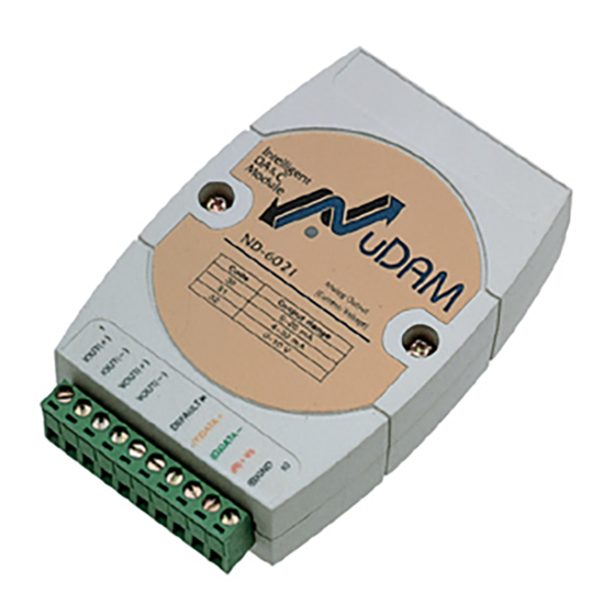
- Page 1 ND-6021 ND-6024 Analog Input Modules User’s Guide...
- Page 2 Trademarks NuDAM is registered trademarks of ADLink Technology Inc., Other product names mentioned herein are used for identification purposes only and may be trademarks and/or registered trademarks of their respective...
-
Page 3: Table Of Contents
Contents INTRODUCTION....................1-1 1. 1. DAM A BOUT THE NALOG UTPUT ODULES 1. 2. DAM-6021 VERVIEW OF 1. 3. DAM-6024 VERVIEW OF INITIALIZATION & INSTALLATION............2-1 2. 1. OFTWARE NSTALLATION 2. 2. NITIALIZING A RAND ODULE 2. 3. NSTALL A TO A XISTING ETWORK 2. - Page 4 3. 21. R & S 3-31 ATCHDOG IMER AFETY ALUE 3. 22. H 3-33 OST IS DATA FORMAT ..................... 4-1 4. 1. ONVERSION 4. 2. NGINEERING NITS 4. 3. ERCENT OF 4. 4. EXDECIMAL ORMAT 4. 5. UMMARY OF ORMAT ANALOG OUTPUT CALIBRATION............
-
Page 5: Introduction
1. 2. Overview of NuDAM-6021 What is NuDAM-6021 ? ND-6021 is an analog signal output module. It receives the digital command from host computer through RS-485 network. The format of the digital value can be engineering units, hexdecimal format or percentage of full-scale range(FSR). - Page 6 The analog output can be readback through the module‘s ADC. which can monitor the ’real‘ output of the device. The host can check the digital command and the real output to avoid short circuits. The slew rate of the output signal is also controllable by software. Features of NuDAM-6021 •...
- Page 7 Host programmable watchdog : 100 ms ~ 25.500 sec ² Power • Power supply : +10V to +30V • Power consumption : 1.0W Pin Definitions of ND-6021 Pin # Signal Name Description +IOUT Positive Current Output Terminal -IOUT Negative Current OutputTerminal...
- Page 8 A Look at ND-6021 & Pin Assignment Analog Output (Current/Voltage) ND-6021 Code Output Range 0 ~20 mA 4 ~ 20 mA 0 ~ 10V 1-4 Initialization & Installation...
-
Page 9: Overview Of Nudam-6024
Functional Block Diagram of ND-6021 Voltage Output Data+ Micro RS-485 VOUT + Processor Rec/DRv (12 bits) VOUT - Photo Isolators Data- RS-485 IOUT + V to I Terminator EEPROM IOUT - Current Output *Defalut Setting Watchdog / Power Failure (1 bit Digital In) - Page 10 Another safety fucntion is the watchdog. Whenever the host is loss contact with the remoted NuDAM module, or the micro-processor is down, the module will reset itself and send the safety value to the analog output therefore the industry safety is guarantee. The safety value / power-up value can be set by configuration software.
- Page 11 Pin Definitions of ND-6024 Pin # Signal Name Description Digital input channel 4 Digital input channel 3 Digital input channel 2 Digital input channel 1 Digital input channel 0 Default* Initial state setting (Y) DATA+ RS-485 series signal, positive (G) DATA- RS-485 series signal, negative (R) +Vs Power supply, +10V~+30V...
- Page 12 A Look at ND-6024 & Pin Assignment ND-6024 4-CH Analog Output Code Signal ±10V 1-8 Initialization & Installation...
- Page 13 Functional Block Diagram of ND-6024 Voltage Output Data+ Micro RS-485 •VOUTA+ Processor Rec/DRv (12 bits) AGND Photo •VOUTB+ Data- Isolators BGND RS-485 •VOUTC+ Terminator EEPROM CGND •VOUTD+ *Defalut Setting DGND Watchdog / Power Failure (1 bit Digital In) Supervisor DIØ … … DI6 +10V ~ +30 V +5 V Isolated Power...
-
Page 15: Initialization & Installation
2. Initialization & Installation 2. 1. Software Installation 1. If you have already installed “NuDAM Administration” then skip other steps. 2. Backup your software diskette. 3. Insert “NuDAM Administration” diskette into floppy drive A: 4. Change drive to A: 5. Installation command syntax INSTALL drive: drive name is C to Z. - Page 16 Therefore, to configure the brand-new NuDAM before using is necessary to avoid conflicting address. The baud rate may also be changed according to user‘s requirements. The initialization procedures of a brand-new NuDAM are shown in the following sections. Default State The NuDAM modules must be set at Default State when you want to change the default settings, including the ID address, baud rate, check-sum status etc.
-
Page 17: Install A New Nudam To A Existing Network
5. Use the NuDAM Administrating utility to configure the address ID, Baud rate and check-sum status of the module. Initialization Wiring NuDAM-6520 NuDAM RS-232/RS-485 Host module Converter Computer DATA + DATA+ DATA - DATA - RS-232 Default* Local Power Supply +10 V to +30 V Figure 2-1 Layout for Initialization the NuDAM module 2. -
Page 18: Application Wiring For Nudam-6021
3. Power off the NuDAM power supply of the existing RS-485 network. 4. Power off the host computer. 5. Wire the power lines for the new NuDAM with the existing network. Be careful about the signal polarity as wiring. 6. Wire the RS-485 data lines for the new NuDAM with the existing network. -
Page 19: Application Wiring For Nudam-6024
2. 5. Application Wiring for NuDAM-6024 Differential Voltage Output Differential Voltage Output Channel of NuDAM 6021 +VOUT Voltage Loading -VOUT 2-5 Initialization & Installation... -
Page 21: Command Set
3. Command Set 3. 1. Command and Response Introduction The NuDAM command is composed by numbers of characteristics, including the leading code, address ID, the variables, the optional check-sum bytes, and a carriage return to indicate the end of a command. - Page 22 Format of NuDAM Commands (Leading Code)(Addr)(Command)[Data][Checksum]<CR> When checksum is enable then [Checksum] is needed, it is 2-character. Both command and response must append the checksum characters. How to calculate checksum value ? [Checksum] (LeadingCode)+(Addr)+(Command)+[Data] ) MOD 0x100 Example 1: checksum is disable User Command : $012<CR>...
- Page 23 ‘!’ = 0x24 ‘0’ = 0x30 ‘1’ = 0x31 ‘4’ = 0x34 ‘6’ = 0x36 AC = ( 0x24 + 0x30 + 0x31 + 0x34 + 0x30 + 0x30 + 0x36 + 0x30 + 0x30 ) MOD 0x100 Note : 1. There is no spacing between the command words and the checksum characters.
-
Page 24: Summary Of Command Set
3. 2. Summary of Command Set There are three categories of NuDAM commands. The first is the general commands, including set configuration command, read configuration, reset, read module‘s name or firmware version, etc. Every NuDAM can response to the general commands. The second is the functional commands, which depends on functions of each module. - Page 25 (SafeValue) ~(Addr)2(Flag)(TimeO 6024 (SafeA)(SafeB)(SafeC)( SafeD) Read Host WatchDog / ~(Addr)3 3-31 Safe Value Host is OK 3-33 Note: “ALL” means for ND-6021, ND-6024 (1) For Firmware Reversion E1.00, the command must be processed in *Default mode. Command Set 3-5...
-
Page 26: Set Configuration
3.2. Set Configuration @Description Configure the basic setting of NuDAM, including the address ID, output signal range, baud rate, and data format. The new configuration will be available after executing the command. @Syntax %(OldAddr)(NewAddr)(OutputRange)(BaudRate)(DataFormat)<CR> Command leading code. (1-character) (OldAddr) NuDAM module original address ID. The default address ID of a brand new module is 01. - Page 27 Note : When you want to change the checksum or baud rate, the DEFAULT* pin must be grounded at first. @Example User command: %0118310610<CR> Response: !18<CR> Item Meaning Description (Leading Code) Command leading code. (OldAddr) Original address ID is 01(Hex). (NewAddr) New address ID is 18(Hex).
- Page 28 Reserved Must to be 0 Checksum 0 : disable 1 : enable Analog Output Data Unit Slew Rate 00 : Engineering units BitCode Voltage Current 01 : % of Full Scale Range 0000 immediate change 10 : Hexadecimal 0001 0.0625 0.125 V/sec mA/sec...
-
Page 29: Read Configuration
3. 3. Read Configuration @Description Read the configuration of module on a specified address ID. @Syntax $(Addr)2<CR> Command leading code (Addr) Address ID. Command code for reading configuration @Response !(Addr)(OutputRange)(BaudRate)(DataFormat)<CR> ?(Addr)<CR> Command is valid. Command is invalid. (Addr) Address ID. (OutputRange) Current setting of analog voltage output, refers to Table 3-1 for details. -
Page 30: Read Module Name
Command is invalid. (Addr) Address ID. (ModuleName) NuDAM module‘s name would be ’6021‘. 4 characters @Example User command: $18M<CR> Response: !186021<CR> Command is valid. Address ID is 18 (Hex) 6021 ND-6021 (It is a analog output module) 3-10 Initialization & Installation... -
Page 31: Read Firmware Version
3. 5. Read Firmware Version @Description Read firmware version of NuDAM at specified address. @Syntax $(Addr)F<CR> Command leading code. (Addr) Address ID Read module firmware version. @Response !(Addr)(FirmRev) <CR> ?(Addr)<CR> Command is valid. Command is invalid. (Addr) Address ID. (FirmRev) NuDAM module‘s firmware version. -
Page 32: Reset Status
3. 6. Reset Status @Description Read the reset status of module at specified address to check whether if it has been reset since the last reset status command was issued to the module. @Syntax $(Addr)5<CR> Command leading code. (Addr) Address ID Reset Status Command @Response !(Addr)(Status)<CR>... -
Page 33: Synchronized Sampling (6024 Only)
3. 7. Synchronized Sampling (6024 only) @Description Synchronized all modules to sample input values and stored the values in the module’s register at the same time and use “Read Synchronized Data” command to read the data and process it one by one. -
Page 34: Read Synchronized Data (6024 Only)
3. 8. Read Synchronized Data (6024 only) @Description After a synchronized sampling command #** was issued, you can read the input value that was stored in the addressed module’s register and use same method to process other module‘s data one by one. -
Page 35: Digital Input (6024 Only)
3. 9.Digital Input (6024 only) @Description Read the digital input channel value. @Syntax $(Addr)8<CR> Command leading code. (Addr) Address ID Digital data input command. @Response !(DataIn)0000<CR> ?(Addr)<CR> Command is valid. Command is invalid. (DataIn) Value of digital input. (2-character) @Example User command: $308<CR>... -
Page 36: Analog Data Output
3. 10. Analog Data Output @Description Send a value to analog output module at specified address. The data format of the value can be engineering unit, percent, or hexdecimal value, which is set by configuration setting command. (ND-6024 only supports engineering format.) @Syntax #(Addr)(OutData)<CR>... - Page 37 The command sets the analog output to be 16 mA at address 06H, if the data format is configured as engineering units and 0~20mA output range. User command: #08+020.00<CR> Response: ><CR> The command sets the analog output to be 4 mA at address 08H, if the data format is configured as % of FSR and 0~20mA output range.
-
Page 38: M A Offset Calibration
3. 11. 4mA Offset Calibration @Description Stores the current output value as 4 mA reference at the specified analog output module.(only 6021) @Syntax $(Addr)0<CR> Command leading code (Addr) Address ID Command Code @Response !(Addr)<CR> ?(Addr)<CR> Command is valid. Command is invalid or no synchronized sampling command was issued. -
Page 39: A Calibration
3. 12. 20mA Calibration @Description Stores the current output value as 20 mA reference at the specified analog output module. (only 6021) @Syntax $(Addr)1<CR> Command leading code (1 character) (Addr) Address ID (2 characters) Function Code, 20 mA calibration (1 character) @Response !(Addr)<CR>... -
Page 40: Trim Calibration
3. 13. Trim Calibration @Description Trims the specified analog output module a specified number of units up or down. @Syntax $(Addr)3(Counts)<CR> Command leading code (Addr) Address ID Function Code (Counts) Number of counts to increase or decrease the output current. Range 00 - 5F : 0 to +95 counts (increase) Range A1 - FF : -95 to -1 counts (decrease) 1 count equals approximately 4.88µA or 2.44mV... -
Page 41: Save Power On Analog Output Value
3. 14.Save Power On Analog Output Value @Description Save the current output value to the non-volatile register for NuDAM analog output module. The power on value be put on the output channel when system power ON. @Syntax $(Addr)4<CR> Command leading code. (1-character) (Addr) Address ID. -
Page 42: Last Value Readback
3. 15. Last Value Readback @Description Return the latest analog output value which is set by “Analog Data Out” command. If the analog output module never execute the “Analog Data Out” command then it return the start-up output value. (only 6021) @Syntax $(Addr)6<CR>... -
Page 43: Current Readback
This analog output module return the latest output value is 2.000 mA at address 08H, if data format is engineering units and the signal range is 0~20mA. 3. 16. Current Readback @Description Read the estimated current output value at the specified analog output module. -
Page 44: Read Leading Code Setting
Read Leading Code Setting @Description Read command leading code setting and host watchdog status. @Syntax ~(Addr)0<CR> Command leading code. (Addr) Address ID Read command leading code setting. @Response !(Addr)(Status)(C1)(C2)(C3)(C4)(C5)(C6)<CR> ?(Addr)<CR> Command is valid. Command is invalid. (Addr) Address ID (Status) (2-character) Bit 0 : Reserved Bit 1 : Power failure or watchdog failure... - Page 45 @Example User command: ~060<CR> Response: !0600$#%@~*<CR> Command leading code setting is $#%@~* for module address ID is 06, current status is factory default setting. Command Set 3-25...
-
Page 46: Change Leading Code Setting
3. 17. Change Leading Code Setting @Description User can use this command to change command leading code setting as he desired. @Syntax ~(Addr)10(C1)(C2)(C3)(C4)(C5)(C6)<CR> Command leading code. (Addr) Address ID, range (00 - FF). Change command leading code setting. (C1) Leading code 1, for read configuration status, firmware version, etc. - Page 47 @Examples User command: ~060<CR> Response: !0600$#%@~*<CR> User command: ~0610A#%@~*<CR> Response: !06<CR> User command: A06F Response: !06A1.8<CR> Read leading code setting is $#%@~* for module address 06 and change leading code $ to A, then use A06F to read firmware version of module on address 06.
-
Page 48: Set Host Watchdog Timer & Safety Value
3. 18. Set Host Watchdog Timer & Safety Value @Description Set host watchdog timer, module will change to safety state when host is failure. Define the output value in this command. @Syntax ~(Addr)2(Flag)(TimeOut)(SafeValue)<CR> ~(Addr)2(Flag)(TimeOut)(SafeA)(SafeB)(SafeC)(SafeD) (6024 Only) Command leading code. (Addr) Address ID, range (00 - FF). - Page 49 @Response !(Addr)<CR> ?(Addr)<CR> Command is valid. Command is invalid. (Addr) Address ID @Example User command: ~0621123F0<CR> Response: !06<CR> Address ID Set host watchdog timer and safe state value. Enable host watchdog timer. Timeout value. 0x12 = 18 18 * 53.3 = 959 ms (Firmware Version 1.x) 18 * 100 = 1800 ms (Firmware Version 2.x) 0x3F0 is hexadecimal Analog output value is 4.923 mA for 0-20mA...
- Page 50 User command: ~062112800800800800<CR> Response: !06<CR> Address ID Set host watchdog timer and safe state value. Enable host watchdog timer. Timeout value. 0x12 = 18 18 * 53.3 = 959 ms (Firmware Version 1.x) 18 * 100 = 1800 ms (Firmware Version 2.x) 0x800 is hexadecimal Analog output value is 0V for port A Analog output value is 0V for port B...
-
Page 51: Read Host Watchdog Timer & Safety Value
3. 19. Read Host Watchdog Timer & Safety Value @Description Read host watchdog timer setting and the safety value. @Syntax ~(Addr)3<CR> Command leading code. (Addr) Address ID Read host watchdog setting and module safety state value. @Response !(Addr)(Flag)(TimeOut)(SafeValue)<CR> !(Addr)(Flag)(TimeOut)(SafeA)(SafeB)(SafeC)(SafeD)<CR> (6024 Only) ?(Addr)<CR>... - Page 52 (SafeC) @Example User command: ~063<CR> Response: !061123F0<CR> Address ID Host watchdog timer is enable. Timeout value. 0x12 = 18 18 * 53.3 = 959 ms (Firmware Version 1.x) 18 * 100 = 1800 ms (Firmware Version 2.x) 0x3F0 is hexadecimal Analog output value is 4.923 mA for 0-20mA Analog output value is 4.923 mA for 4-20mA Analog output value is 2.462...
-
Page 53: Host Is Ok
3. 20. Host is OK @Description When host watchdog timer is enable, host computer must send this command to every module before timeout otherwise “host watchdog timer enable” module‘s output value will go to safety state output value. Timeout value and safety state output value is defined in 3.14. “Set Host Watchdog Timer &... -
Page 55: Data Format
The date is in engineering unit when the bit 1 and 0 of the configuration register are ‘00’. The data string is composited by 6 characters. Because the output of ND-6021 is unipolar, the value is always positive. The meaning of the value depends on the output range setting too. -
Page 56: Percent Of Fsr
The date is in percent of FSR(Full Scale Range) when the bit 1 and 0 of the configuration register are ‘01’. The data string is composited by 6 characters. Because the output of ND-6021 is unipolar, the value is always positive. -
Page 57: Hexdecimal Format
The data is in hexdecimal format as the bit 1 and 0 are set as ‘10’. The data string length is 3 characters. It is equivilant to 12 binary bits. Because the output of ND-6021 is unipolar, the maximum value of the digits is FFF(H) and the minimum value of the digits is 000(H). -
Page 58: Summary Of Data Format
4. 5. Summary of Data Format The following table shows the relation between the output range setting with the data format and the resolution. Code Output Data Format Maximum Minimum Output Range Value Value Resolution 0 to 20 mA Eng. Units 20.000 00.000 4.88µA... -
Page 59: Analog Output Calibration
5. Analog Output Calibration 5. 1. Calibration The NuDAM analog output module needs to be calibrated. It has a factory default calibration . User can use NuDAM Adminstration utility to do any type of calibration. 5. 2. Analog Output Module Calibration What do you need to do calibration ? One 5 1/2 digit multimeter A resistor 250 Ω... - Page 60 Send “4mA Calibration $(Addr)0” command to the analog output module to complete the 4 mA calibration. Send the “Analog Data Output #(Addr)(OutData)” command with output value is 20 mA. For example if the address is 0x03 #0320.000 then the command is Use “Trim calibration $(Addr)3(Counts)”...
Need help?
Do you have a question about the ND-6021 and is the answer not in the manual?
Questions and answers