Table of Contents
Advertisement
Quick Links
Advertisement
Table of Contents

Related Manuals for McCrometer Hach UltraMag MLE


Summary of Contents for McCrometer Hach UltraMag MLE
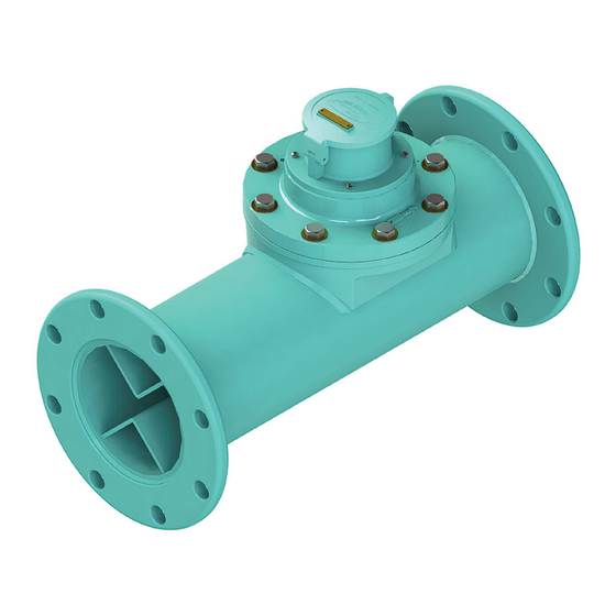
- Page 1 LTRA Water Specialties Mainline Flow Meters Models MLE MLF MLU TP1 with Mechanical Registers Sizes 24” - 54” Installation, Operation and Maintenance Manual Previously for Models ML03 ML19 MLT1 30125-99 Rev. 1.0 11OCT2024 Hach’s Flow Solutions by...
-
Page 2: Table Of Contents
Contents SAFETY SYMBOLS AND WARNINGS . . . . . . . . . . . . . . . . . . . . . . . . . . . . . . . . . . . . . . . . . . . . . . . . . . . . . . . . . . . . . . . . . .1 Safety Warnings . -
Page 3: Safety Symbols And Warnings
Safety Warnings When installing, operating, and maintaining McCrometer equipment where hazards may be present, you must protect yourself by wearing Personal Protective Equipment (PPE) and be trained to enter confined spaces. Examples of confined spaces are manholes, pumping stations, pipelines, pits, septic tanks, sewage digesters, vaults, degreasers, storage tanks, boilers, and furnaces. -
Page 4: Installation
When uncrating the meter, any damage due to rough or improper handling should be reported to the transportation firm and McCrometer. If for any reason it is determined that the unit or parts of the unit should be returned to the factory, please contact McCrometer for clearance prior to shipment. -
Page 5: Welding Saddle Attachment
Tighten the meter head bolts securely. 1 .8 Register extension Instructions for installing the CN02 register extension with a flow meter can be found on the McCrometer Web site. See Lit. # 30116-03. Direct link to document: https://bit.ly/3xdYgqB Link to Water Specialties document downloads: https://bit.ly/3rG9Aus... -
Page 6: Parts List
Maintenance and Repair LTRA 2 .1 Parts list All parts listed below are cross-referenced with call-outs in the meter assembly line drawing on the next page. (Figure 1) No. Qty. Part No. Description No. Qty. Part No. Description 7-MLT1-* Main line meter head assembly 1-1103-8-7 Screw, miter gear frame mounting (ea.) -
Page 7: Meter Assembly Drawing
Maintenance and Repair LTRA 2 .2 Meter assembly drawing Meter head assembly (13, 52 - 55) Totalizer and bonnet assembly (1 - 8) Vertical shaft assembly (12, 14 - 16) Gearbox (17 - 20) Miter gear frame assembly (21 - 33) Propeller assembly (39 - 51) Separator/support spindle assembly (34 - 38) Figure 1 . -
Page 8: Removing The Meter Head Assembly
Maintenance and Repair LTRA 2 .3 Removing the meter head assembly Refer to Figure 2 and Figure 3. Remove the meter head assembly (#13) from the service line by removing the meter head bolts (#53) and lifting up the rear (downstream) portion of the meter head (#13). -
Page 9: Service Procedure
Maintenance and Repair LTRA 2 .4 Service procedure The service procedure involves removing, cleaning, and inspecting the meter’s components and assemblies for wear and damage. It is performed in this order: Section Procedure Inspect all internal meter parts as you Meter head assembly removal proceed. -
Page 10: Remove And Inspect Vertical Shaft Assembly And Gearbox
Maintenance and Repair LTRA 2 .4 .2 Remove and inspect vertical shaft assembly and gearbox Refer to Figure 5 at right. The gearbox (#17) is sealed and filled with gearbox oil. Before disassembling lower meter assembly, the oil must be drained. Remove two screws (#16) inside the meter head (#13). -
Page 11: Remove And Clean Propeller Assembly
Maintenance and Repair LTRA If the assembly spins freely and the miter gears are not miter gear is located or the meter will subtract from worn, continue to step 2.4.4. No further inspection or the totalizer. disassembly of the unit is needed. Remove the drive miter gear assembly (#26) as follows: If the unit does not spin freely or if the miter gears are Loosen the Allen head set screw on the side of the... -
Page 12: Remove And Clean Separator/Support Spindle Assembly
Maintenance and Repair LTRA Insert tool T-2402X-1 (Figure 8) into the propeller through the threaded nose. The tabs in the tool should engage in the screwdriver slot in the end of the reverse thrust bearing cartridge (#46). Figure 8 . Tool T-2402X-1 d. -
Page 13: Reinstall Propeller And Propeller Assembly
If it is determined that the meter should such that the drive clevis portion of the driven be returned for repair, please notify McCrometer prior miter gear shaft (#29) can accept the driven clevis to shipment. Each meter must be properly packaged to portion of the vertical shaft assembly (#14). - Page 14 Maintenance and Repair LTRA Insert the vertical shaft assembly (#14) as follows. Check the totalizer drive magnet assembly (#12) again to make certain it is properly set to drive the totalizer Gently insert the vertical shaft assembly (#14) into (#4). (See section 2.4.1 step 4.) the gearbox (#17) through the opening in the top of the meter head (#13).
-
Page 15: Reinstalling The Meter Head Assembly
Maintenance and Repair LTRA 2 .6 Reinstalling the meter head assembly See section 1.7. This procedure applies to both new meter head installation and reinstallation of meter head after maintenance. (Figure 11) Set the meter assembly on the saddle as shown Tilt the meter head assembly forward, allowing with one propeller blade pointing down. -
Page 16: Troubleshooting And Service Schedule
Troubleshooting and Service Schedule LTRA 3 .0 TROUBLESHOOTING AND SERVICE SCHEDULE Meter not reading I s t h e f l o w r a t e a b o v e t h e accurately m i n i m u m r e q u i r e d f o r t h e m e t e r ? Y e s I s t h e r e a f u l l p i p e o f w a t e r ? -
Page 17: Ordering Replacement Parts
Prior to calling for a return authorization number, determine the model number, serial number (located inside the front panel of the converter), and reason for return. • Contact McCrometer Customer Service Department and ask for a Return Authorization (RA) number. • Telephone: 1-800-220-2279 •... -
Page 18: Warranty
Current as of: 1/5/2021 ProComm converter warranty - EN McCrometer warrants that this product will be free from Purchaser’s sole remedy and manufacturer’s sole obligation defects in material and workmanship for a period 12 for alleged product failure, whether under warranty... - Page 19 Fax: 951-652-3078 customerservice@mccrometer.com www.mccrometer.com USA Copyright © McCrometer, Inc. All printed material should not be changed or altered without permission of McCrometer. Any published pricing, technical data, and instructions are subject to change without notice. Contact your McCrometer representative for current pricing, technical data, and instructions.
Need help?
Do you have a question about the Hach UltraMag MLE and is the answer not in the manual?
Questions and answers