Table of Contents
Advertisement
Quick Links
About This Quick Start Guide . . . . . . . . . . . 1
General Installation Considerations . . . . . . 2
Check Shipping Crate Contents . . . . . . . . . 2
Check Serial Numbers . . . . . . . . . . . . . . . 2
Pipe Run Requirements . . . . . . . . . . . . . . 3
Sensor Position and Location . . . . . . . . . . 3
Grounding . . . . . . . . . . . . . . . . . . . . . . . 4
WARNING!
!
Incorrect installation or removal of meters can result in serious injury or death . Read
the instructions in this guide on the proper procedures carefully.
WARNING
Any person installing, inspecting, or maintaining a McCrometer flowmeter should have a
working understanding of piping configurations and systems under pressure.
Before adjusting or removing any meter, be certain the system has depressurized
completely.
Be careful when lifting meters. Meters can cause serious injury if lifted incorrectly or
dropped.
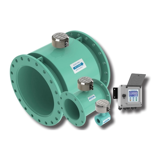
Electromagnetic Flow Meter
Quick Start Installation Guide
About This Quick Start Guide
This Quick Start Guide is a supplement to the
Installation, Operation and Maintenance manual
supplied with this meter. It is intended to be
a quick reference for the basic installation and
reading of the UltraMag.
information concerning the external connections,
external power, or pulse output, please refer to the
meter manual (Ultra Mag IOM manual, lit #30119-
03) downloadable from www.mccrometer.com.
Page 1
Battery Powered
30120-71, Rev. 1.9
Standard Model
For use in non-hazardous locations
HL Model
For use in hazardous locations:
• Class I, Division 2, Groups A-D, T5
• Class I, Zone 2 IIC T5
For more detailed
30120-71 Rev. 1.9 | 13AUG2020
13AUG2020
Advertisement
Table of Contents

Related Manuals for McCrometer UltraMag Standard


Summary of Contents for McCrometer UltraMag Standard
-
Page 1: Table Of Contents
WARNING Any person installing, inspecting, or maintaining a McCrometer flowmeter should have a working understanding of piping configurations and systems under pressure. Before adjusting or removing any meter, be certain the system has depressurized completely. -
Page 2: General Installation Considerations
When uncrating the Ultra Mag, any damage due to General Installation Considerations rough or improper handling should be reported to the transportation firm and McCrometer. If for Proper meter installation is the first step to ensure any reason it is determined that the unit or parts excellent meter performance. -
Page 3: Pipe Run Requirements
Pipe Run Requirements Sensor Position and Location Pipe Diameters The meter needs to be located a minimum distance before and after flow disturbances, For proper accuracies any 90 or 45 degree elbows, such as elbows, pumps, partially opened valves, valves, partially opened valves etc. should be and changes in pipe diameter. -
Page 4: Grounding
• The grounding rings and gaskets must be used to ensure a positive seal at the flanges, and to ensure fluid is properly grounded to sensor. For best performance, McCrometer provides grounding rings, which should be installed for all sizes. - Page 5 3 . Sensor grounding for meters in an electrically noisy environment If there is electrical noise in the fluid column or electrical current in the pipe, it can be minimized or eliminated using grounding rings or by grounding the pipeline. a .
-
Page 6: Procomm Converter Wiring Connection
TO SPI SENSOR Copyright © 2020 McCrometer, Inc. All printed material should not be changed or altered without permission of McCrometer. Any published pricing, technical data, and instructions are subject to change without notice. Contact your McCrometer representative for current pricing, technical data, and instructions.
Need help?
Do you have a question about the UltraMag Standard and is the answer not in the manual?
Questions and answers