
Subscribe to Our Youtube Channel
Related Manuals for McCrometer WATER SPECIALTIES FlowCom FC101


Summary of Contents for McCrometer WATER SPECIALTIES FlowCom FC101
- Page 1 FC101 FlowCom Register Installation, Operation and Maintenance Manual 30119-50 Rev. 2.2 July 23, 2020...
-
Page 2: Table Of Contents
Contents SAFETY WARNINGS . . . . . . . . . . . . . . . . . . . . . . . . . . . . . . . . . . . . . . . . . . . . . . . . . . . . . . . . . . . . . . . . . . . . . . . . . 1 1 .0 INTRODUCTION . -
Page 3: Safety Warnings
SAFETY WARNINGS SAFETY WARNINGS When installing, operating, and maintaining McCrometer equipment where hazards may be present, you must protect yourself by wearing Personal Protective Equipment (PPE) and be trained to enter confined spaces. Examples of confined spaces are manholes, pumping stations, pipelines, pits, septic tanks, sewage digesters, vaults, degreasers, storage tanks, boilers, and furnaces. -
Page 4: Introduction
4-20mA signal. The FlowCom can be fitted to any new or existing Water Specialties propeller flowmeter. 1 .2 Features • Retrofits to any existing McCrometer Mc Propeller • 6–10 Year Battery Life Flowmeter • NEMA 4X Enclosure with Non-intrusive Register •... -
Page 5: Installation
INSTALLATION 2 .0 INSTALLATION Enclosure lid After unpacking the register assembly, verify that the meter serial number engraved on the enclosure lid is correct. Then confirm the information on a white label Baseplate 9 4 4 6 0 6 located on the bottom of the base plate (Figure 1.) Figure 1 . - Page 6 INSTALLATION Figure 3 . Conversion Kit - FC101-01-K, FC101-02-K, FC101-03-K, Meter Mount Parts Diagram Description Quantity Part Number FlowCom Unit FC101-01 Propeller Assembly Bagged parts: Separator 4-2455-2-D Grounding Kit Instructions 30110-18 Sensor 4-2745-2 Reverse Thrust Brg Tool T2402X-1 Magnet Wand FC100-M Back Plate 2-2731-SS...
- Page 7 INSTALLATION STEP 1: Remove the flowmeter . Remove pressure from the pipeline. Remove the entire flowmeter from the pipeline. CAUTION! Never remove a meter or top plate assembly while the line is under pressure! STEP 2: Remove the totalizer assembly . Remove the entire totalizer or indicator-totalizer register assembly.
- Page 8 INSTALLATION STEP 3: Remove the gearbox assembly . For ML, LP, and OF meters: Remove the miter gear frame assembly by releasing the four screws out of the back of the gearbox. Caution: The gearbox oil will begin draining as Miter Gear soon as the seal is broken.
- Page 9 INSTALLATION STEP 4: Reassemble the gearbox assembly . Before you begin, make sure the gearbox or drop pipe and separator/spindle assembly are dry and free of oil. For ML and LP meters: Push the sensor assembly Back Plate through the back of the gearbox all the way into the separator/spindle assembly.
- Page 10 INSTALLATION STEP 5: Connecting the sensor wires The connection shown below is typical of all Water Specialties Electronic Propeller Flow Meters. Clean the meter head surface of all dirt, glue, gaskets, etc. b. Verify that an O-ring is installed at the bottom of the electronic register base plate. Connect the sensor cable to the in-line terminal blocks.
-
Page 11: Mechanical-To-Flowcom Conversion Kit Installation - Remote Mount
INSTALLATION 2 .2 Mechanical-to-FlowCom Conversion Kit Installation - Remote Mount Check the parts received against the parts list and Figure 5 and Figure 6 below. Contact the factory to report any discrepancies. Figure 5 . Conversion Kit for Table Shown Below For FlowCom models with remote: FC101-00-K, FC101-01-K, FC101-02-K, FC101-03-K with remote mount . - Page 12 INSTALLATION Figure 6 . Conversion Kit for Tables Shown Below For FlowCom models FC101-01-R, FC101-02-R, FC101-03-R . Refer to Figure 6 above . Parts Diagram Description Quantity Part Number FlowCom Unit FC101-01 Bagged parts: Grounding Kit Instructions 30110-18 Sensor 4-2745-2 Magnet Wand FC100-M Screw 10-32 x 1.25”...
- Page 13 INSTALLATION STEP 1: Install submergible remote mount kit in the meter head plate If the submergible remote mount assembly has not already been installed in the meter head plate, you need to assemble it. Use remote cable Figure 7 at right as a guide for this step. Follow steps 1 through 4 from section 2.1.
- Page 14 INSTALLATION STEP 2: Test the FlowCom . Test the conversion by spinning the propeller by hand and ensuring the display changes. Install the meter into the line and mount the remote FlowCom in a convenient location. STEP 3: Ground the Flowcom . Following the Grounding Kit Instructions, connect the ground wire to the Flowcom and other systems that may be attached.
-
Page 15: Output Wiring Connection
Output Wiring Connection 3 .0 OUTPUT WIRING CONNECTION 3 .1 Wiring Diagrams Isolated Power Supply FC100 Output Cable FC101 Output Cable 12-40VDC RED (+) BLACK (-) Instrument Note: This Side Is Already Connected Internally To Ground Figure 9 . Output Type: 4-20mA Current Loop (Meter-mounted version) Housing Label:1 (Figure 11) Note: Power Supply Does Not Power Supply... - Page 16 Output Wiring Connection PLC or Counter with Notes: Isolated Power Supply Power Supply Must Be Isolated. 12-40VDC Open Collector Only To Be Used With Battery-Powered Units. FC100 Output Cable FC101 Output Cable WHITE (+)(OC+) GREEN (-)(OC-) Figure 12 . Output Type: Open Collector Powered by Instrument with Internal Resistor Housing Label: 2 (Figure 14) FC100 Output Cable FC101 Output Cable...
- Page 17 Output Wiring Connection Red to VCC Wiegand Sensor Black to IO-2 EB420-02 Board Figure 15 . Output Type 4-20mA Current Loop (Remote-mounted version) In The Presence Of Environmental Noise (VFDs, RF Transmitters, etc .) *IMPORTANT: SEE NOTES . Housing Label: 1 (Figure 11) *IMPORTANT NOTES: 4-20mA Current Loop In Presence Of Environmental Noise (VFDs, RF Transmitters etc.) •...
-
Page 18: 4-20Ma Connection To Water Specialties Instrumentation
Output Wiring Connection 3 .2 4-20mA Connection To Water Specialties Instrumentation IN60 – Flow Computer Connection Connection IN60 Term. Strip Pin 16 (Iso. +12 VDC) FC101 Output Cable Red (+) IN60 Term. Strip Pin 4 (input) FC101 Output Cable Blk (-) IN41 –... -
Page 19: Lcd Output Symbol Clarifications
Output Wiring Connection 3 .3 LCD Output Symbol Clarifications PULSE SYMBOL 4-20mA SYMBOL BATTERY SYMBOL FLOW RATE DIGITS FLOW RATE UNIT FLOW TOTAL DIGITS FLOW TOTAL UNIT FLOW TOTAL MULTIPLIER FC101 Screen Symbols Figure: 28 SCENARIO RESULT The 4-20mA full scale is not defined and the There is no 4-20mA output and the “4-20mA”... -
Page 20: Programming
PROGRAMMING 4 .0 PROGRAMMING 4 .1 Accessing The Configuration Menu Hold the magnetic wand as noted in Figure 27 below. After five seconds the register will display “Loc-Code”. A lock code of 01000 is required to enter the configuration menu . Use the magnetic wand to input the lock code and then pass the wand over the “P”... -
Page 21: Menu Table Of Contents
PROGRAMMING 4 .3 Menu Table Of Contents First Menu Level Second Menu Level Display Menu Title Description Display Menu Title Description Parent Meter Program Lock Enter w/preset Sets Meter Serial Loc-CodE Par-S Serial # code rAtE-Un Rate Unit/Time Sets Unit/Time Sets Register SErno Register Serial #... -
Page 22: Menu Navigation
PROGRAMMING 4 .4 Menu Navigation First Menu Level Loc-CodE Screen .... "Rate" line Name Reed Switch Icons "Totalizer" line Displayed PROGRAM Screen activated while in Run Mode by activating "P" reed switch for approximately 5 seconds. First Menu Level Change Digit. - Page 23 PROGRAMMING First Menu Level rAtE-Un rAtE-dP tot-Un Display Units of Measure Un 22 Barrels per day (42G) Un 21 Barrels per hour (42G) From Un 20 Barrels per minute (42G) Lock-Out Un 19 Barrels per day (55G) Menu Un 18 Barrels per hour (55G) Un 17 Barrels per minute (55G)
- Page 24 PROGRAMMING First Menu Level tot-dP-E tot-dP Tot-FAct 20mA-Un From Totalizer Unit Menu Display Default is Totalizer “No”. Show tot-dp-E on totalizer line Decimal Selecting Change setting. blinking “yes” on rate line. “Yes” will Place enable Totalizer Multiplier. tot-dP-E Totalizer DP - Enable/ Disable Version 2.3 And Higher Show "tot-dP"...
- Page 25 PROGRAMMING First Menu Level 20mA-dP 20mA-FS PLS-Un From 20mA Unit Menu Show "20mA-dP" onTotalizer line. Display Move DP to desired location. Blink current setting or display 20mA DP Default is "0" (no DP). DP blinks until selected. blinking "0" on Rate line. Cycles the DP from the 0.00 current selection, from right...
- Page 26 PROGRAMMING First Menu Level PLS-dP PLS-Inc CAL-Pct -Go to From Pulse Unit Menu Display Pulse Move DP. Show "PLS-dP" on Totalizer line. Blink current Decimal DP blinks until Default is "0" (no DP). DP or display blinking "0" on Rate line. Place selected.
- Page 27 PROGRAMMING Second Menu Level Par-S SErno Display Change Digit. Digit blinks until selected. Show "Par-S" on Rate line. Parent Meter Right Digit or current setting blinks Serial UP arrow cycles through on Totalizer line. Move Cursor Left to Number each digit. LEFT arrow next digit position.
- Page 28 PROGRAMMING Second Menu Level Set-CodE GPr-dP Smooth From Register Serial Number Menu Display Default is "0". UP arrow cycles through Change Digit. each digit. LEFT arrow Digit blinks until selected. moves to next digit Set Program Show "SEt-CodE" on Totalizer line. location from right to left.
- Page 29 PROGRAMMING Second Menu Level 4mA-AdJ 20mA-AdJ PLS-tYPE PLSwidth ** From Smoothing Menu increase Show "4mA-AdJ" on Totalizer line. Change value. Value Display Blink current setting or display ".00" Trim 4 mA blinks until selected. to .50 on Rate line. decrease Default is ".00".
- Page 30 PROGRAMMING Second Menu Level RESEttot DIS-rSt tot-S Au-InP From Pulse Width Menu DIS-rSt ? Show "rESEttot" on Totalizer line. Change value. Value Display Reset Total Default is "no". (from Flash) Blink "no" on Rate line. blinks until selected. Selecting "YES" will reset any totalizer value rESEttot...
- Page 31 PROGRAMMING Second Menu Level cutoff PLS-Pr -Go to From Aux. Input Menu Display Change Digit. Default is "0". UP Digit blinks until selected. Show "cuto " on Totalizer line. arrow cycles Low-Flow Blink “0” on Rate line. through each digit. Cuto Move Cursor Left to next LEFT arrow...
-
Page 32: Configuration Examples
PROGRAMMING 4 .5 Configuration Examples Example 1: Register With DC-powered Optically-isolated O .C . Pulse Output Meter Size : 6” Gallons Per Revolution: 1.4815 Rate Units: Cubic Feet per Second Totalizer Units: Acre Feet x 0.001 4-20mA Full Scale: 2.5 CFS Switch Closure Output: 1 Switch for Every 1000 Gallons Sensor Type:... - Page 33 PROGRAMMING Example 2: Register With Battery-powered O .C . Pulse Output Meter Size : 24” Gallons Per Revolution: 37.0 Rate Units: Totalizer Units: Gallons x 10000 Open Collector Pulse Output: 1 Pulse for Every 0.01 Acre Foot Pulse Width: 0.1 milliseconds Sensor Type: 2 PPR Configuration Settings:...
- Page 34 PROGRAMMING Example 3: Register With 4-20mA Transmitter Output Meter Size : 4” Gallons Per Revolution: Rate Units: Liters Per Hour Totalizer Units: Metric Ton x 1 4-20mA FS: 100 LPM Sensor type: 2 PPR Configuration Settings: Menu Item Display Menu Item Description Item Selection rAtE-Un Rate Unit...
-
Page 35: Product Specifications
.01 mA to .50 mA Meter Rating (with IP67 Remote Mount): Input Signal Engineering/Time Units: 22 different units Input Compatibility: McCrometer Flowmeters Pulse Outputs Remote Distance: 50 feet max. Engineering Units: 20 different units Rate Functions Optically Isolated Pulse Display:... -
Page 36: Dimensions
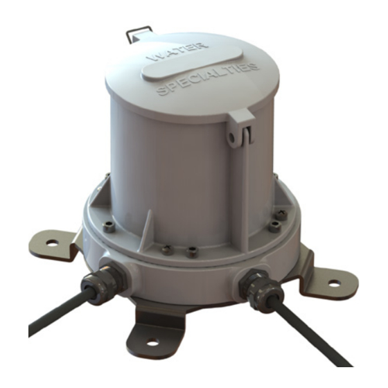
PRODUCT SPECIFICATIONS 5 .2 Dimensions ASSEMBLY MOUNTING SCREWS ENCLOSURE SEALING SCREWS (6) SOCKET HEAD CAP SCREWS 5.07 (128.8mm) 5.5 inches (139.7mm) Figure 17 . FlowCom Housing 5 .3 Housing The enclosure assembly is sealed by six socket head cap screws. The enclosure cover and base are made of aluminum and coated for all weather use. -
Page 37: Parts List
PRODUCT SPECIFICATIONS 5 .4 Parts List Figure 18 . FlowCom Replacement Parts Ref . Part Number Description R0710-60 Canopy Enclosure Water Specialties 10730 Screw 10-32 x 1.25” Long Fillister Head 10602 Screw 10-32 x 0.5” Long Socket Head Cap ELR500-01 Electronic Register, FlowCom EZ100-00 Battery C 3.6V Lithium... -
Page 38: Product Maintenance
PRODUCT MAINTENANCE 6 .0 PRODUCT MAINTENANCE 6 .1 Battery Replacement To replace the battery the canopy enclosure must be removed. The time period which the enclosure is opened should be minimized to reduce moisture and contamination. The battery holder may have a zip tie or other locking mechanism in place which can be removed. -
Page 39: Troubleshooting
TROUBLESHOOTING 7 .0 TROUBLESHOOTING Inaccurate Rate And Total Readings . A. Check the gallons per revolution (GPR) and pulses per revolution (PPR) settings. The electronic register could be programmed with incorrect GPR and PPR values. B. Check that the input sensor cable’s shield wire is connected to the earth ground, per instructions on tag. Also, check the connection of the shield wire on the outside instrumentation side of the output cable, per instructions on tag. -
Page 40: Circuit Board Connections
TROUBLESHOOTING 7 .1 Circuit Board Connections The circuit board does not have any serviceable components. Each register is shipped with the cables connected to the appropriate input and output connections per the customer requirements. The circuit board layout is contained in this manual as a technical support reference manual as a technical support reference. -
Page 41: Warranty Statement
Computing devices sold but not manufactured by McCrometer, Inc. are covered only by the original manufacturer’s written warranty. Hence, this warranty statement does not apply. - Page 42 ™ Copyright © 2001-2020 McCrometer, Inc. All printed material should not be changed or altered without permission of McCrometer. Any published pricing, technical data, and instructions are subject to change without notice. Contact your McCrometer representative for current pricing, technical data, and instructions.
Need help?
Do you have a question about the WATER SPECIALTIES FlowCom FC101 and is the answer not in the manual?
Questions and answers