
Related Manuals for McCrometer Hach Ultra Mag 5000


Summary of Contents for McCrometer Hach Ultra Mag 5000
- Page 1 LTRA Ultra Mag 5000 Electromagnetic Flow Meter Installation, Operation and Maintenance Manual 30126-06 Rev. 1.0 26AUG2024 Hach’s Flow Solutions by...
-
Page 2: Table Of Contents
Contents SAFETY . . . . . . . . . . . . . . . . . . . . . . . . . . . . . . . . . . . . . . . . . . . . . . . . . . . . . . . . . . . . . . . . . . . . . . . . . . . . . . . . . . . . . 1 Safety Symbols And Warnings . -
Page 3: Safety
Safety Warnings When installing, operating, and maintaining McCrometer equipment where hazards may be present, you must protect yourself by wearing Personal Protective Equipment (PPE) and be trained to enter confined spaces. Examples of confined spaces are manholes, pumping stations, pipelines, pits, septic tanks, sewage digesters, vaults, degreasers, storage tanks, boilers, and furnaces. -
Page 4: Description Of The Flow Meter
When uncrating the Ultra Mag, any damage due to rough or improper handling should be reported to the transportation firm and McCrometer. If for any reason it is determined that the unit or parts of the unit should be returned to the factory, please contact McCrometer for clearance prior to shipment. -
Page 5: Preparing For A New Installation
PREPARING FOR A NEW INSTALLATION LTRA 3 .0 PREPARING FOR A NEW INSTALLATION 3 .1 Meter Mounted Sensor Location Adjoining pipe must be adequately supported, and the area around the sensor should provide sufficient drainage to prevent flooding the transmitter or conduits. The location chosen should provide room to read the display and be free from harsh electrical noise from adjacent equipment, cables, R.F.I., or E.M.I. -
Page 6: Flow Meter Installation
FLOW METER INSTALLATION LTRA 4 .0 FLOW METER INSTALLATION NOTE Nothing in this manual supersedes local codes. NOTE The flow of the medium should correspond to the direction shown by the arrow on the sensor. 4 .1 Flanged Meter Installation Install the Ultra Mag flow meter inline between two flanged end pipes. -
Page 7: Remote Mount Transmitter Installation
REMOTE MOUNT TRANSMITTER INSTALLATION LTRA 5 .0 REMOTE MOUNT TRANSMITTER INSTALLATION 5 .1 Mounting the ProComm Max Transmitter Note: This applies to the remote mount transmitter only. If possible, mount the transmitter in an electronics shed or environmental enclosure. The sun shield should be oriented in a direction to reduce sun damage and ensure readability. -
Page 8: Cable Gland Assignment For Wiring Harnesses
REMOTE MOUNT TRANSMITTER INSTALLATION LTRA The remote mount transmitter is shipped with five 1/2" NPT cable glands. Up to three cable glands may be removed and replaced with 1/2" conduits. Figure 6 . Remote mount Figure 7 . Remote mount transmitter with five cable transmitter with three conduit gland pass-throughs... -
Page 9: Pulling Sensor Cable Through Electrical Conduit
REMOTE MOUNT TRANSMITTER INSTALLATION LTRA Chassis Sensor Outputs cable Power Output Outputs Power Sensor cable Figure 10 . Remote mount transmitter cable assignments 5 .4 Pulling Sensor Cable Through Electrical Conduit It is very important to protect the end of the sensor cable when pulling it through a conduit. Water can accumulate in low portions of conduit. -
Page 10: Cabling And Connecting Wiring
Quick Connect Cable Ends (optional) IMPORTANT Connections to the sensor must be made with cable supplied by McCrometer specifically for that purpose. Do not substitute the supplied cable with other types of cable, even for short runs. Quick Connect cable end fittings are optional. If selected at the time of order, follow the instructions below. -
Page 11: Terminal Block Diagram
Remote Mount Cable Connection to Sensor The ProComm Max transmitter is designed to connect to a single-port converter box CABLING AND CONNECTING WIRING mounted on meter. See Figure 12 as an example showing the Ultra Mag meter. This design LTRA converts ow data and sends it to the ProComm Max transmitter. -
Page 12: Wiring Diagrams
CABLING AND CONNECTING WIRING CABLING AND CONNECTING WIRING LTRA Wiring Diagrams 6 .4 Wiring Diagrams CAUTION - Always disconnect the power cord before attempting any electrical connections. BOTH METER MOUNT METER MOUNT ONLY AND REMOTE MOUNT OUTPUTS COILS ELECTRODES DIGITAL 4-20 Terminal Block Assignments Terminal... -
Page 13: Transmitter Power Wiring Diagram
CABLING AND CONNECTING WIRING CABLING AND CONNECTING WIRING LTRA 6 .6 Transmitter Power Wiring Diagram Transmitter Power Wiring Diagram WARNING! WARNING! Hazardous supply voltage can shock, burn, or cause death. Hazardous supply voltage can shock, burn, or cause death. These instructions are for connecting either the AC or DC power option. The connections are shown below above the appropriate power card. -
Page 14: 4-20Ma Hook-Up
CABLING AND CONNECTING WIRING CABLING AND CONNECTING WIRING LTRA 6 .7 4-20mA Hook-Up 4-20mA Hook-Up Output type: 4-20mA current loop, sink powered (passive) 4-20mA - Terminal 21 4-20mA - Terminal 22 Output type: 4-20mA current loop, source powered (active) 4-20mA - Terminal 21 4-20mA - Terminal 22 Figure 16. -
Page 15: Optional Smart Output Hook Up
Green interface cable and make direct connection via the wiring table shown at right. Neptune Black Green • Signals and associated wire colors in the McCrometer Sensus Green Black SmartOutput™ interface cable are identi ed together in SmartTrax Brown Black Gray the top row of the table at right. -
Page 16: 6 .11 Pin-Out Of Male And Female Connectors
CABLING AND CONNECTING WIRING CABLING AND CONNECTING WIRING LTRA 3.10 Pin-out of Male and Female Connectors 6 .11 Pin-out of Male and Female Connectors Black FEMALE CABLE Brown Gray 4-20mA & Power White Connector Blue Figure 19. Pin-out of Female Connector Figure 20 . -
Page 17: Sensor Grounding
Field Mag sensor have a non-conductive coating and may not require grounding rings. For best performance, McCrometer provides grounding rings for all sizes. For best performance, grounding the uid column is recommended when the meter is installed in an electrically noisy environment, such as with VFD pumps or nearby electrical systems with insu cient grounding. -
Page 18: Replacement Parts
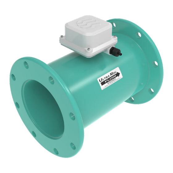
REPLACEMENT PARTS LTRA 8 .0 REPLACEMENT PARTS The image above is representative for all Ultra Mag meter models and sizes. PART NUMBER DESCRIPTION PC-RA1 AC Transmitter 4-20mA Output PC-RD1 DC Transmitter 4-20mA Output PC-RA2 AC Transmitter w/ Modbus RS485 Communications Protocol PC-RD2 DC Transmitter w/ Modbus RS485 Communications Protocol 15035 / 15036... -
Page 19: Speci Cation Sheet
• Ultra Mag 5000: ProComm Max transmitter Transmitter Mount Either meter mount or remote mount • Standard: 25’/7.6 m McCrometer supplied submersible cable with each remote mount unit. • Optional: Up to 500’/152.4 m, or 25’/7.6 m max for ProComm GO Sensor Cable Lengths •... - Page 20 Multiple point wet ow calibrations are conducted on every complete ow tube with its signal transmitter. If desired, the tests can be witnessed by the customer. The McCrometer test facilities are traceable to the National Institute of Standards & Technology. Uncertainty relative to ow is ±0.15%.
-
Page 21: Flow Meter Dimensions And Weights
Speci cation Sheet SPECIFICATIONS, WEIGHTS, AND DIMENSIONS LTRA Ultra Mag Flow Meter LTRA 9 .2 Flow Meter Dimensions and Weights Flow Meter Dimensions and Weights 1½” to 3" Models DIMENSIONS Est. Shipping (Lay Lengths) Weight (lbs.)* Flow Ranges Pipe Size (0.2 to 32 FPS) (Nominal) CL150... - Page 22 Speci cation Sheet LTRA Ultra Mag Flow Meter SPECIFICATIONS, WEIGHTS, AND DIMENSIONS LTRA Dimensions and Weights (cont.) 4" to 12" Flanged End Body Style DIMENSIONS Est. Shipping Weight (Lay Lengths) (lbs.)* Flow Ranges Pipe Size (0.2 to 32 FPS) (Nominal) Min-Max GPM AWWA ANSI...
- Page 23 Speci cation Sheet SPECIFICATIONS, WEIGHTS, AND DIMENSIONS LTRA Ultra Mag Flow Meter LTRA Flow Meter Dimensions and Weights (cont .) Dimensions and Weights (cont.) 14+" Flanged End Body Style DIMENSIONS Est. Shipping Weight (lbs.)* Flow Ranges Pipe (0.2 to 32 Size AWWA ANSI...
-
Page 24: Procomm Max Transmitter Specifications
SPECIFICATIONS, WEIGHTS, AND DIMENSIONS SPECIFICATIONS LTRA 9 .3 ProComm Max Transmitter Specifications 10.0 SPECIFICATIONS Physical Speci cations Electronic Housing Diecast aluminum, powder coated enclosure w/ tamper resistant seal Remote Mount: Height: 7.3” (18.5 cm) Width: 8.5” (21.6 cm) Transmitter Depth: 4.3” (10.9 cm) Dimensions Meter Mount: Height: 6.9”... - Page 25 DIMENSIONS SPECIFICATIONS, WEIGHTS, AND DIMENSIONS LTRA 11.0 DIMENSIONS 9 .4 ProComm Max Transmitter Dimensions Meter Mount Transmitter Dimensions Height 6.9” (17.6 cm) Width7.4” (18.8 cm) Depth 5.6” (14.2 cm) 5.6" 6.9" 3" 4.4" 2.5" 3.1" 7.4" 5.6" 140º 10.25" 5.7" 3.1"...
-
Page 26: Procomm Max Transmitter Dimensions
SPECIFICATIONS, WEIGHTS, AND DIMENSIONS DIMENSIONS LTRA Remote Mount Transmitter Dimensions Height 7.4" (18.9 cm) Width 8.5" (21.6 cm) Depth 4.4" (11.2 cm) 4.4" 7.0" 2.25" C TO C 7.4" 7.5" C TO C 8.5" 140º 10.3" 8.7" Page 24 30127-20 Rev. 1.0 | 23AUG2024 Page 24 30126-06 Rev. -
Page 27: Returning A Unit For Repair
• Email: customerservice@mccrometer.com • Please make sure the meter is clean and free from foreign debris prior to shipping. McCrometer may charge a cleaning fee if the meter is sent without being cleaned. • Ship the meter in the original packaging, if possible. Do not ship manuals, power cords, or other parts with your unit unless required for repair. -
Page 28: Warranty
McCrometer, free of charge, FOB the factory in Hemet, the Warranty period at the manufacturer’s option and California, within a period of two (2) years from the date of expense, without obligation to renew the expired Warranty delivery. - Page 29 Fax: 951-652-3078 customerservice@mccrometer.com www.mccrometer.com USA Copyright © McCrometer, Inc. All printed material should not be changed or altered without permission of McCrometer. Any published pricing, technical data, and instructions are subject to change without notice. Contact your McCrometer representative for current pricing, technical data, and instructions.
Need help?
Do you have a question about the Hach Ultra Mag 5000 and is the answer not in the manual?
Questions and answers