Table of Contents
Advertisement
Quick Links
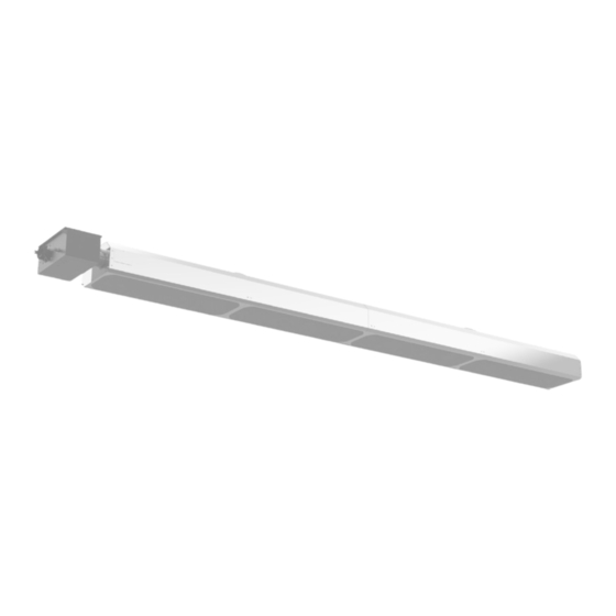
Decorative Two Stage Infrared Patio Heaters
WARNING
!
1. Improper installation, adjustment, alteration,
service or maintenance can cause property
damage, injury or death, and could cause
exposure to substances which have been
determined by various state agencies to cause
cancer, birth defects, or other reproductive
harm. Read the installation, operating, and
maintenance instructions thoroughly before
installing or servicing this equipment.
2. Do not locate ANY gas-fired units in areas
where chlorinated, halogenated, or acidic
vapors are present in the atmosphere. These
substances can cause premature heat
exchanger failure due to corrosion which can
cause property damage, serious injury or
death.
3. For either indoor or outdoor installation. Not
for use in residential dwellings.
CAUTION
!
As with all infrared equipment, clearances to
combustible materials are critical. Be sure all
units have reflectors installed along the entire
length of the tube, and that they are not
mounted at an angle greater than 45° from the
horizontal plane. In locations used for storage
of combustible materials, signs shall be clearly
posted in the vicinity of the heater where readily
apparent to material handlers to specify the
maximum permissible stacking height to maintain
required clearances from the heater to the
combustibles.
PLEASE BE SURE TO LEAVE IT WITH THE OWNER WHEN YOU LEAVE THE JOB.
INSTALLATION AND SERVICE MANUAL
THIS MANUAL IS THE PROPERTY OF THE OWNER.
FOR YOUR SAFETY
IF YOU SMELL GAS:
1. Open windows (indoor installation only).
2. Do not touch electrical switches.
3. Extinguish any open flame.
4. Immediately call your gas supplier.
FOR YOUR SAFETY
The use and storage of gasoline or other
flammable vapors and liquids in open containers
in the vicinity of this unit is hazardous.
IMPORTANT
The use of this manual is specifically intended
for a qualified installation and service agency.
A qualified installation and service agency
must perform all installation and service of
these appliances.
Inspection upon Arrival
1. Inspect unit upon arrival. In case of damage, report it
immediately to transportation company and your local
Modine Sales Representative.
2. Check rating plate on unit to verify that power supply
meets available electric power at the point of installation.
3. Inspect unit upon arrival for conformance with description
of product ordered (including specifications where
applicable).
9-516.1
August 2024
Model MRL
Advertisement
Table of Contents

Related Manuals for Modine Manufacturing MRL Series


Summary of Contents for Modine Manufacturing MRL Series
- Page 1 9-516.1 August 2024 INSTALLATION AND SERVICE MANUAL Decorative Two Stage Infrared Patio Heaters Model MRL FOR YOUR SAFETY WARNING IF YOU SMELL GAS: 1. Open windows (indoor installation only). 2. Do not touch electrical switches. 1. Improper installation, adjustment, alteration, 3.
-
Page 2: Table Of Contents
Series Contents .0 Introduction ..............3 Overview . -
Page 3: Introduction
Series Introduction • Overview • Heater Components • Specifications Introduction Overview The intent of this manual is to provide information regarding general safety, installation, operation, and maintenance of this radiant tube heater. You must read and understand all instructions and safety warnings before installing or servicing the radiant tube heater. -
Page 4: Safety Labels And Their Locations
ANSI Z83.26-2020 • CSA 2.37-2020 GAS-FIRED OUTDOOR HEATER BUILD TYPE 80,000 INFRARED PATIO HEATERS MAX. DEBIT CALORIFIQUE PRESSION A LA TUBULURE D'ALIMENTATION MODINE MANUFACTURING COMPANY THIS HEATER IS TO BE UN-VENTED ONLY BTU/h INCHES W.C. 21400 HOOVER RD., WARREN, MI 48089 FOR OUTDOOR USE ONLY. - Page 5 Series Introduction • Safety Labels and Their Locations LED CODE FAULT STATUS FAULT CODE DELAY Initial flash on power up, No fault, normal operation No delay then steady off Steady on Module failure / Internal fault No delay 1 flash Ignition failure 3 minutes APS air flow fault...
-
Page 6: Safety
Safety • Warning Symbols • Applications Series Safety Read and understand all safety information and warnings in this manual prior to installation, operation, and maintenance of this tube heater. Warnings indicate a potentially hazardous situation which, if not avoided, could result in death or injury. WARNING Improper installation, adjustment, alteration, service, or maintenance can cause property damage, serious injury, or death. -
Page 7: Standards, Certifications, And Government Regulations
Safety • Standards, Certifications, and Government Regulations Series Standards, Certifications, and Government Regulations Installation of this tube heater must conform with all applicable local, state, and national specifications, regulations, and building codes. Contact the local building inspector and/or fire marshal for guidance. In the absence of local codes, the installation must conform to the latest edition of: United States: National Fuel Gas Code, ANSI Z223.1 (NFPA 54). -
Page 8: Clearances To Combustibles
Safety • Clearances to Combustibles Series Clearances to Combustibles A critical safety factor to consider before installation is the clearances to combustibles. Clearance to combustibles is defined as the minimum distance you must have between the tube surface, or reflector, and the combustible item . -
Page 9: Mounting Angles
Series Safety • Clearances to Combustibles In locations used for the storage of combustible materials, signs must be posted to specify the maximum permissible stacking height to maintain the required clearances from the heater to the combustibles. Signs must either be posted adjacent to the heater’s thermostat or in a conspicuous location. The stated clearance to combustibles represents a surface temperature of 90°F (50°C) above room temperature. -
Page 10: Installation
Installation • Design Considerations and Prechecks Series Installation WARNING Improper installation, adjustment, alteration, service, or maintenance can cause property damage, serious injury, or death. Read and understand the installation, operation, and maintenance instructions thoroughly before installing or servicing this equipment. Only trained, qualified gas installation and service personnel may install or service this equipment. -
Page 11: Heater Dimensions
90.5” 45.6” 3.25” 195.5” SIDE VIEW 11.75” 9.5” 18.25” END VIEW Chart 3.1 • Recommended Mounting Heights and Coverages for MRL Series Heaters Distance Max. Distance Typical or Coverage Area Distance Between Between Between Max. Input Recommended Straight Config. Heaters (ft.) -
Page 12: Heater Assembly Instructions
Installation • Heater Assembly Instructions Series Heater Assembly Instructions WARNING At least two people are required to assemble and hang this heater. Failure to follow these instructions can result in property damage, serious injury, or death. Read and understand the installation, operation, and maintenance instructions thoroughly before installing or servicing this equipment. -
Page 13: Baffle Assembly
Series Installation • Heater Assembly Instructions Open the burner carton, remove the burner box, and place the kit contents box at the end of the burner end tube and reflector assembly. Disconnect the pressure switch hose, Glo-Bar connector, and flame rod wire from their respective connections on the burner tube. - Page 14 Installation • Heater Assembly Instructions Series Remove the existing #10 screw holding the exhaust diffuser and set aside (see Fig. 3.7). Insert the baffle into the exhaust tube, locking each baffle together as they are inserted. Once in the tube, ensure the baffles are in the vertical position and flush with the end of the tube as shown in Fig.
-
Page 15: Heater Placement And Suspension
Installation • Heater Placement and Suspension Series Heater Placement and Suspension WARNING Improper suspension of the tube heater may result in collapse and being crushed. Always suspend from a permanent part of the building structure that can evenly support the total force and weight of the heater. -
Page 16: Sway Bracing For High Air Movement And Outdoor Applications
Installation • Sway Bracing for High Air Movement and Outdoor Applications Series Sway Bracing for High Air Movement and Outdoor Applications For high air movement and outdoor applications, install side restraints (field supplied) to reduce side to side swaying as shown in Fig. 3.10. Side restraints should be installed so that they are angled at 45° ± 10° and should be placed at every designated suspension point. - Page 17 Installation • Egg Crate Installation • End Panel Installation Series Figure 3.11 • Egg Crate Installation Egg Crate Egg Crate Egg Crate Egg Crate End Panel Installation Once egg crates are installed, place the reflector end panel flush on the end of the reflector, ensuring edges and screw holes are aligned.
-
Page 18: Combustion Air Supply And Ventilation
Installation • Combustion Air Supply and Ventilation • Outdoor Unvented Operation Series Combustion Air Supply and Ventilation The upper levels of the space to be heated are required to be properly ventilated to supply combustion air to the heaters and to sufficiently dilute the products of combustion. It is also important to keep the flue discharge area clear of gas piping and electrical wiring. -
Page 19: Gas Supply Installation Instructions
Installation • Gas Supply Installation Instructions Series Gas Supply Installation Instructions The gas supply to the unit heater must be connected and tested in accordance with national, state, and local codes along with guidelines in this manual. In the United States, refer to the latest edition of the ANSI Z223.1 (NFPA54) Standard. - Page 20 The MRL Series heater is equipped to connect to the corrugated stainless steel tube (CSST) flexible gas connector (included). Do not connect the main gas line directly to the heaters gas inlet without the use of the flexible connector.
-
Page 21: Installation Of The Gas Line To The Heater
Installation • Installation of the Gas Line to the Heater Series Installation of the Gas Line to the Heater Install a sediment trap / drip leg in the supply line at the lowest spot prior to the gas ball valve. The trap length shall be at least three inches long. - Page 22 Installation • Installation of the Gas Line to the Heater Series Refer to Chart 3.2 for natural gas and Chart 3.3 for propane to determine the cubic feet per hour (CFH) required for the type of gas and size of unit to be installed. To determine the proper pipe diameter, use the CFH value and the length of pipe necessary from Chart 3.4.
- Page 23 175 feet 200 feet The MRL Series heater is equipped to receive a gas supply line nipple of ½” NPT Schedule 40 metallic pipe. All piping must be installed in accordance with the requirements outlined in the National Fuel Gas Code ANSI/Z223.1 (latest edition) or CSA-B149.1.
-
Page 24: Leak Testing
Installation • Gas Supply Installation Instructions • Leak Testing Series When connecting piping to the unit, the use of a thread joint compound is required. The thread compound (pipe dope) shall be resistant to the action of liquefied petroleum gas or any other chemical constituents of the gas to be conducted through the piping. -
Page 25: Electrical Requirements And Wiring Diagrams
Installation • Electrical Requirements and Wiring Diagram • Internal Wiring Diagram Series Electrical Requirements and Wiring Diagrams WARNING Shock hazard. Disconnect power supply before making wiring connections to prevent electrical shock and equipment damage. Any original factory wiring that requires replacement must be replaced with wiring material having a temperature rating of at least 105°C minimum voltage. -
Page 26: Field Wiring Supply Voltage
ANSI/NFPA 70 Standard. All field wiring to the MRL Series heater must be done in accordance with the national, state, provincial, local codes, and the guidelines in this manual. In the United States, refer to the most current revisions to the Electrical Code ANSI/NFPA 70. -
Page 27: Thermostat Connection
MRL Series heaters may be controlled by a thermostat or switch. The control voltage is 24 VAC (supplied by internal transformer) and the burner control box is equipped with a 60” black 24 VAC control wire. Do not supply 120 VAC to the 24 VAC connection. -
Page 28: Operation
Operation • Sequence of Operation Series Operation Sequence of Operation Standby: The ignition module (circuit board) continually checks for internal faults, circuit integrity, and relay contact positioning. Starting Circuit: Upon a call for heat, the control verifies that the differential switch is in the proper position (open). -
Page 29: Diagnostics
Operation • Diagnostics Series Diagnostics This heater is equipped with a resettable inline fuse. The controls will automatically lockout the heater system when an external or system fault occurs. There are two types of lockout: Soft Lockout: The heater will attempt to light three times. In the event of a failed attempt to light (gas pressure, valve, no flame sense, etc.), the heater will enter a Soft Lockout period for 30 minutes, then attempt to light three more times before entering Hard Lockout mode. -
Page 30: Troubleshooting Guide
Troubleshooting Guide Series Troubleshooting Guide Turn up thermostat. Is the power at Does the fan the heater 120 V? blower turn on? Find the source of the electrical problem between panel and heater. Is there 120 V on the Find the source of the Check the power across the primary side of the electrical problem... - Page 31 Troubleshooting Guide Series Bypassing any switch is intended for testing purposes only. Do not leave switch bypassed during NOTICE normal operation or the heater’s built-in safety mechanisms will be compromised. Remove Process Start Corrective obstruction. Question Question Action Check circuit board for Is the power across Is the power across Is the fan...
- Page 32 Troubleshooting Guide Series Continued from page 30. Test for 24 V at valve opening period (usually 30 to 45 seconds After igniter is warmed up, does gas after power to heater). Is there 24 V to valve for 8 seconds? valve open (low light illuminates)? Replace circuit board.
- Page 33 Troubleshooting Guide Series Bypassing any switch is intended for testing purposes only. Do not leave switch bypassed during NOTICE normal operation or the heater’s built-in safety mechanisms will be compromised. Check to make sure gas pressure is within minimum and maximum inputs, as indicated on the heater’s rating plate.
-
Page 34: Maintenance
Maintenance • Routine Maintenance and Inspection Series Maintenance WARNING Personal injury or death may result if maintenance is not performed by properly trained gas installer or service personnel. Contact the installing distributor or place of purchase for service. Do not operate heating system if repairs are necessary. Allow heater to cool prior to servicing. -
Page 35: Maintenance Log
Series Maintenance • Routine Maintenance and Inspection • Reflector: To maintain effective infrared heating, always keep both sides of the reflector clean. Maintenance can vary significantly depending on the environment. Dirt and dust can be vacuumed or wiped with a soap and water solution. Use metal polish if the reflectors are severely dirty. Contact service personnel if repairs are necessary. -
Page 36: Parts
Parts • Heater Components and Parts List Series Parts 264B Figure 7.1 • Burner Assembly Components 1018 802B 1135 851B 3252 383A 1428 804B 222A 3072 3014 TP-840A, 841A 303B 208A Chart 7.1 • Parts List Part No. Description Part No. Description TP-1B Control Box Cover - Black... -
Page 37: Tube And Reflector Components
Parts • Heater Components and Parts List Series Figure 7.2 • Tube and Reflector Components 801A 809B 801A 879A 7075 809A 7079 811A 883A Chart 7.1 • Parts List (cont.) Part No. Description Part No. Description TP-321 Ignition Plate Gasket TP-876 7’... - Page 38 Parts • Notes Series Notes...
-
Page 39: Kit Contents Check List
Parts • Kit Contents Check List Series Kit Contents Check List Chart 7.2 • Kit Contents for MRL Series MRL Series Kit Contents TP-83 DSR-HANG* TP-885 1/2” x 24” 304 Stainless Steel Hanging Kit Hanging Bracket (x2) Flexible Gas Connector... -
Page 40: Commercial Warranty
Burners High Intensity Infrared Units Sheet Metal Parts All Products As Modine Manufacturing Company has a continuous product improvement program, it reserves the right to change design and specifications without notice. Modine Manufacturing Company 1500 DeKoven Avenue Racine, WI 53403 Phone: 1.800.828.4328 (HEAT)
Need help?
Do you have a question about the MRL Series and is the answer not in the manual?
Questions and answers