Modine Manufacturing HD Manual
Gas-fired unit heaters residential, commercial & industrial
Hide thumbs
Also See for HD:
- Installation and service manual (48 pages) ,
- Product & performance data (23 pages) ,
- Owner's manual (9 pages)

Related Manuals for Modine Manufacturing HD


Summary of Contents for Modine Manufacturing HD
- Page 1 GAS-FIRED UNIT HEATERS RESIDENTIAL, COMMERCIAL & INDUSTRIAL POWER VENTED HD, HDB, PDP, BDP, PTP, BTP SEPARATED COMBUSTION HDS, HDC, PTS, BTS HIGH-EFFICIENCY SEPARATED COMBUSTION PTC, BTC 6-107.18 • JULY, 2020...
- Page 2 The PDP propeller, power vented gas-fired unit heater is a product that is inexpensive to install, easy to use, and offers excellent in-service economy. The PDP model series expands on the size range of the HD model series providing product that is certified for commercial and industrial applications in sizes from 150 through 400MBH.
- Page 3 GAS-FIRED, SEPARATED COMBUSTION, PROPELLER • 100% Outside Air for Combustion • Separated Compartment Protects Combination Gas Control, Ignition Control, Manifold and Burner • Horizontal or Vertical Concentric Venting • 82% Thermal Efficiency • 100% Shut-Off with Continuous Retry • Certified for Commercial or Residential Applications The separated combustion models HDS and PTS draw 100% of their combustion air from outside to ensure that the unit will always have plenty of fresh, clean air to breathe.
- Page 4 ® ® Modine Manufacturing Co. Heaters are designed for use in heating applications with ambient temperatures between 40°F and 80°F. Heaters should not be used in applications where the heated space temperature is below 40°F. The combination of low space and combustion air temperatures may result in condensate freezing in the secondary heat exchanger and/or condensate drain.
- Page 5 GAS-FIRED, SEPARATED COMBUSTION, HIGH-EFFICIENCY CONDENSING Figure 5.1 - U.S. Average Heat Load Hours Map Use 3500 for Alaska and Canada. Table 5.1 - Estimated Annual Fuel Cost Savings Using the Effinity Condensing Unit Heater ® Estimated Annual Savings Against Other Equipment j k Gravity Vented Power Vented Design Heat Load (Btu/Hr):...
- Page 6 GAS-FIRED, BLOWER MODELS Blower unit heaters are designed for both heating and ventilating. All Modine gas-fired unit heater types can be equipped with blowers, including our Hot Dawg low-profile residential ® garage heaters and the Effinity . In fact, the Effinity is the only high efficiency gas-fired 93 ®...
- Page 7 STANDARD FEATURES AND FACTORY OPTIONS Table 7.1 - Standard Features and Factory Options Model Model Model Feature HDB PDP BDP PTP HDS HDC PTS BTS BTP Aluminized steel cabinet (gauge indicated) 22 ga. 22 ga. 20 ga. 20 ga. 20 ga. 22 ga. 22 ga. 20 ga. 20 ga. 20 ga. 20 ga.
- Page 8 – Horizontal/Vertical Unit Ventilators Specific catalogs are available for each product. Catalogs 75-136 and 75-137 provide details on all Modine HVAC equipment. Modine Manufacturing Company 1500 DeKoven Avenue Racine, Wisconsin 53403-2552 Phone: 1.800.828.4328 (HEAT) www.modinehvac.com © Modine Manufacturing Company 2020...
- Page 9 GAS-FIRED HIGH AND LOW INTENSITY ® INFRARED HEATERS MODEL IHR MODEL OHP MODEL IPT 9-123.5 • FEBRUARY, 2021...
- Page 10 9-123.5...
-
Page 11: Table Of Contents
Do not install in potentially explosive or flammable atmosphere halogenated or acid vapors are present in the atmosphere. laden with dust, sawdust, or similar airborne materials. As Modine Manufacturing Company has a continuous product improvement program, it reserves the right to change design and specifications without notice. 9-123.5... -
Page 12: Modine Breeze ® Accuspec Sizing And Selection Program
MODINE BREEZE ACCUSPEC SIZING & SELECTION PROGRAM ® Modine Breeze AccuSpec ® Sizing and Selection Program The Modine Breeze AccuSpec is the fastest way to generate performance data based ® on actual job conditions. The Breeze AccuSpec program is a web-based sizing and ®... -
Page 13: Features And Benefits - Model Ihr
FEATURES AND BENEFITS - MODEL IHR Figure 4.1 - Construction Features - Model IHR Features Benefits 1. High temperature cordierite-based grooved ceramic tiles 1. Increased temperature and surface area to provide maximum with perforations along both the top and bottom of the heat transfer while maintaining lower gas input ratings. - Page 14 FEATURES AND BENEFITS - MODEL OHP Figure 5.1 - Construction Features - Model OHP Features Benefits 1.ETL Design Certified to ANSI Z83.26 Standard 1. Assures that the unit conforms to national safety standards. 2. Prevents wind disturbance. 2. Decorative stainless steel windscreen eggcrate grille 3.
-
Page 15: Features And Benefits - Model Ipt
FEATURES AND BENEFITS - MODEL IPT Figure 6.1 - Construction Features 4, 13 3 (not shown) 8, 11 Features Benefits 1. Heat-treated darkened aluminized steel tubes 1. Heat-treated darkening increases both radiant heat output for more heat near the end of the tube system and eliminates the scratching and flaking that can occur with painted tubes. -
Page 16: Performance And Dimensional Data - Model Ihr
PERFORMANCE AND DIMENSIONAL DATA - MODEL IHR Table 7.1 - Performance and Dimensional Data Recommended Mounting Height (ft.) ➀ Dimensions Input Rating (Btu/hr) Standard Parabolic Ship Radiating (in) ➁ Gas Controls Reflector Reflector Model Area ➂ ➃ (lbs) (sq. in.) 30°... - Page 17 PERFORMANCE AND DIMENSIONAL DATA - MODEL IHR Table 8.1 - Allowable Mounting Angle Range Model Size Allowable Mounting Angle Range 30 – 160 20° – 35° Table 8.2 - Clearances to Combustible Materials (See Figure 8.3) Model Sizes Side of Heater Back of Heater Top of Heater Below Front...
-
Page 18: Performance And Dimensional Data - Model Ohp
PERFORMANCE AND DIMENSIONAL DATA - MODEL OHP Table 9.1 - Performance and Dimensional Data Recommended Mounting Approx. Area Model Housing BTU/Hr input Ship Weight Control Voltage Heights Heated ➀ OHP 31 430 SS 31,000 59 lbs 8.0' to 12.0' 8' x 8' 24 vac OHP 34 430 SS... -
Page 19: Performance, Utilities And Clearance - Model Ipt
PERFORMANCE, UTILITIES AND CLEARANCE - MODEL IPT Table 10.1 - Performance Input MBH 30, 40, 50, 60, 50, 60, Certified Tube Lengths (ft.) 20, 30 20, 30, 40 20, 30, 40 40, 50, 60 50, 60 ➁ ➂ ➂ Recommended 10 –... -
Page 20: Dimensional Data - Model Ipt
DIMENSIONAL DATA - MODEL IPT Figure 11.1 - Casing Dimensions TOP VIEW 10.00 10.00 23.12 BACK VIEW 1.000 GAS CONNECTION SIDE VIEW FRONT VIEW 12.39 1.36 2.61 .875 .875 14.99 THERMOSTAT LINE VOLTAGE 13.58 CONNECTION CONNECTION 3.65 BACK VIEW 1.000 4.00 4.00 GAS CONNECTION... -
Page 21: Specifications And Model Nomenclature - Model Ihr
SPECIFICATIONS, MODEL NOMENCLATURE - MODEL IHR General Controls shall be exterior mounted for easy accessibility. The heater reflector housing shall be constructed of one-side All controls shall be rated for a maximum inlet pressure of 1/2 bright polished aluminum. The emitter shall be composed of a PSI gas pressure. -
Page 22: Specifications And Model Nomenclature - Model Ipt
SPECIFICATIONS, MODEL NOMENCLATURE - MODEL IPT General Figure 13.1 - Model Number Designations Contractor shall furnish and install Modine model __________ DIGIT SEQUENCE 1, 2, 3 4, 5, 6 8, 9 10, 11 low intensity infrared heater(s). The low intensity infrared IPT 200 S 01 11 MODEL NUMBER system shall be straight tube________, U-tube_______... - Page 23 9-123.5...
- Page 24 Horizontal/Vertical Unit Ventilators Specific catalogs are available for each product. Catalogs 75-136 and 75-137 provide details on all Modine HVAC equipment. ® Modine Manufacturing Company 1500 DeKoven Avenue Racine, Wisconsin 53403-2552 Phone: 1.800.828.4328 (HEAT) www.modinehvac.com © Modine Manufacturing Company 2021 9-123.5...
- Page 25 GAS-FIRED POWER VENTED UNIT HEATERS ® PROPELLER & BLOWER MODELS MODEL HD MODEL HDB MODEL HD MODEL HDB MODEL PDP MODEL BDP MODEL PTP/BTP 6-189.18 • OCTOBER, 2022...
- Page 26 . to a potentially explosive or flammable atmosphere . As Modine Manufacturing Company has a continuous product improvement program, it reserves the right to change design and specifications without notice . The Modine Breeze AccuSpec is the fastest way to generate performance data based ®...
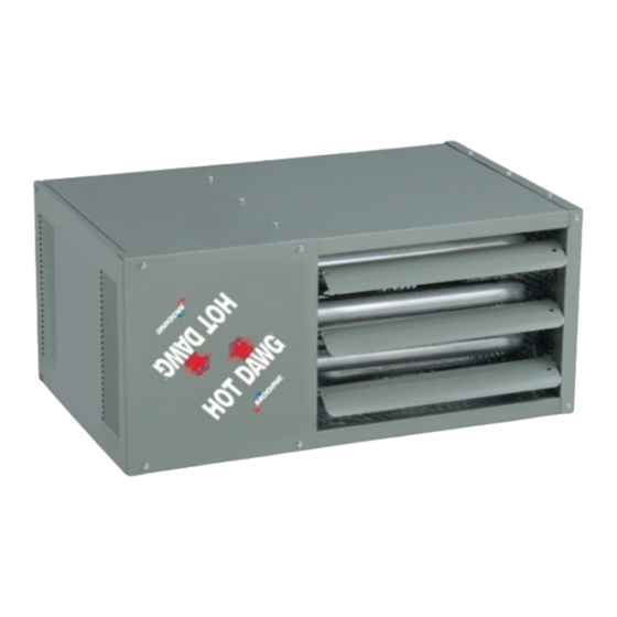
- Page 27 Unit Heater Figure 3.1 - Hot Dawg Figure 3.2 - Hot Dawg Propeller Unit Heater Blower Unit Heater Model PDP Model HD Model HDB Model PTP/BTP (BDP Not Shown) Table 3.1 - Standard Features and Factory Options j Model Feature...
-
Page 28: Design Features - Model Hd/Hdb
DESIGN FEATURES - MODELS HD/HDB Figure 4.1 - Factory Mounted Standard and Optional Features (Models HD/HDB) j Power Exhauster (STD) n Control Step Down Transformer - (STD) All HD series (low profile) unit heaters are supplied with a The control step down transformer is located in the round vent pipe connection . -
Page 29: Design Features - Model Pdp/Bdp
DESIGN FEATURES - MODELS PDP/BDP Figure 5.1 - Factory Mounted Standard and Optional Features (Models PDP/BDP) All units include the standard (STD) features, and may include n Control Step Down Transformer - (STD) the optional (OPT) features shown . The control step down transformer is located in the electrical junction box . -
Page 30: Design Features - Model Ptp/Btp
DESIGN FEATURES - MODELS PTP & BTP Figure 6.1 - Factory Mounted Standard and Optional Features (Model PTP) Rear of Unit j Power Exhauster (STD) electrical junction box . The transformer is used to step down the supply power (115V, 208V, 230V, 460V, 575V) to 24V for All PTP series unit heaters are supplied with a round vent the gas controls, fan delay relay, field supplied motor starter, pipe connection . - Page 31 GENERAL PERFORMANCE DATA - MODELS HD & PDP Table 7.1 - Propeller Unit Model HD and PDP General Performance Data Model HD Sizes Model PDP Sizes Btu/Hr Input j 30,000 45,000 60,000 75,000 100,000 125,000 150,000 175,000 200,000 250,000 300,000 350,000 400,000...
- Page 32 GENERAL PERFORMANCE DATA - MODEL PTP & BTP Table 8.1 - Model PTP and BTP General Performance Data Model PTP Sizes Model BTP Sizes Btu/Hr Input 150,000 175,000 200,000 250,000 300,000 350,000 400,000 150,000 175,000 200,000 250,000 300,000 350,000 400,000 Btu/Hr Ouput 123,000 143,500 166,000 207,500 249,000 290,500 332,000 123,000 143,500 164,000 205,000 246,000 287,000 328,000 Entering Airflow...
- Page 33 GENERAL PERFORMANCE DATA - MODEL PTP & BTP Table 9.1 - Blower Model BTP Motor Amp Draw m n Supply Voltage Motor HP 115V/1ph 230V/1ph 208V/3ph 230V/3ph 460V/3ph 575V/3ph 3 .70 5 .00 2 .50 1 .60 1 .40 .70 0 .60 7 .20 3 .60...
- Page 34 BLOWER PERFORMANCE DATA - MODEL BTP Table 10.1 - Power Code Description - Blower Model BTP j BTP150 BTP175 BTPS250 BTP300 BTP350 BTP400 Power Code Voltage Phase Drive Drive Drive Drive Drive Drive 115/230 1 1/2 1 1/2 208-230/460 1 1/2 1 1/2 1 1/2 1 1/2...
- Page 35 BLOWER PERFORMANCE DATA - MODEL BTP Table 11.1 - Blower Model BTP 150-250 (40-55°F temp rise for 250 size unit) j k l External Static Pressure (“W.C.) Model RPM Drive Turns RPM Drive Turns RPM Drive Turns RPM Drive Turns RPM Drive Turns RPM Drive Turns RPM Drive Turns RPM Drive Turns HP ATR CFM Table 11.2 - Size...
- Page 36 BLOWER PERFORMANCE DATA - MODEL BTP Table 12.1 - Blower Model BTP 250-400 (60-70°F temp rise for 250 size unit) j k l External Static Pressure ("W.C.) Model Size ATR CFM RPM Drive Turns RPM Drive Turns RPM Drive Turns RPM Drive Turns RPM Drive Turns RPM Drive Turns RPM Drive Turns RPM Drive Turns HP Table 12.2 - 4 .0 3 .0...
- Page 37 GENERAL PERFORMANCE DATA - MODELS HDB & BDP Table 13.1 - Blower Unit Model HDB and BDP General Performance Data Model HDB Sizes Model BDP Sizes Btu/Hr Input j 60,000 75,000 100,000 125,000 150,000 175,000 200,000 250,000 300,000 350,000 400,000 Btu/Hr Ouput j 49,200 61,500...
- Page 38 BLOWER PERFORMANCE DATA - MODEL HDB Table 14.1 - Power Code Description - HDB Models Power Code Unit Voltage HDB60 HDB75 HDB100 HDB125 115/60/1 1/4 HP 1/3 HP 1/2 HP 1/2 HP Blower Speed Curves Models (HDB 60-125) Medium High HDB 60 HDB 100 1140...
- Page 39 BLOWER PERFORMANCE DATA - MODEL BDP Table 15.1 - Power Code Description — Blower Model BDP j Power Code Voltage Phase Drive Drive Drive Drive Drive Drive Drive 208-230/460 1-1/2 1-1/2 1-1/2 208-230/460 1-1/2 1-1/2 1-1/2 1-1/2 208-230/460 1-1/2 1-1/2 1-1/2 1-1/2 1-1/2...
- Page 40 BLOWER PERFORMANCE DATA - MODEL BDP Table 16.1 - Models With or Without Blower Enclosure - Blower Model BDP j k 0.0” Static Press. 0.1” Static Press. 0.2” Static Press. 0.3” Static Press. 0.4” Static Press. Model Size Drive Turns RPM Drive Turns RPM Drive Turns RPM Drive Turns RPM...
- Page 41 BLOWER PERFORMANCE DATA - MODEL BDP Table 17.1 - Models With or Without Blower Enclosure - Blower Model BDP j k Filters Data for use with filters only For blower units with enclosure and filter, add the 0.5” Static Press. 0.6”...
-
Page 42: Gas Control Data - All Models
Motor Starter Model Phase Voltage (Control & Mtr) Required (Order Separate) Available Transformer Coil Voltage none 208V to 115V HD/HDB/ 230V to 115V 115V/1ph 11,12,21,22 115V to 24V none 1 or 3 460V to 115V 575V to 115V PDP/BDP none... -
Page 43: Field Installed Accessories
ACCESSORIES Table 19.1 - Field Installed Accessories Model Feature Vertical Deflector Blades - Allows directional discharge air control in the left and right • • • • • • directions . Downward Air Deflector Hoods - Available in 30°, 60°, and 90° configurations these deflector hoods enable the unit to be mounted higher while still providing heat to the building •... - Page 44 PERFORMANCE DATA - HOODS FOR PROPELLER MODELS Table 20.1 - Downtown Hood General Performance Data for HD/PDP/PTP (feet) Model HD Sizes Model PDP Sizes Model PTP SIzes Max. Mtg. Height (ft.) 30° Hood 60° Hood 90° Hood Figure 20.1 - 30°, 60°, and 90° Downward Deflector Hoods Figure 20.2 - 30°...
- Page 45 PERFORMANCE DATA - HOODS FOR BTP/BTS BLOWER MODELS Table 21.1 - Deflector Hood General Performance Data - Model BTP/BTS 30° Hood 60° Hood 90° Hood Temp Mounting Blade Airflow Model Rise Height Angle Size (cfm) (°F) (ft) (°) (ft) (ft) (ft) (ft) (ft) (ft) (ft) 2020 2357...
- Page 46 PERFORMANCE DATA - VELOCITY GENERATING NOZZLES Figure 22.1 - Velocity Generating Nozzles 40° DOWNWARD 90° VERTICAL NOZZLE NOZZLE 5-WAY NOZZLES 40° SPLITTER NOZZLE j Velocity generating nozzles available for Blower Model BDP only . Table 22.1 - Blower Unit Model BDP Velocity Generating Nozzle Performance Data (feet) BDP Blower Model Size Nozzle Type...
-
Page 47: Unit Selection
UNIT SELECTION Selection Procedure With this information a basic unit can be selected as shown in the following example . In order to properly select a unit heater it is necessary to have the following basic information . Selection Example Conditions (Propeller Unit) 1. - Page 48 UNIT SELECTION Selection Example Conditions (Blower Unit) In the following example, select a unit heater to meet the following conditions: 1 . Heating output capacity = 156,000 Btu/Hr per design engineer 2 . External Static Pressure = 0 .2 . 3 .
-
Page 49: Dimensional Data - Models Hd/Hdb
10 - 10 Approx . Shipping Weight (lbs .) Approx .Shipping Weight (lbs .) Vent Pipe Connector Vent Pipe Connector Diameter (in) Diameter (in) Table 25.3 - Clearance to Combustibles, Model HD/HDB Clearance to Combustible Recommended Service Unit Side Material Clearance HD/HDB Top and Bottom 1"... -
Page 50: Dimensional Data - Model Pdp
DIMENSIONAL DATA - MODEL PDP Propeller Units - Model PDP Figure 26.1 - Dimensional Drawings D (OPENING) (MIN. DISTANCE TO WALL) Figure 26.2 - Combustible Material and Table 26.1 - Dimensions (inches) - PDP j Service Clearances Dimension Model Number Symbol PDP 150 PDP 175 PDP 200 PDP 250 PDP 300 PDP 350 PDP 400 23-1/2... -
Page 51: Dimensional Data - Model Bdp
DIMENSIONAL DATA - MODEL BDP Blower Units - Model BDP Figure 27.1 Dimensional Drawings " " " Q x V R x T " BLOWER FILTER RACK D (OPENING) M (APPROX.) ENCLOSURE (OPTIONAL) (OPTIONAL) L (MIN. DISTANCE TO WALL) L (MIN. DISTANCE TO WALL) Table 27.1 - Dimensions (inches) - BDP Figure 27.2 - Combustible Material and Service Clearances... -
Page 52: Dimensional Data - Model Ptp
DIMENSIONAL DATA - MODEL PTP Propeller Units - Model PTP Figure 28.1 - Dimensional Drawings Table 28.1 - Dimensions (inches) - PTP j Models PTP150 PTP175 PTP200 PTP250 PTP300 PTP350 PTP400 35 .53 42 .53 42 .53 42 .53 42 .53 42 .53 42 .53 23 .06... -
Page 53: Dimensional Data - Model Btp
DIMENSIONAL DATA - MODEL BTP Figure 29.1 - Dimensional Drawings - Model BTP BLOWER ENCLOSURE 6 MOUNTING (OPTIONAL) 4 7/8" HOLES FILTER RACK 7/8" (OPTIONAL) 4.88 ADJUSTABLE LOUVERS O x P OPENING M (APPROX.) Q (MIN DIST TO WALL) Table 29.1 - Dimensions (inches) — BTP Models BTP150 BTP175 BTP200 BTP250 BTP300 BTP350 BTP400 35 .53... -
Page 54: Specifications - All Models
E .1 .a . The heat exchanger(s) shall be made of 18 gauge aluminized F .4 . A contractor convenience junction box with unit on/off switch, steel (opt 409 stainless steel) . (HD/HDB/PTP models) terminal board for low voltage wiring, and system status indicator light (PTP/BTP models) The thermal efficiency of the unit(s) shall be a minimum of 82-83% for all air flow ranges . - Page 55 . The stat shall also include switching for Heat/Off and threaded rod suspension or to be bolted directly to the ceiling Fan On/Auto control . support structure allowing 1" of top clearance . (HD/HDB models - opt on sizes 100/125) K .4 .
- Page 56 Figure 32.1 - Model Number Designations PDP 200 Factory Installed Option Digit Unit Con guration N - None HD - Tubular Power Vented Propeller Unit HDB - Tubular Power Vented Blower Unit PDP - Propeller Unit Power Vent Future BDP - Blower Unit Power Vent...
- Page 57 THIS PAGE INTENTIONALLY LEFT BLANK 6-189.18...
- Page 58 THIS PAGE INTENTIONALLY LEFT BLANK 6-189.18...
- Page 59 THIS PAGE INTENTIONALLY LEFT BLANK 6-189.18...
- Page 60 Specific catalogs are available for each product . Catalogs 75-136 and 75-137 provide details on all Modine HVAC equipment . ® Modine Manufacturing Company 1500 DeKoven Avenue Racine, Wisconsin 53403-2552 Phone: 1 .800 .828 .4328 (HEAT) www .modinehvac .com © Modine Manufacturing Company 2022...
- Page 61 9-512 December 2020 INSTALLATION AND SERVICE MANUAL High Intensity Gas Fired Infrared Unit Heaters Model IHR, Control Codes 47, 48, 97, 98, 27, and 67 INSTRUCTIONS APPLY TO: Installation Operation Maintenance HAZARD INTENSITY LEVELS WARNING • DANGER: Failure to comply will result in severe Improper installation, adjustment, alteration, personal injury or death and property damage service, or maintenance can cause property...
- Page 62 IHR Series Manual Contents 1.0 Safety..............3 Safety Symbols .
-
Page 63: Safety
IHR Series Manual Safety • Safety Symbols • Applications Safety WARNING Improper installation, adjustment, alteration, service, or maintenance can cause property damage, serious injury, or death. Read and understand the installation, operating, and maintenance instructions thoroughly before installing or servicing this heater. Only trained, qualified gas installation and service personnel may install or service this heater. -
Page 64: Clearances To Combustibles
IHR Series Manual Safety • Clearances to Combustibles Clearances to Combustibles WARNING Placement of explosive objects, flammable objects, liquids, and vapors close to the heater may result in explosion, fire, property damage, serious injury, or death. Do not store or use explosive objects, liquids, or vapors in the vicinity of the heater. - Page 65 IHR Series Manual Safety • Clearances to Combustibles Chart 1.1 • Clearances to Combustibles in Inches (see Figure 1.1) Model No. Sides Back Below/Front IHR 30 IHR 60 IHR 90 IHR 130 IHR 160 * This clearance is 80 in. when the heater is fitted with a parabolic reflector. NOTE: If the heater is mounted beneath a non-combustible surface, a 24 in.
-
Page 66: Gas Connection
Safety IHR Series Manual • Gas Connection • Standards, Certifications, and Government Regulations Gas Connection WARNING An approved connector, suitable for the environment of heater usage, is required. Visible or excessive swaying, flexing, and vibration of the gas connections must be avoided to prevent failure. - Page 67 IHR Series Manual Safety • Standards, Certifications, and Government Regulations Chart 1.3 • Standards and Code Installation Guidelines • Building Type Building Codes and Guidelines Aspect Public Installation of this infrared heater in public garages must conform to the following Garages codes: United States: Standard for Parking Structures NFPA 88A (latest edition) or the...
-
Page 68: Safety Labels And Their Locations
2011MODIXXXXXX 0001 DEGREES DEGREES DESIGN COMPLIES WITH: ANSI Z83.19-2017/CSA 2.35-2017 Gas-Fired High Intensity Infrared Heater MODINE MANUFACTURING COMPANY FOR COMMERCIAL AND INDUSTRIAL USE ONLY NOT FOR RESIDENTIAL USE 1500 DEKOVEN AVENUE - RACINE, WI 53403 MADE IN USA 1.800.828.4325 (HEAT) www.modinehvac.com... -
Page 69: Installation
IHR Series Manual Installation • Design Installation WARNING Read and understand the installation, operating, and maintenance instructions thoroughly before installing or servicing this heater. Only trained, qualified gas installation and service personnel may install or service this heater. CAUTION This heater cannot be used in a building with an uninsulated roof or condensation problems can occur. Design To ensure a safe, properly designed heating system, a layout should be developed for the correct placement of the infrared heater(s). - Page 70 Factory recommended mounting heights are listed as a guideline. If infrared heaters are mounted too low or too high, they may result in discomfort or lack of heat. Modine Manufacturing Company generally recommends observing the recommended mounting heights to optimize comfort conditions. However, certain applications such as spot heating, freeze protection, outdoor patio heating, or very high ceilings may result in the heaters being mounted outside of the recommended mounting heights.
-
Page 71: Heater Placement
IHR Series Manual Installation • Heater Placement Chart 2.2 • Recommended Mounting Heights and Distances for “Spot” Heating Distance Recommended Behind Centers for Mounting Height Approx. Approx. Person or Full Coverage Stnd. Reflector Model Type of Area Area Coverage Work Station (Spot &... -
Page 72: Heater Mounting
Installation IHR Series Manual • Heater Mounting Heater Mounting WARNING Improper suspension of the infrared heater may result in collapse and being crushed. Always suspend from a permanent part of the building structure that can support the total force and weight of the heater. Failure to maintain minimum clearances to combustibles may result in fire and/or explosion, property damage, serious injury, or death. -
Page 73: Ventilation
IHR Series Manual Installation • Ventilation Ventilation WARNING Insufficient ventilation may result in health problems, carbon monoxide poisoning, or death. Vent enclosed spaces and buildings according to national, state, provincial, and local codes. Improper venting may result in asphyxiation, fire, explosion, injury, or death. It is required that the levels where heaters are mounted be properly ventilated to supply combustion air to the heaters and to sufficiently dilute the products of combustion. -
Page 74: Gas Supply
Installation IHR Series Manual • Gas Supply Gas Supply WARNING Improperly connected gas lines may result in fire, explosion, poisonous fumes, toxic gases, asphyxiation, or death. Connect gas lines in accordance to national, state, provincial, and local codes. The gas supply to the infrared heater must be connected and tested in accordance with national, state, provincial, and local codes along with the guidelines in the this manual. - Page 75 IHR Series Manual Installation • Gas Connection To connect the gas: WARNING Failure to install, operate, or service this heater in the approved manner may result in property damage, injury, or death. An approved connector, suitable for the environment of heater usage, is required. Visible or excessive swaying, flexing, and vibration of the gas connections must be avoided to prevent failure.
-
Page 76: Leak Testing
Installation IHR Series Manual • Gas Connection • Leak Testing Figure 2.5 • Gas Connection NOTE: Use a Disconnect switch TOP VIEW regulator when gas supply pressure exceeds 14” W.C. Do not exceed 14” W.C. to the appliance. Drip Leg/ Sediment Trap 20˚... -
Page 77: Electrical Requirements And Wiring Diagrams
IHR Series Manual Installation • Electrical Requirements and Wiring Diagrams Electrical Requirements and Wiring Diagrams WARNING Shock hazard. Disconnect power supply before making wiring connections to prevent electrical shock and equipment damage. Any original factory wiring that requires replacement must be replaced with wiring material having a rating of at least 600 V, 105°C. All field installed wiring to the unit heater must be must be done in accordance with the national, state, provincial, local codes, and to the guidelines in this manual. - Page 78 Installation IHR Series Manual • Wiring Diagrams Figure 2.7 • Millivolt • 750 Schematic • Millivolt Control N/PFS-2 24VAC Figure 2.8 • 24 V Schematic • Direct Spark (24VAC) Ignition ELECTRODE • VA Draw: 12 ASSEMBLY • Amps: .48 SENSE •...
-
Page 79: Operation
IHR Series Manual Operation • Lighting Instructions Operation WARNING Do not attempt to ignite a direct spark ignition heater by hand. Failure to comply could result in personal injury, property damage, explosion, fire, or death. Upon satisfactory completion of the electrical supply and purging of the gas supply line to the heater(s), follow the lighting instructions on the heater’s rating label to put the heater into operation. -
Page 80: Maintenance
Maintenance • IHR Series Manual Maintenance Checks Maintenance It is recommended that the following become a standard yearly procedure to obtain maximum operating efficiency and trouble free operation. During long periods of non-usage, remove or cover heater with a polyethylene bag and shut off gas supply. If further service to the heater is desired, contact your representative or the factory. -
Page 81: Troubleshooting Guide
IHR Series Manual Maintenance • Troubleshooting Chart 4.1 Troubleshooting Guide • Symptom Code Possible Cause Corrective Action Burning of gas-air A, B • Heater mounted at incorrect angle. • Mounting angle 20°-35° from horizontal. mixture inside A, B • Excessive drafts. •... -
Page 82: Heater Assembly Components
Maintenance IHR Series Manual • Heater Assembly Components Heater Assembly Components NOTE: Replacement burners are called “rayheads” with rod inserts. Ceramic grids are not sold separately. Figure 4.1 • Heater Assembly Components Figure 4.2 • Heater Assembly Components (side view) (rear view of Direct Spark) Cross-over Heat Shield... -
Page 83: Parts Listing
IHR Series Manual Maintenance • Parts Listing Parts Listing IMPORTANT: Contact factory for conversion assistance. Note: Gas type conversions require gas valve and gas orifice(s) among other changes. Conversion may also require burner and crossover changes. • Chart 4.2 Direct Spark Control Components Voltage Part No. -
Page 84: Limited Warranty
Burners High Intensity INfrared Units Sheet Metal Parts All Prodcuts As Modine Manufacturing Company has a continuous product improvement program, it reserves the right to change design and specifications without notice. Modine Manufacturing Company 1500 DeKoven Avenue Racine, WI 53403 Phone: 1.800.828.4328 (HEAT) - Page 85 HEATING SOLUTIONS GARAGE, WORKSPACE AND OUTBUILDING HEATERS...
- Page 86 * Included on sizes 30-75, accessory for 100, 125 ** For model sizes 30-75 DAWG SEPARATED COMBUSTION ™ GAS-FIRED UNIT HEATER (MODEL HDS) Experience the same great features as the HD, with these added benefits: Factory assembled, certified separated Blower models (HDB) available • •...
- Page 87 16” or 24” centerlines. Btu/Hr Output 24,000 36,000 48,000 60,000 80,000 100,000 Approx. Shipping Weight (lbs.) 1,160 1,490 1,980 Entering Air ow (CFM) * 3" for Model HD, 4" for Model HDS Outlet Velocity SIZES Clearances 30-75 Air Temp. Rise (°F)
- Page 88 Modine Manufacturing Company 1500 DeKoven Avenue Racine, Wisconsin 53403-2552 1.800.828.HEAT www.ModineHVAC.com ©2018 Modine Manufacturing Co. 6-114.10...
-
Page 89: Inspection On Arrival
January, 2023 INSTALLATION AND SERVICE MANUAL gas-fired unit heaters model HD and HDB All models approved for use in California by the CEC and in Massachusetts. Unit heater is certified for residential and commercial applications. These unit heaters are certifed as Utility... -
Page 90: Special Precautions
SPECIAL PRECAUTIONS SPECIAL PRECAUTIONS CAUTION THE INSTALLATION AND MAINTENANCE INSTRUCTIONS IN THIS MANUAL MUST BE FOLLOWED TO PROVIDE SAFE, EFFICIENT, AND TROUBLE-FREE OPERATION. IN ADDITION, PARTICULAR CARE 1. All literature shipped with this unit should be kept for MUST BE EXERCISED REGARDING THE SPECIAL PRECAUTIONS future use for servicing or service diagnostics. -
Page 91: Si (Metric) Conversion Factors
SPECIAL PRECAUTIONS / SI (METRIC) CONVERSION FACTORS BEFORE YOU BEGIN CAUTION CAUTION 17. When leak testing the gas supply piping system, the appliance and its combination gas control must be isolated 1. All literature shipped with this unit should be kept for future during any pressure testing in excess of 14"... -
Page 92: Unit Location
If the installation requires the controls to be atmosphere. on the right side, all heaters - with the exception of the HD/HDB 100 and 125 - can be turned over by following the instructions Location Recommendations below. -
Page 93: Unit Mounting
UNIT MOUNTING Figure 5.2 - Unit Heater Turned 180° CAUTION (30-75 units only) (Access panel and heated air outlet change sides) 1. Do not install units below 7' measured from the bottom of the unit to the floor in commercial applications (unless unit is properly guarded to provide user protection from moving parts) and 5' measured from the bottom of the unit to the floor in residential applications. - Page 94 A9. Avoid venting through unheated space when possible. When venting does pass through an unheated space or Model HD/HDB unit heaters must be vented with the proper if the unit is installed in an environment that promotes passageway as described in these instructions to convey...
- Page 95 INSTALLATION - VENTING diameter is necessary. If there is 6' or more of vent pipe in A18. In addition to following these general instructions, specific the open space between the appliance and where the vent instructions for Vertical Category I or Horizontal Category III pipe passes through the wall or floor, the thimble need only vent systems must also be followed.
- Page 96 INSTALLATION - VENTING Figure 8.1 - Vertical Vent Termination for Double Section B – Vertical Vent System Installation Wall Vent Pipe and Greater Than or Less Than 8’ B1. This section applies to vertically vented Category I Horizontally From a Vertical Wall or Obstruction vent systems and is in addition to “Section A –...
- Page 97 INSTALLATION - VENTING • For single wall vent pipe and 10' or greater horizontal • For single wall vent pipe and less than 10' horizontal distance distance to any portion of a building, the vent must terminate at to any portion of a building, the vent must terminate 2' higher least 3' (2' for non-residential installations) above the highest than any portion of that building (see Figure 9.2).
- Page 98 INSTALLATION - VENTING Section C – Horizontal, Category III Vent System C6. The venting system must be exclusive to a single unit, and Installation no other unit is allowed to be vented into it. C1. This section applies to horizontally vented Category III Figure 10.2 - Horizontal Category III Venting with vent systems and is in addition to “Section A –...
- Page 99 INSTALLATION - VENTING Additional Requirements for Common Venting: Table 11.1 - Maximum Vent Connector Horizontal Run (ft) - Type B Vent Connector 1. The common vent system and all attached appliances must be Category I. Connector 2. The vent connector should be routed in the most direct Model Max Horiz.
-
Page 100: Gas Connections
INSTALLATION - GAS CONNECTIONS Figure 12.1 - Recommended Sediment Trap/Manual WARNING Shut-off Valve Installation - Side or Bottom Gas Connection 1. All field gas piping must be pressure/leak tested prior to operation. Never use an open flame. Use a soap solution or equivalent for testing. -
Page 101: High-Altitude Accessory Kit
INSTALLATION - HIGH ALTITUDE ACCESSORY KIT HIGH ALTITUDE ACCESSORY KIT Manifold Pressure Adjustment The inlet pressure to the unit must be confirmed to be within Modine’s gas-fired equipment standard input ratings are acceptable limits (6-7" W.C. for natural gas and 11-14" W.C. certified by ETL. - Page 102 INSTALLATION - HIGH ALTITUDE ACCESSORY KIT Table 13.3 - High Altitude Kits for HD/HDB If the heating value of the gas being supplied is different than the values shown in Tables 13.1 and 13.2, use the following Model Size equation to determine the appropriate manifold pressure for the US and Canada altitude and gas heating value being supplied.
- Page 103 INSTALLATION - ELECTRICAL CONNECTIONS ELECTRICAL CONNECTIONS W ARNING 1. Disconnect power supply before making wiring connections to prevent electrical shock and equipment damage. 2. All appliances must be wired strictly in accordance with wiring diagram furnished with the appliance. Any wiring different from the wiring diagram could result in a hazard to persons and property.
-
Page 104: Electrical
INSTALLATION - ELECTRICAL CONNECTIONS ELECTRICAL CONNECTIONS Blower Curve Models (HDB 60-125 Only) Location of thermostat should be determined by heating Speeds requirements and be mounted on an inside wall about 5' above floor level where it will not be affected by heat from the unit Medium High or other sources, or drafts from frequently opened doors. -
Page 105: Operation
INSTALLATION - OPERATION OPERATION 10. Turn on power to the unit at the disconnect switch. 11. Check the thermostat, ignition control, gas valve, and supply Prior to Operation fan blower motor for electrical operation. If these do not IMPORTANT function, check that the wiring is per the diagram. 12. -
Page 106: Unit Components
Firing rate is 100% and 50% of full rated input. Gas is lit with a direct spark 115V Propane 75-125 igniter on call for heat. Table 18.2 - Propeller Model HD Performance Table 18.3 - Blower Model HDB Performance Model HD Sizes Model HDB Sizes Btu/Hr Input Btu/Hr Input ... -
Page 107: Dimensions
18.0 Approx.Shipping Weight (lbs.) Approx. Shipping Weight (lbs.) Vent Connector Size (in) Vent Connector Size (in) Table 19.3 - Clearance to Combustibles, Model HD/HDB Figure 19.3 - Mounting Clearance to Combustible Recommended Service Mounting brackets are slotted to accomodate joists on 16" or 24" centerlines. - Page 108 SERVICE / MAINTENANCE / TROUBLESHOOTING 1. Service air moving components annually. WARNING a. Check fan for fit on motor shaft and for damage to blades. 2. Keep unit free from dust, dirt, grease, and foreign matter, When servicing or repairing this equipment, use only factory- paying particular attention to: approved service replacement parts.
- Page 109 UNIT WIRING Wiring Diagram Selection Since internal or factory wiring may vary depending on type. The following wiring diagram represents a unit equipped the controls manufacturer, the wiring diagrams must be with a single or two stage gas valve and direct spark ignition. appropriately selected with the proper gas valve and ignition Figure 21.1 - Unit Heater Wiring Diagram (Single and Two Stage, Direct Spark Ignition) GR, (G)
- Page 110 MODEL & SERIAL NUMBER / REPLACEMENT PARTS Figure 22.1 - Model Number Designations (Remove access cover to locate) HD - Tubular Power Vented Factory Installed Option Digit Propeller Unit N - None HDB - Tubular Power Vented Blower Unit Future...
- Page 111 THIS PAGE INTENTIONALLY LEFT BLANK 6-583.15...
-
Page 112: Commercial Warranty
Burners High Intensity Infrared Units Sheet Metal Parts All Products As Modine Manufacturing Company has a continuous product improvement program, it reserves the right to change design and specifications without notice. Modine Manufacturing Company 1500 DeKoven Avenue Racine, WI 53403 Phone: 1.800.828.4328 (HEAT) - Page 137 Hot Dawg ® Troubleshooting Guide...
- Page 138 Troubleshooting Hot Dawg Direct Spark Units ® IMPORTANT WARNING 1. Improper installation, adjustment, The use of this manual is specifically intended for a qualified installation and alteration, service or maintenance service agency. All installation and service of can cause property damage, injury or death and could cause exposure these units must be performed by a qualified to substances which have been...
-
Page 139: Introduction
Introduction The purpose of this handbook is to help you troubleshoot through any problems that might come up when installing or servicing your Modine Hot Dawg unit heater. ® Definitions Soft Lockout of Control: The control does not initiate a call for continuous fan while in lockout. -
Page 140: Flame Status - Yellow Led Labeled "Flame
Flame Status – Yellow LED Labeled “Flame” Flame status LED is lit when flame is sensed. Flame LED flashes slowly when flame current is below 1.0uA (+/- 50%), to indicate a “weak” flame. Flame LED flashes fast when flame is present with gas valve off. •... -
Page 141: Heating Sequence Of Operation
Heating Sequence of Operation Listed below is the sequences of operation that occurs when there is a call for heat: • The green LED will be on at all times. It only flashes during a fault. • Thermostat contacts close board terminals R & W together •... -
Page 142: Thermostat Connections
Thermostat Connections Listed below are typical residential thermostat connections to the Hot Dawg ® control board. Consult thermostat manufacturer’s instructions for more details. • T-stat terminal R (required) - Connects to board terminal R for a 24 VAC source • T-stat terminal W (required) - Connects to board terminal W to call for heat •... -
Page 143: Call For Heat - Unit Does Nothing
Call for Heat – Unit Does Nothing The below troubleshooting steps refer to situations where the green light on the control board is ON: Step 1: Verify that the thermostat is wired correctly and there is a call for heat. Step 2: Verify that the thermostat is wired between the R &... - Page 144 Call for Heat – Unit Does Nothing The below troubleshooting steps refer to situations where the green light on the control board is ON and the unit does NOT operate correctly when a jumper wire is installed between terminals R & W on the control board: Step 1: Check for loose connections.
- Page 145 Call for Heat – Unit Does Nothing The below troubleshooting steps refer to situations where the green light on the control board is OFF: Step 1: If the green light on the control board is off, verify there is not a flash code. Step 2: Verify that there is 24 VAC between Sec &...
- Page 146 Call for Heat – Unit Does Nothing The below troubleshooting steps refer to situations where the green light on the control board is OFF and 24 VAC is NOT present between Sec & Com on board: Step 1: Check for loose connections. Step 2: Check incoming power (115 VAC).
- Page 147 No Flashes – Troubleshooting Codes The below troubleshooting information is related to situations where there are NO flashes: • If there is no flash code, please refer to page 8, and follow the troubleshooting steps.
- Page 148 One Flash – No Power Exhauster The below troubleshooting information is related to situations where the power exhauster does not cycle on: • When there is a ONE flash troubleshooting code, the unit is indicating that the pressure switch is not closing within 30 seconds of the power exhauster being energized.
- Page 149 One Flash – Pressure Switch Won’t Close The below troubleshooting information is related to situations where the power exhauster DOES cycle on: Unit Sequence: Green light on, call for heat, 24 VAC at R & W, power exhauster cycles on after approximately 30 seconds, Green light will give one flash. •...
- Page 150 Two Flashes – Pressure Switch Closes Before Power Exhauster Energizes When there is a TWO flash troubleshooting code, the unit is indicating that the pressure switch has closed before the power exhauster is energized. Troubleshooting Steps: 1. Pull one of the yellow wires off the pressure switch. If the power exhauster turns on and the code goes away, replace the switch.
- Page 151 Three Flashes – Open in the Safety Switch Circuit When there is a THREE flash troubleshooting code, the unit is indicating that the limit switch or flame roll out switch is open. • The limit switch is ignored unless a call for heat is present (R to W energized). •...
- Page 152 Four Flashes – Unit Sparks, Lights Flame and Shuts Down After 10 Seconds The information below is related to situations where the unit DOES SPARK and then SHUTS DOWN within 10 seconds: This usually occurs as a result if the safety switch circuit is open: •...
- Page 153 Four Flashes – Unit in Lockout From Failed Ignition/ Flame Loss – Unit Sparks but Doesn’t Ignite The information below is related to situations where the unit is in lockout from failed ignition or flame loss. The unit sparks but DOES NOT IGNITE: Unit Sequence: •...
- Page 154 Four Flashes – Unit Doesn’t Spark The information below is related to situations where the unit is in lockout from failed ignition or flame loss and the unit DOES NOT SPARK: Unit Sequence: • Green light on, call for heat •...
- Page 155 Five Flashes – Twin Communication Fault The information below is related to situations where the troubleshooting code flashes FIVE times: Twin Communication Fault: • Occurs if the 24 VAC supply to the twins are not in phase with each other or power is removed from one of the twins.
- Page 156 Six Flashes – Main Air Mover Doesn’t Cycle On The information below is related to situations where the main air mover DOES NOT cycle on: This usually occurs as a result of an open in the safety switch circuit: • Limit switch or flame roll out switch is open Unit Sequence: •...
- Page 157 Six Flashes – Main Air Mover Does Cycle On The information below is related to situations where the main air mover DOES cycle on: Unit Sequence: • Green light on, call for heat, power exhauster cycles on, fan motor cycles on, green light flashes six times Possible Causes: •...
- Page 158 Seven Flashes – Five Flame Losses During One Heat Cycle The information below is related to situations where there are five flame losses during one heat cycle. If this occurs, you will see a troubleshooting code for SEVEN flashes: Ignition Re-cycle: •...
-
Page 159: Before Replacing A Control Board
Before Replacing a Control Board • Remove thermostat and use a temporary jumper wire to make a call for heat • Check the supply power for correct polarity • Re-check all wiring to the control board for loose connections: – Disconnect and reconnect all Molex plugs •... - Page 160 In addition, Modine has live operators That can be reached at: (800)-828-4328 Scan the QR code for a mobile- friendly version of this guide Modine Manufacturing Company 1500 DeKoven Avenue @ModineHVAC Racine, Wisconsin 53403-2552 YouTube.com/ModineHVAC ©2021 Modine Manufacturing Co www.facebook.com/ModineHVAC 6-549.1 www.linkedin.com/company/modinehvac...
-
Page 161: Inspection On Arrival
6-580.18 5H0782130000 January, 2023 INSTALLATION AND SERVICE MANUAL power vented gas-fired unit heaters models PDP and BDP All models approved for use in California by the CEC and in Massachusetts. Unit heater is certified for non-residential applications. FOR YOUR SAFETY The use and storage of gasoline or other flammable vapors and liquids in open containers in the vicinity of this appliance is hazardous. -
Page 162: Special Precautions
SPECIAL PRECAUTIONS W ARNING SPECIAL PRECAUTIONS 12. When servicing or repairing this equipment, use only THE INSTALLATION AND MAINTENANCE INSTRUCTIONS IN factory-approved service replacement parts. A complete THIS MANUAL MUST BE FOLLOWED TO PROVIDE SAFE, replacements parts list may be obtained by contacting EFFICIENT AND TROUBLE-FREE OPERATION. -
Page 163: Si (Metric) Conversion Factors
SPECIAL PRECAUTIONS / SI (METRIC) CONVERSION FACTORS BEFORE YOU BEGIN CAUTION CAUTION 15. Purging of air from gas supply line should be performed as described in the National Fuel Gas Code, ANSI Z223.1 1. All literature shipped with this unit should be kept for future (NFPA 54) - latest edition. -
Page 164: Unit Location
SI (METRIC) CONVERSION FACTORS / UNIT LOCATION UNIT LOCATION 9. Do not install units in locations where gas ignition system is exposed to water spray, rain, or dripping water. DANGER 10. Do not install units below 7', measured from the bottom of the unit to the floor, unless properly guarded to provide protection from moving parts. -
Page 165: Unit Mounting
INSTALLATION UNIT MOUNTING Figure 5.1 - Adjustable Mounting Brackets - To Adjust: 1. Be sure the means of suspension is adequate to support the weight of the unit (see pages 24 and 25 for unit weights). 2. For proper operation and to assure that flames are directed 1. - Page 166 INSTALLATION - VENTING W ARNING in Table 6.1, making the vent system as straight as possible. The equivalent length of a 5" elbow is 6' and for a 6" elbow is 7'. A5. A minimum of 12" straight pipe is recommended from the 1.
- Page 167 INSTALLATION - VENTING A10. When the vent passes through a combustible INTERIOR A16. The venting system must be exclusive to a single wall or floor, a metal thimble 4" greater than the vent appliance and no other appliance is allowed to be vented diameter is necessary.
- Page 168 INSTALLATION - VENTING Figure 8.1 - Vertical Category I Vent System Section B – Vertical Vent System Installation B1. This section applies to vertically vented Category I vent systems and is in addition to “Section A – General LISTED TERMINAL Instructions –...
-
Page 169: Installation
INSTALLATION - VENTING Section C – Horizontal, Category III Vent System Figure 9.2 - Horizontal Venting Installation with a drip leg and clean out near the exit of the vent as C1. This section applies to horizontally vented Category III shown in Figure 9.2, or allow the condensate to drip out vent systems and is in addition to “Section A –... -
Page 170: Gas Connections
INSTALLATION GAS CONNECTIONS Figure 10.1 - Recommended Sediment Trap/Manual Shut-off Valve Installation for Gas Connection WARNING 1. All field gas piping must be pressure/leak tested prior to operation. Never use an open flame. Use a soap solution or equivalent for testing. 2. -
Page 171: High-Altitude Accessory Kit
INSTALLATION - HIGH ALTITUDE ACCESSORY KIT HIGH ALTITUDE ACCESSORY KIT Manifold Pressure Adjustment The inlet pressure to the unit must be confirmed to be within Modine’s gas-fired equipment standard input ratings are acceptable limits (6-7" W.C. for natural gas and 11-14" W.C. certified by ETL. - Page 172 INSTALLATION - HIGH ALTITUDE ACCESSORY KIT Table 11.3 - High Altitude Kits for PDP/BDP If the heating value of the gas being supplied is different than the values shown in Tables 11.1 and 11.2, use the following Model Size equation to determine the appropriate manifold pressure for the US and Canada altitude and gas heating value being supplied.
- Page 173 INSTALLATION ELECTRICAL CONNECTIONS DUCT INSTALLATION IMPORTANT WARNING Do not attempt to attach ductwork of any kind to propeller 1. Disconnect power supply before making wiring connections models. to prevent electrical shock and equipment damage. 2. All appliances must be wired strictly in accordance with wiring diagram furnished with the appliance.
- Page 174 INSTALLATION rpm (see performance table for units with or without blower 3. Adjust motor adjusting screw for a belt deflection of enclosure, page 20). See “Blower Adjustments” for setting of approximately 3/4" with five pounds of force applied midway drive pulley turns open. between the sheaves (see Figure 14.3).
-
Page 175: Start-Up Procedure/Operation
START-UP PROCEDURE IMPORTANT 19. Open the field installed manual gas shut-off valve. 20. Open the manual main gas valve on the combination gas valve. Call for heat with the thermostat and allow the pilot to 1. To prevent premature heat exchanger failure, observe light for intermittent pilot ignition. - Page 176 START-UP PROCEDURE Main Burner Adjustment It may also be necessary to adjust the manifold position in addition to adjusting air shutters to obtain proper flame. Follow The gas pressure regulator (integral to the combination gas the instructions under “Natural Gas Flame Control” for adjusting control) is adjusted at the factory for average gas conditions.
- Page 177 START-UP PROCEDURE Control Operating Sequence All units are supplied with intermittent pilot systems with continuous retry control as standard. For intermittent pilot systems, both the main burner and pilot are turned off 100% when the thermostat is satisfied. For all units, the system will attempt to light the pilot for 70 seconds.
- Page 178 UNIT AND CONTROL OPTIONS Figure 18.1 - Factory Mounted Option Location All units include the standard (STD) features. The unit must be High Limit Switch - (STD) reviewed to determine the optional (OPT) features that may The automatic reset high limit switch is factory installed on have been supplied with the unit.
- Page 179 GENERAL PERFORMANCE DATA Table 19.1 - Performance - Propeller (PDP) jkl Model Number PDP 150 PDP 175 PDP200 PDP 250 PDP 300 PDP 350 PDP 400 150,000 175,000 200,000 250,000 300,000 350,000 400,000 Btu/Hr. Input Btu/Hr. Output 124,500 145,250 166,000 207,500...
- Page 180 GENERAL PERFORMANCE DATA Table 20.1 - Models With or Without Blower Enclosure - Blower Model BDP j k Alternate Drives for 575V l Drive for Drive for Model 575V Under 575V 1/4 - 191 1/4 - 197 1/3 - 191 1/3 - 197 1/3 - 95 1/3 - 96...
- Page 181 GENERAL PERFORMANCE DATA Table 21.1 - Power Code Description - Blower Model BDP j Power Code Voltage Phase Drive Drive Drive Drive Drive Drive Drive 208-230/460 1-1/2 1-1/2 1-1/2 208-230/460 1-1/2 1-1/2 1-1/2 1-1/2 208-230/460 1-1/2 1-1/2 1-1/2 1-1/2 1-1/2 1-1/2 1-1/2 208-230/460...
- Page 182 PERFORMANCE DATA - HOODS Table 22.1 - Performance Data - 30°, 60° and 90° Downward Deflector Hoods 30° Downward Hood For Propeller Units Mounting Height Bottom BDP 150 BDP 175 BDP 200 BDP 250 BDP 300 BDP 350 BDP 400 PDP 150 PDP 175 PDP 200...
- Page 183 PERFORMANCE DATA – NOZZLES Figure 23.1 - Mounting Height, Heat Throw, Heat Spread (in feet) 90° VERTICAL NOZZLE 40° DOWNWARD NOZZLE 5-WAY NOZZLES 40° SPLITTER NOZZLE Table 23.1 - Mounting Height, Heat Throw, Heat Spread (in feet) Model Number Nozzle Type BDP 150 BDP 175 BDP 200 BDP 250 BDP 300 BDP 350 BDP 400 Max.
- Page 184 DIMENSIONAL DATA Figure 24.1 Dimensional Drawings - Propeller Units (Model PDP) D (OPENING) (MIN. DISTANCE TO WALL) Table 24.1 - Dimensions (inches) - PDP Dimension Model Number Symbol PDP 150 PDP 175 PDP 200 PDP 250 PDP 300 PDP 350 PDP 400 23-1/2 25-5/8 25-5/8...
-
Page 185: Dimensions
DIMENSIONAL DATA Figure 25.1 - Dimensional Drawings - Blower Units (Model BDP) D (OPENING) (MIN. DISTANCE TO WALL) Table 25.1 - Dimensions (inches) - BDP Model Number Dimension Symbol BDP 150 BDP 175 BDP 200 BDP 250 BDP 300 BDP 350 BDP 400 23-1/2 25-5/8 25-5/8... - Page 186 MAINTENANCE Gas Piping & Controls WARNING The gas valves and piping should be checked annually for general cleanliness and tightness. When servicing or repairing this equipment, use only factory- The gas controls should be checked to ensure that the unit is approved service replacement parts.
-
Page 187: Service/Troubleshooting
SERVICE & TROUBLESHOOTING Table 27.1 - Troubleshooting Trouble Possible Cause Possible Remedy 1. Main gas is off. 1. Open manual gas valve. Pilot does not light 2. Power supply is off. 2. Turn on main power. 3. Air in gas line. 3. - Page 188 SERVICE & TROUBLESHOOTING Trouble Possible Cause Possible Remedy Not Enough Heat 1. Unit cycling on high limit. j a. Obstructions/leaks in duct system. a. Clean/correct duct system. b. Main pressure set too high. b. Adjust to a maximum of 14" W.C. c.
- Page 189 MODEL NUMBER / RATING PLATE IDENTIFICATION Figure 29.1 - Serial Number Designations 1234 10000 Serial Number Pre x SPO Number <blank> if standard “S” if Special Product Order Number varies from 0000 to 9999. Each unit within same week of Motor Supplier manufacture is to have unique number 01 - Century...
- Page 190 THIS PAGE INTENTIONALLY LEFT BLANK 6-580.18...
- Page 191 THIS PAGE INTENTIONALLY LEFT BLANK 6-580.18...
-
Page 192: Commercial Warranty
Burners High Intensity Infrared Units Sheet Metal Parts All Products As Modine Manufacturing Company has a continuous product improvement program, it reserves the right to change design and specifications without notice. Modine Manufacturing Company 1500 DeKoven Avenue Racine, WI 53403 Phone: 1.800.828.4328 (HEAT)
Need help?
Do you have a question about the HD and is the answer not in the manual?
Questions and answers