Table of Contents
Advertisement
Quick Links
WARNING
!
Improper installation, adjustment, alteration, service or
maintenance can cause property damage, injury or
death. Read the installation, operating, and service/
maintenance instructions thoroughly before installing or
servicing this equipment.
WARNING
!
Outdoor residential use only. Installation of this infrared
heater system in residential indoor spaces, RVs, mobile
homes, etc. may result in property damage, fire, serious
injury, or death.
FOR YOUR SAFETY
The use and storage of gasoline or other flammable
vapors and liquids in the vicinity of this appliance is
hazardous.
Inspection on Arrival
1. Inspect unit upon arrival. In case of damage, report it
immediately to transportation company and your local
Modine sales representative.
2. Check rating plate on unit to verify that power supply
and motor specification requirements meet available
electric power at the point of installation.
3. Inspect unit upon arrival for conformance with
description of product ordered (including specifications
where applicable).
IMPORTANT
The use of this manual is specifically intended for a
qualified installation and service agency. A qualified
installation and service agency must perform all
installation and service of these appliances.
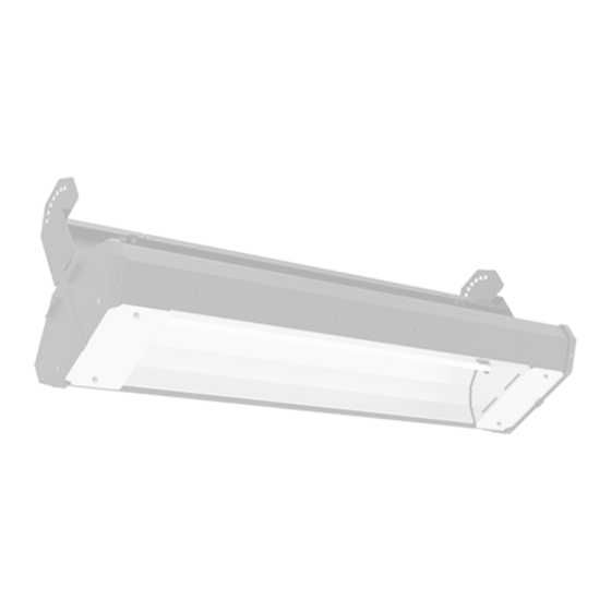
INSTALLATION AND SERVICE MANUAL
Overhead Electric Infrared Heaters
!
!
INSTRUCTIONS APPLY TO:
Installation
Operation
HAZARD INTENSITY LEVELS
• DANGER: Failure to comply will result in severe
personal injury or death and property damage
• WARNING: Failure to comply could result in severe
personal injury or death and/or property damage.
• CAUTION: Failure to comply could result in minor
personal injury and/or property damage.
CONTENTS
Section
1. Safety ....................................................................3
2. Installation ........................................................... 11
3. Maintenance ....................................................... 18
4. Parts List .............................................................20
5. Limited Warranty .................................................23
These heaters must NOT be used in the
following applications:
• Enclosed swimming pool areas
• Areas with contaminated atmospheres.
• Areas requiring explosion-proof equipment.
• Process heating applications.
ATTENTION
Mount a copy of these instructions adjacent to
the heater and retain a copy for future reference.
2-528
August 2023
Models MEL
Maintenance
Page
Advertisement
Table of Contents

Related Manuals for Modine Manufacturing MELMEL-24B1-120 Series


Summary of Contents for Modine Manufacturing MELMEL-24B1-120 Series
- Page 1 2-528 August 2023 INSTALLATION AND SERVICE MANUAL Overhead Electric Infrared Heaters Models MEL INSTRUCTIONS APPLY TO: Installation Operation Maintenance WARNING HAZARD INTENSITY LEVELS Improper installation, adjustment, alteration, service or • DANGER: Failure to comply will result in severe maintenance can cause property damage, injury or personal injury or death and property damage death.
-
Page 2: Table Of Contents
Series Contents 1.0 Safety ................3 Safety Symbols . -
Page 3: Safety
Safety • Safety Symbols • Applications Series Safety WARNING Improper installation, adjustment, alteration, service, or maintenance can cause property damage, serious injury, or death . Read and understand the installation, operating, and maintenance instructions thoroughly before installing or servicing this equipment . Only trained, qualified personnel with proper electrical experience may install or service this equipment . -
Page 4: Model Number Designation Chart
Safety • Model Number Designation Chart • Available Models Series Chart 1.1 • Model Number Designation Chart Series Material Type Lamp Quantity Voltage MEL-24 MEL-33 B = Black Powder Coat with Black Nylon End Caps MEL-46 Model Configuration Examples: MEL-24B1-120 Chart 1.2 •... - Page 5 Series Safety • Available Models Chart 1.3 • Available Models and Specifications - 33” Series Lamp Type Voltage* Total Amps Total Watts BTU/h MEL-33B1-208 H .O . Medium Wave 208 V 10 .20 2,125 7,251 MEL-33B1-240 H .O . Medium Wave 240 V 8 .85 2,125...
- Page 6 Safety • Available Models Series Chart 1.4 • Available Models and Specifications - 46” Series Lamp Type Voltage* Total Amps Total Watts BTU/h MEL-46B1-277 H .O . Medium Wave 277 V 11 .55 3,200 10,919 MEL-46B1-480 H .O . Medium Wave 480 V 6 .66 3,200...
-
Page 7: Clearances To Combustibles
Series Safety • Clearances to Combustibles Clearances to Combustibles WARNING Placement of explosive objects, flammable objects, liquids, and vapors close to the heater may result in explosion, fire, property damage, serious injury, or death . Do not store or use explosive objects, liquids, or vapors in the vicinity of the heater . - Page 8 Safety • Clearances to Combustibles Series Chart 1.5 • Clearances to Combustibles in Inches (Millimeters) - see Figure 1.1 Min. Mtg. Side Mounting Height Length Angle Front Behind Below Canada Single Element 24’’ 0° 16 (407) 16 (407) 12 (305) 6 (153) 56 (1423) 33’’...
-
Page 9: Safety Labels And Their Locations
Safety • Safety Labels and Their Locations Series Safety Labels and Their Locations It is important to provide warnings to alert individuals to potential hazards and safety actions . Signs should state the hazards for the particular application and be legible to the building occupants . Consult the factory or a factory representative for additional information on signage compliance . -
Page 10: Standards, Certifications, And Government Regulations
Safety • Standards, Certifications, and Government Regulations Series Standards, Certifications, and Government Regulations Installation of this infrared heater must comply with all applicable local, state, and national specifications, regulations, and building codes . Contact the local building inspector and/or fire marshal for guidance . The heater must be electrically grounded in accordance with the following codes: United States: Refer to National Electrical Code ®... -
Page 11: Installation
Installation • Design Series Installation WARNING Read and understand the installation, operation, and maintenance instructions thoroughly before installing or servicing this equipment . Design To ensure a safe, properly designed heating system, a layout should be developed for the correct placement of the infrared heater(s) . - Page 12 Installation • Design Series Chart 2.1 • Estimating Required Heat Load Watts Required per Square Type of Building Foot at Floor Level* Insulated 5 to 10 Uninsulated 10 to 15 Outdoor Sheltered 20 to 30 Outdoor Unsheltered 25 to 40 * For load purposes only, not for determining coverage .
-
Page 13: Heater Mounting
Installation • Heater Mounting Series Heater Mounting WARNING Improper suspension of the infrared heater may result in collapse and being crushed . Always suspend from a permanent part of the building structure that can support the total force and weight of the heater . Failure to maintain minimum clearance to combustibles may result in fire and/or explosion, property damage, serious injury, or death . - Page 14 Installation • Top Channel Assembly Series Top Channel Assembly Attach the mounting brackets to the top wire raceway . On each end, place (1) 1/4” x 1/2” bolt through the bottom hole of the mounting bracket and through the bottom hole of the top wire raceway . Place (1) 1/4” lock nut on each bolt .
-
Page 15: Lamp Installation
Installation • Lamp Installation Series Lamp Installation CAUTION Disconnect power prior to installing or replacing supplied quartz lamp(s) . The elements can and should be installed prior to mounting the heater . Ensure appliance is OFF and is cool to the touch . Remove both service access panels using a 1/4”... -
Page 16: Outdoor Application
Installation • Outdoor Applications • Electrical Series Outdoor Applications CAUTION For totally exposed outdoor applications (not ceiling protected) ensure connections are made as illustrated in Figure 2 .6 . Figure 2.6 • Outdoor Application 6” Minimum NOTE: All conduit, conduit fittings, and junction boxes are field supplied . Must be NEMA Type 4X or equivalent . - Page 17 Series Installation • Wiring Diagrams Wiring Diagrams Figure 2.7 • Wiring Diagram for Units with 1 Lamp LAMP NO. 1 Figure 2.8 • Wiring Diagram for Units with 2 Lamps LAMP NO. 1 LAMP NO. 2 Figure 2.9 • Wiring Diagram for Units with 3 Lamps LAMP NO.
-
Page 18: Maintenance
Maintenance • Maintenance Log Series Maintenance The following should become a standard yearly procedure to obtain maximum operating efficiency and trouble-free operation . During long periods of non-usage, remove or cover heater with a polyethylene bag and disconnect from power supply . -
Page 19: Troubleshooting Guide
Series Maintenance • Troubleshooting Guide Troubleshooting Guide Process Start Corrective Question Question Action Turn Heater on from power source. Does the heating Are the heating lamps Replace heating lamp(s) . physically damaged? lamp(s) turn on? Are the heating lamps Rewire lamps as indicated wired as indicated in in this manual . -
Page 20: Heater Assembly Components
Maintenance • Heater Assembly Components Series Heater Assembly Components For complete information on MEL series replacement parts, contact your installation contractor . Figure 3.1 • Components 80128 80129 80130 80136 80131 80137 80138 80132 80132 80133 80134 80147 80157 80144, 80145, 80146 80148 80167 80134... -
Page 21: Parts List
Series Maintenance • Parts List Parts List Chart 3.1 • General Parts Part No. Description Part No. Description 80128 Mounting Brackets (set of 2) Double Element Model-Specific Parts 80129 12 Gauge Wire Length for 33” (specify color) 80149 Chassis Assembly with Lamp Stopper 80130 12 Gauge Wire Length for 24”... - Page 22 Maintenance • Parts List Series Chart 3.2 • Elements Part No. Description 80116 120 V, 1360 W, 24” Long 80117 208 V, 1360 W, 24” Long 80118 240 V, 1360 W, 24” Long 80119 277 V, 1360 W, 24” Long 80120 480 V, 1360 W, 24”...
- Page 23 Heating and Indoor Air Quality Products This Warranty (the “Warranty”) shall apply to Products (as EXCLUSIONS AND LIMITATIONS: This Warranty is subject to defined below) sold by Modine Manufacturing Company, a the following exclusions and limitations: Wisconsin corporation (“Seller”) to you (“Buyer”).
- Page 24 2 YEARS 30 MONTHS Condensers, Burners, Sheet Metal As Modine Manufacturing Company has a continuous product improvement program, it reserves the right to change design and specifications without notice. Modine Manufacturing Company 1500 DeKoven Avenue Racine, WI 53403 Phone: 1.800.828.4328 (HEAT) www.modinehvac.com...
Need help?
Do you have a question about the MELMEL-24B1-120 Series and is the answer not in the manual?
Questions and answers