Table of Contents
Advertisement
Quick Links
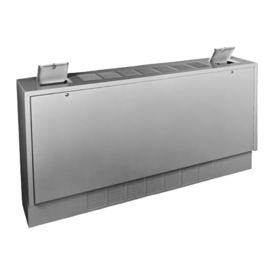
Floor Model FC
Sizes 002 thru 014
Contents
General Information ...............................................................1
Special Precautions ...............................................................2
SI (Metric) Conversion Factors ..............................................2
Unit Location..........................................................................2
Installation..............................................................................3
Unit Mounting ..................................................................3
Piping ..............................................................................3
Wiring ..............................................................................3
Mounting Height and Heater Throw ................................4
Operation ...............................................................................4
Prior to Operation ..............................................................4
Initial Start-up .....................................................................4
Automatic Control Operations ............................................4
Air Flow Arrangement ............................................................5
Controls and Features ...........................................................6
Specifications .....................................................................7,8
Dimensional/Motor Data ........................................................8
Floor Model FC ...............................................................9
Wall or Ceiling Model WCC ..........................................10
Dimensional Data/Accessories/Options ........................ 11
Outside Air Wall Box ..................................................... 11
Duct Collars .................................................................. 11
Maintenance ........................................................................12
Service.................................................................................12
Wiring Diagram ....................................................................13
Warranty ................................................................ Back Page
IMPORTANT
The use of this manual is specifically intended
for a qualified installation and service agency.
A qualified installation and service agency must
perform all installation and service of these
appliances.
PLEASE BE SURE TO LEAVE IT WITH THE OWNER WHEN YOU LEAVE THE JOB.
INSTALLATION AND SERVICE MANUAL
steam/hot water cabinet unit heaters
Wall or Ceiling Model WCC
Sizes 002 thru 014
Inspection on Arrival
1. Inspect unit upon arrival. In case of damage, report
2. Check rating plate on unit to verify that power supply meets
3. Inspect unit received for conformance with description of
General Information
Installation and service instructions in this manual are applicable
to the three types of steam/hot water cabinet unit heaters which
should be installed in their proper applications for their most
effective function as heating units.
The 1 & 2 row condensers are warranted for operation at
hot water pressures up to 200 lbs. per sq. in. gauge, and or
temperatures up to 240°F or steam pressures up to 10psig for
one row coils only.
The 3 & 4 row condensers are warranted for operation at
hot water pressures up to 200 lbs. per sq. in. gauge, and or
temperatures up to 200°F.
Motors are designed for continuous duty. They can operate in a
maximum ambient temperature of 104°F (40°C).
The unit heaters are listed by the Canadian Standards
Association as certified.
Model FC units are fully exposed floor mounted types.
Model WCC units are fully exposed wall or ceiling mounted
types, or partially of fully recessed.
Cabinet unit heaters are available with a variety of options
and control arrangements. Information on certain options
and controls (when provided) is supplied separately from this
manual.
THIS MANUAL IS THE PROPERTY OF THE OWNER.
Wall or Ceiling Recessed
Model WCC
Sizes 002 thru 014
immediately to transportation company and your local
Modine Sales Representative.
available electric power at point of installation.
product ordered (including specifications where applicable).
AIR11-500.8
5H0796080000
February, 2020
Advertisement
Table of Contents

Related Manuals for Modine Manufacturing AIR11-500.8


Summary of Contents for Modine Manufacturing AIR11-500.8
-
Page 1: Table Of Contents
AIR11-500.8 5H0796080000 February, 2020 INSTALLATION AND SERVICE MANUAL steam/hot water cabinet unit heaters Wall or Ceiling Recessed Floor Model FC Wall or Ceiling Model WCC Model WCC Sizes 002 thru 014 Sizes 002 thru 014 Sizes 002 thru 014 Inspection on Arrival Contents General Information ...............1... -
Page 2: Special Precautions
6. Arrange horizontal delivery units so they do not blow replacement parts list may be obtained by contacting directly at occupants. Modine Manufacturing Company. Refer to the rating plate 7. When only vertical delivery units are installed, they should on the appliance for complete appliance model number, be located so exposed walls are blanketed by their air serial number, and company address. -
Page 3: Installation
Remove the screwdriver. Pull on the wire to make sure that 4. Install piping to provide for expansion and contraction it is securely clamped in the terminal. normally encountered with temperature changes. Make sure that the terminal clamp is in contact with bare wire (insulation removed). AIR11-500.8... -
Page 4: Operation
“T” of cabinet unit heaters when operated with steam pressures other than 2 pounds or with water at other than entering temperature of 220°F. Steam Pressure 150° 160° 170° 180° 190° 200° 210° 220° 230° 240° AVERAGE WATER TEMP. (°F) AIR11-500.8... - Page 5 5 - 100% OA Motorized Damper 0 - Wall or Floor 0 - None D - Duct Collar 6 - 25% OA Motorized Damper 5 - Ceiling 1 - Spanner Head A - Adjustable Louvers 9 - Inverted 2 - Key Locks AIR11-500.8...
-
Page 6: Controls And Features
For units with the EC motor option, a 3 speed switch with off position for motor control only will be provided. AIR11-500.8... - Page 7 * Standard solid state speed control offers infinite speed control between high and low speed/CFM on standard PSC motor. * Three speed switch offers high, medium & low speed/CFM on standard EC motor Sizes 002-006 have one motor. Sizes 008-014 have two motors. AIR11-500.8...
- Page 8 MECHANICAL SPECIFICATIONS / UNIT Table 8.1 3 & 4 Row Unit Data Specifications Unit Size Coil High Capacity – 3 Row Face Area, Ft.2 High Capacity – 4 Row Face Area, Ft.2 7/8" I.D 7/8" I.D 7/8" I.D 7/8" I.D 1-1/8"...
-
Page 9: Dimensional/Motor Data
DIMENSIONAL / MOTOR DATA FLOOR MOUNTED Figure 9.1 - Floor Model FC, Sizes 002-014 Steam/Hot Water Cabinet Unit Heaters ACCESS ACCESS DOOR DOOR " COIL CONNECTIONS SIZES 002-006: " I.D. SWEAT STANDARD COIL " " I.D. SWEAT FOR TWO ROW COIL SIZES 008-014: 1- "... - Page 10 DIMENSIONAL / MOTOR DATA EXPOSED OR RECESSED WALL/CEILING MOUNTED Figure 10.1 - Wall or Ceiling Model WCC, Sizes 002-014 Steam/Hot Water Cabinet Unit Heaters ➀ COIL CONNECTIONS SIZES 002-006: " I.D. SWEAT STANDARD COIL " I.D. SWEAT FOR TWO ROW COIL SIZES 008-014: 1- "...
- Page 11 COIL CONNECTION DIMENSIONS (3 & 4 ROW COIL UNITS): Table 11.1 11-500.8...
-
Page 12: Dimensional Data/Accessories/Options
DIMENSIONAL DATA - ACCESSORIES / OPTIONS Figure 12.1 Table 12.1 ➀ ➁ Model WCC - Duct Collars Model WCC 100% Air Inlet or Outlet Duct Collars Unit Size 3/4" 18-1/4 4-1/4 10-3/8 2-1/2 23-1/4 4-1/4 10-3/8 2-1/2 28-1/4 4-1/4 10-3/8 2-1/2 41-1/4 4-1/4... -
Page 13: Maintenance
MAINTENANCE / SERVICE B. Internal Corrosion Safeguards All heating equipment should be serviced before each heating season to assure proper operations. The following items may 1. Provide controlled water treatment — don’t use excess of be required to have more frequent service scheduled based on boiler compounds. - Page 14 THIS PAGE INTENTIONALLY LEFT BLANK 11-500.8...
- Page 15 THIS PAGE INTENTIONALLY LEFT BLANK 11-500.8...
-
Page 16: Warranty
Burners High Intensity Infrared Units Sheet Metal Parts All Products As Modine Manufacturing Company has a continuous product improvement program, it reserves the right to change design and specifications without notice. Modine Manufacturing Company 1500 DeKoven Avenue Racine, Wisconsin 53403-2552 Tel: 1.800.828.4328 (HEAT)
Need help?
Do you have a question about the AIR11-500.8 and is the answer not in the manual?
Questions and answers