Table of Contents
Advertisement
W ARNING
1. Improper installation, adjustment, alteration,
service, or maintenance can cause property
damage, injury, or death, and could cause
exposure to substances which have been
determined by various state agencies to
cause cancer, birth defects, or other
reproductive harm. Read the installation,
operating, and maintenance instructions
thoroughly before installing or servicing
this equipment.
2. Do not locate ANY gas-fired units in areas
where chlorinated, halogenated, or acidic
vapors are present in the atmosphere.
These substances can cause premature
heat exchanger failure due to corrosion,
which can cause property damage, serious
injury, or death.
FOR YOUR SAFETY
WHAT TO DO IF YOU SMELL GAS:
1. Open windows.
2. Do not try to light any appliance.
3. Do not touch any electrical switch; do not
use any phone in your building.
4. Extinguish any open flame.
5. Immediately call your gas supplier from
a neighbor's phone. Follow the gas
supplier's instructions. If you can not
reach your gas supplier, call your fire
department.
PLEASE BE SURE TO LEAVE IT WITH THE OWNER WHEN YOU LEAVE THE JOB.
INSTALLATION AND SERVICE MANUAL
Inspection on Arrival
1. Inspect unit upon arrival. In case of damage, report it
2. Check rating plate on unit to verify that power supply meets
3. Inspect unit upon arrival for conformance with description of
Table of Contents
Inspection on Arrival . . . . . . . . . . . . . . . . . . . . . . . . . . . . . . . . . 1
Special Precautions . . . . . . . . . . . . . . . . . . . . . . . . . . . . . . . . . 2
SI (Metric) Conversion Factors . . . . . . . . . . . . . . . . . . . . . . . . 3
Before You Begin . . . . . . . . . . . . . . . . . . . . . . . . . . . . . . . . . . . 3
Unit Location . . . . . . . . . . . . . . . . . . . . . . . . . . . . . . . . . . . . . . 4
Installation . . . . . . . . . . . . . . . . . . . . . . . . . . . . . . . . . . . . . . . . 6
Start-Up Procedure/Operation . . . . . . . . . . . . . . . . . . . . . . . . 24
Unit Components . . . . . . . . . . . . . . . . . . . . . . . . . . . . . . . . . . 25
Performance Data - General . . . . . . . . . . . . . . . . . . . . . . . . . 26
Performance Data - Downturn Hoods . . . . . . . . . . . . . . . . . . 27
Dimensions. . . . . . . . . . . . . . . . . . . . . . . . . . . . . . . . . . . . . . . 28
Service/Troubleshooting. . . . . . . . . . . . . . . . . . . . . . . . . . . . . 30
Model/Serial Number/Replacement Parts . . . . . . . . . . . . . . . 31
Commercial Warranty. . . . . . . . . . . . . . . . . . . . . . . . Back Cover
THIS MANUAL IS THE PROPERTY OF THE OWNER.
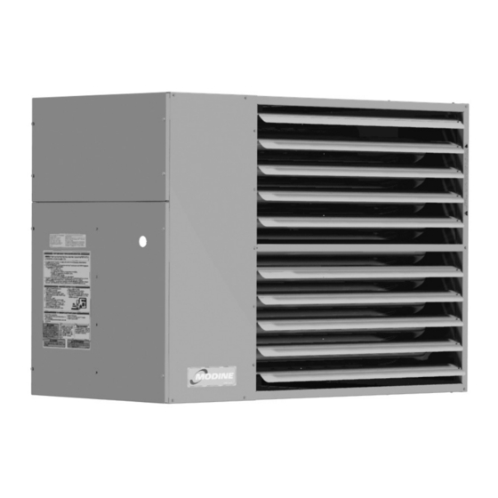
gas-fired unit heaters
model PTX and BTX
All models approved for use in California by the CEC and in
Massachusetts. Unit heater is certified for non-residential
applications.
FOR YOUR SAFETY
The use and storage of gasoline or other
flammable vapors and liquids in open containers
in the vicinity of this appliance is hazardous.
IMPOR T ANT
The use of this manual is specifically intended
for a qualified installation and service agency.
All installation and service of these units
must be performed by a qualified installation
and service agency.
immediately to transportation company and your local
Modine sales representative.
available electric power at the point of installation.
product ordered (including specifications where applicable).
Combustible Material and Service Clearances . . . . . . . . . . 4
Unit Mounting . . . . . . . . . . . . . . . . . . . . . . . . . . . . . . . . . . . . 5
Venting . . . . . . . . . . . . . . . . . . . . . . . . . . . . . . . . . . . . . . . . . 6
Gas Connections . . . . . . . . . . . . . . . . . . . . . . . . . . . . . . . . 15
High-Altitude Accessory Kit . . . . . . . . . . . . . . . . . . . . . . . . 16
Electrical . . . . . . . . . . . . . . . . . . . . . . . . . . . . . . . . . . . . . . 18
Installation with Ductwork. . . . . . . . . . . . . . . . . . . . . . . . . . 19
6-534.1
5H0907880000
March, 2023
Advertisement
Table of Contents

Related Manuals for Modine Manufacturing PTX


Summary of Contents for Modine Manufacturing PTX
-
Page 1: Table Of Contents
6-534.1 5H0907880000 March, 2023 INSTALLATION AND SERVICE MANUAL gas-fired unit heaters model PTX and BTX All models approved for use in California by the CEC and in Massachusetts. Unit heater is certified for non-residential applications. FOR YOUR SAFETY The use and storage of gasoline or other flammable vapors and liquids in open containers in the vicinity of this appliance is hazardous. -
Page 2: Special Precautions
SPECIAL PRECAUTIONS W ARNING SPECIAL PRECAUTIONS 12. When servicing or repairing this equipment, use only THE INSTALLATION AND MAINTENANCE INSTRUCTIONS IN factory-approved service replacement parts. A complete THIS MANUAL MUST BE FOLLOWED TO PROVIDE SAFE, replacements parts list may be obtained by contacting EFFICIENT AND TROUBLE-FREE OPERATION. -
Page 3: Si (Metric) Conversion Factors
SPECIAL PRECAUTIONS / SI (METRIC) CONVERSION FACTORS BEFORE YOU BEGIN CAUTION CAUTION 16. Purging of air from gas supply line should be performed as described in the National Fuel Gas Code, ANSI Z223.1 1. All literature shipped with this unit should be kept for future (NFPA 54) - latest edition. -
Page 4: Unit Location
UNIT LOCATION Figure 4.1 - Combustible Material and Service Clearances DANGER Appliances must not be installed where they may be exposed to a potentially explosive or flammable atmosphere. CAUTION ACCESS 1. Clearances to combustible materials are critical. Be sure to ACCESS SIDE follow all listed requirements. -
Page 5: Unit Mounting
UNIT MOUNTING Figure 5.1 - Unit Heater Suspension Methods CAUTION 1. Do not install units below 7' measured from the bottom of the unit to the floor in commercial applications (unless unit is properly guarded to provide user protection from moving parts). -
Page 6: Installation
CSA B149.1. Clearance from the vent pipe (or the top of the unit) may be Model PTX/BTX unit heaters must be vented with the proper required to be greater than 6" if heat damage other than fire could result (such as material distortion or discoloration). - Page 7 INSTALLATION - VENTING A9. When the vent passes through a combustible INTERIOR A12. Vent termination clearances as shown in Table 7.1: wall or floor, a metal thimble 4" greater than the vent A13. Do NOT vent this appliance into a masonry chimney. diameter is necessary.
- Page 8 INSTALLATION - VENTING Vertical Vent Only - Category I Vent Determination A22. This unit may be installed with or without the combustion (Not Separated Combustion) air intake pipe. Using the vent pipe only allows for greater maximum vent length but is not considered "separated •...
- Page 9 INSTALLATION - VENTING Section B – Vertical Vent Only, Category I Vent Table 9.1 - Minimum Height from Roof to Lowest System Venting Instructions Discharge Opening B1. This section applies to vertically vented Category I Rise X (in) Roof Pitch Min Height H (ft) j vent systems and is in addition to "Section A - General Flat to 6/12...
- Page 10 INSTALLATION - VENTING Section C – Horizontal Vent Only, Category III Vent Figure 10.1 - Vent Construction Through Combustible Walls and Support Bracket System Venting Instructions C1. This section applies to horizontally vented Category III METAL FIBER GLASS vent systems and is in addition to "Section A – General SLEEVE INSULATION MIN.
- Page 11 INSTALLATION - VENTING Section D - Vertical Combustion Air and Vent - Figure 11.1 - Vertical 2-Pipe Vent System Category III Vent (Separated Combustion) Venting Instructions LISTED TERMINAL D1. This section applies to vertically vented 2-pipe (1 combustion air inlet pipe and 1 vent pipe) vent systems "H"...
- Page 12 INSTALLATION - VENTING Section E - Horizontal Combustion Air and Vent - E9. When condensation may be a problem, the vent system shall not terminate over public walkways or over an area Category III Vent System Determination where condensate or vapor could create a nuisance or (Separated Combustion) Venting Instructions hazard, or could be detrimental to the operation of E1.
- Page 13 INSTALLATION - VENTING CAUTION F3. Once the kit contents have been verified as correct for the direction of venting, the concentric vent adapter box is to installed. Determine the location of the box. Be sure to maintain all clearances as listed in these instructions. The concentric vent adapter box must be installed inside of the structure or building.
- Page 14 INSTALLATION - VENTING Table 14.1 - Concentric Vent Pipe Sizes F9. Slide the combustion air pipe over the vent pipe and attach to the air inlet of the concentric adapter box, as Single Wall Pipe shown in Figure 14.1, using at least 3 corrosion-resistant Type B Vent Pipe ...
-
Page 15: Gas Connections
INSTALLATION - GAS CONNECTIONS GAS CONNECTIONS Figure 15.1 - Recommended Sediment Trap/Manual Shut-off Valve Installation - Side or Bottom Gas W ARNING Connection 1. All field gas piping must be pressure/leak tested prior to operation. Never use an open flame. Use a soap solution or equivalent for testing. -
Page 16: High-Altitude Accessory Kit
INSTALLATION - HIGH ALTITUDE ACCESSORY KIT Manifold Pressure Adjustment HIGH ALTITUDE ACCESSORY KIT The inlet pressure to the unit must be confirmed to be within Modine’s gas-fired equipment standard input ratings are acceptable limits (6-7" W.C. for natural gas and 11-14" W.C. certified by ETL. - Page 17 INSTALLATION - HIGH ALTITUDE ACCESSORY KIT If the heating value of the gas being supplied is different than the values Table 17.1 - High Altitude Kits for PTX/BTX ➀ shown in Tables 16.1 and 16.2, use the following equation to determine the...
-
Page 18: Electrical
INSTALLATION - ELECTRICAL CONNECTIONS ELECTRICAL CONNECTIONS Figure 18.1 - Contractor Convenience Box with Toggle Switch W ARNING 1. Disconnect power supply before making wiring SUPPLY CONDUIT UNIT ON/OFF connections to prevent electrical shock and equipment POWER ENTRY SWITCH KNOCKOUTS TERMINAL BOARD damage. -
Page 19: Installation With Ductwork
INSTALLATION WITH DUCTWORK Figure 19.1- Typical Duct & Airflow Installation Recommended Installations Dimension “B” Should Never Be Less than 1/2 of “A” 3" MAX. TURNING 12" VANES 12" MIN. 3" MIN. MIN. 3" MIN. 12" TURNING VANES 3" MAX. BAFFLE TURNING VANES 12"... -
Page 20: Requirements/Adjustments And Data For Blower Units
INSTALLATION To Install Blower Adjustments 1. Remove and discard the motor tie down strap and the Following electrical connections, check blower rotation to assure shipping block beneath the motor adjustment screw (not used blow-through heating. If necessary interchange wiring to reverse on all models.) blower rotation. - Page 21 BLOWER PERFORMANCE DATA - MODEL BTX Table 21.1 - Power Code Description - Blower Model BTX - BTX150 BTX175 BTX200 BTX250 BTX300 BTX350 BTX400 Power Voltage Phase Code Drive Drive Drive Drive Drive Drive Drive 115/230 1 1/2 1 1/2 208-230/460 1 1/2 1 1/2...
- Page 22 BLOWER PERFORMANCE DATA - MODEL BTX Table 22.1 - Blower Model BTX 150-250 (40-55°F temp rise for 250 size unit) - ‚ ƒ External Static Pressure ("W.C.) Model Size RPM Drive Turns RPM Drive Turns RPM Drive Turns RPM Drive Turns RPM Drive Turns RPM Drive Turns RPM Drive Turns...
- Page 23 BLOWER PERFORMANCE DATA - MODEL BTX Table 23.1 - Blower Model BTX 250-400 (60-70°F temp rise for 250 size unit) - ‚ƒ External Static Pressure ("W.C.) Model Size Drive Turns Drive Turns RPM Drive Turns RPM Drive Turns RPM Drive Turns Drive Turns...
-
Page 24: Start-Up Procedure/Operation
INSTALLATION - OPERATION OPERATION 10. Turn on power to the unit at the disconnect switch. 11. Check the thermostat, ignition control, gas valve, and supply Prior to Operation fan blower motor for electrical operation. If these do not function, recheck the wiring diagram. IMPOR T ANT 12. -
Page 25: Unit Components
CONTROL OPERATING SEQUENCE / UNIT COMPONENTS CONTROL OPERATING SEQUENCE Upon a call for heat from the thermostat, power is supplied to not already started it will start shortly. If a flame is not sensed the power exhauster motor. The unit will go through a purge within 7 seconds for any reason the main valve will close and period and then the direct spark igniter will be energized. -
Page 26: Performance Data - General
GENERAL PERFORMANCE DATA - MODELS PTX & BTX Table 26.1 - Propeller Unit Model PTX General Performance Data Model PTX Sizes Btu/Hr Input 150,000 175,000 200,000 250,000 300,000 350,000 400,000 123,000 143,500 166,000 207,500 249,000 290,500 332,000 Btu/Hr Ouput ... -
Page 27: Performance Data - Downturn Hoods
90° HOOD Figure 27.2 - 30° and 60° Throw/Floor Coverage 30 DOWNTURN 60 DOWNTURN MOUNTING HEIGHT Table 27.2 - Deflector Hood General Performance 60 DOWNTURN Data - Model PTX 30 DOWNTURN 30° Hood 60° Hood 90° Hood Note: Temp Mounting... -
Page 28: Dimensions
DIMENSIONAL DATA - MODEL PTX Propeller Units - Model PTX Figure 28.1 - Dimensional Drawings Table 28.1 - Dimensions (inches) - PTX Models PTX150 PTX175 PTX200 PTX250 PTX300 PTX350 PTX400 35.53 42.53 42.53 42.53 42.53 42.53 42.53 23.06 25.81 25.81... - Page 29 DIMENSIONAL DATA - MODEL BTX Blower Units - Model BTX Figure 29.1 - Dimensional Drawings BLOWER ENCLOSURE 6 MOUNTING (OPTIONAL) 4 7/8" HOLES FILTER RACK 7/8" (OPTIONAL) 4.88 ADJUSTABLE LOUVERS O x P OPENING M (APPROX.) Q (MIN DIST TO WALL) Table 29.1 - Dimensions (inches) - BTX Models BTX150 BTX175 BTX200 BTX250 BTX300 BTX350 BTX400...
-
Page 30: Service/Troubleshooting
SERVICE / MAINTENANCE / TROUBLESHOOTING W ARNING 1. Service air moving components annually. a. Check fan for fit on motor shaft and for damage to blades. 2. Keep unit free from dust, dirt, grease, and foreign matter, When servicing or repairing this equipment, use only paying particular attention to: factory-approved service replacement parts. -
Page 31: Model/Serial Number/Replacement Parts
PTX 200 Factory Installed Option Digit Gas-Fired Unit Heaters N - None Unit Configuration C - BMS - (Building Management Systems) PTX - Propeller Unit, 150-400MBH BTX - Blower Unit, 150-400MBH Future A - All MBH Input (refer to page 22) -
Page 32: Commercial Warranty
Burners High Intensity Infrared Units Sheet Metal Parts All Products As Modine Manufacturing Company has a continuous product improvement program, it reserves the right to change design and specifications without notice. Modine Manufacturing Company 1500 DeKoven Avenue Racine, WI 53403 Phone: 1.800.828.4328 (HEAT)
Need help?
Do you have a question about the PTX and is the answer not in the manual?
Questions and answers