Table of Contents
Advertisement
Quick Links
Advertisement
Table of Contents

Subscribe to Our Youtube Channel
Related Manuals for Tysso POS-1000B-P


Summary of Contents for Tysso POS-1000B-P
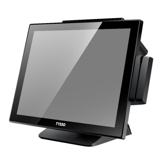
- Page 1 POS-1000B-P Fanless Full-Flat POS Terminal User Manual Installation Guide Copyright © 2021 Fametech Inc. All Rights Reserved. All other brands, product names, company names, trade names, trademarks and service marks used herein are the property of their respective owners.
-
Page 2: Table Of Contents
Contents General Information Revision History About This Manual Disclaimer Warning Caution Warranty Limits Trade Marks and Service Marks Important Safety Information Product Overview Packing Specifications Dimension Part Description I/O Ports POS Installation Unpack Your POS Install Your POS Appendix Replace Hard Disk Install the Modular Customer Display (Optional) Install the MSR &... -
Page 3: General Information
General Information Revision History Date Version Update Summary Remark Approved By 1. Change product picture to drawing (cover). 2021/06/29 V3.1 Harrel Chen Jamie Chang 2. Change figure “Quick Installation Guide” (p.7) Copyright © 2021 Fametech Inc. All Rights Reserved. All other brands, product names, company names, trade names, trademarks and service marks used herein are the property of their respective owners. -
Page 4: About This Manual
About This Manual The purpose of this user’s manual is to provide general information on TYSSO’s POS Terminal and to show the users how to configure the hardware-related configurations. The information in this manual is subject to change without notice due to rapid improvement on IT technology. -
Page 5: Caution
Warranty does not cover any damage caused by improper use. Trade Marks and Service Marks TYSSO is a registered trademark of FAMETECH INC. Other brand and product names are trademarks and registered trademarks and service marks of their respective owners. -
Page 6: Important Safety Information
Important Safety Information Read following instructions carefully. Use only parts, especially power adapter, recommended by the manufacturer; unapproved parts may be hazardous. Before plugging the power cord into the AC inlet of the power supply unit, make sure that the voltage applied to the power outlet is within the specified range (100V~240V). -
Page 7: Product Overview
Product Overview Packing POS Unit Power Adapter AC Power Cord Quick Installation Guide Contents POS Unit Power Adapter AC Power Cord Quick Installation Guide Optional Accessories* Magnetic Stripe Card Reader (MSR) i-Button Module ... -
Page 8: Specifications
Specifications Model Name POS-1000B-P Main Board Intel® Bay Trail-D Platform, Celeron® Processor J1900 (2.0 GHz, 2M Cache) System Memory 2 x DDR3L SO-DIMM 1333MHz, up to 8 GB Graphic Intel® HD Graphics OS Support POSReady7, Windows7, Windows8.1, Windows10, Linux Display 15”... -
Page 9: Optional Accessories
Optional Accessories Optional Accessories 8" (800x 600), 10.4"(800x600) and 15" (1024x768) LCD Display selectable 2nd Display Optional Touchscreen Customer Display VFD, 20 Columns x 2 Lines Magnetic Stripe Reader Bi-directional, comply with ISO 7811 and Track 1 & 2 & 3 supported (MSR) (HID USB) i-Button... -
Page 10: Dimension
Dimension Left View Front View Right View Rear View Bottom View Note: The Magnetic Stripe Card Reader (MSR) and i-Button Module are optional parts and may not be included in the package. Please purchase the optional parts separately. Copyright © 2021 Fametech Inc. All Rights Reserved. All other brands, product names, company names, trade names, trademarks and service marks used herein are the property of their respective owners. -
Page 11: Part Description
Part Description Front View LCD Touch Screen i-Button Module (Optional) MSR Module (Optional) Power Indicator Base Rear View Customer Display (Optional) i-Button Module MSR Module (Optional) (Optional) Power Switch Base Cable Outlet Copyright © 2021 Fametech Inc. All Rights Reserved. All other brands, product names, company names, trade names, trademarks and service marks used herein are the property of their respective owners. -
Page 12: Side View
Side View Customer Display (Optional) i-Button Module (Optional) Side I/O Port (USB) Power Switch Power Switch Left View (with Optional Customer Display) Left View Customer Display (Optional) Side I/O Port (USB) Side I/O Port (RS-232) MSR Module (Optional) Right View (with Optional MSR) Right View Note: The right I/O ports (USB, RS-232) are reserved for MSR Module. - Page 13 Bottom View (Base) Cable Slot Bottom View (POS Unit) HDD Slot Bottom I/O Ports Copyright © 2021 Fametech Inc. All Rights Reserved. All other brands, product names, company names, trade names, trademarks and service marks used herein are the property of their respective owners.
-
Page 14: I/O Ports
I/O Ports Main Power Input 12V DC Parallel Port (Optional) USB Ports COM3 Modular HDD Slot RJ-45 COM1 COM2 RJ11 (LAN) (Cash Drawer) Bottom I/O Ports Side I/O Port (USB) Side I/O Ports Copyright © 2021 Fametech Inc. All Rights Reserved. All other brands, product names, company names, trade names, trademarks and service marks used herein are the property of their respective owners. - Page 15 I/O Ports Descriptions: I/O Port Description Connect devices with USB connectors 4-pin rounded-power-jack for connecting an AC to +12VDC 12V IN power adapter. There are DB9 type and USB Type A with RI/+5VDC/+12VDC output by BIOS COM1, COM2, COM3: DB9 type with RI/+5V /12V by BIOS setting in I/O Bracket COM4: USB Type A (with RI/+5V /12V by BIOS setting in Panel Side COM5:...
-
Page 16: Pos Installation
POS Installation Unpack Your POS The contents may vary with different options. If there’s any physical damage or missing parts, please contact your supplier immediately. Please keep all packing materials in case you need to ship back the device for service. ... -
Page 17: Install Your Pos
Install Your POS Power Adapter POS Terminal Power Cord Electrical Outlet Place the POS terminal on the proper location. Pass the power connector of the power adapter through the Base Cable Slot. Connect the power connector to the POS unit (Main Power Base Cable Slot Input). -
Page 18: Appendix
Appendix Replace Hard Disk HDD Module (HDD inside) a. Remove the securing screw of the HDD Module from the POS unit, and pull out the HDD Module to detach it from POS terminal. Securing Screw b. Loosen the securing screws, and remove the hard disk from the bracket. -
Page 19: Install The Modular Customer Display (Optional)
Install the Modular Customer Display (Optional) Securing Screws x 2 a. Connect the connector of the Modular Customer Display to the POS Unit, and tighten the Modular Customer securing screws of the Modular Display Customer Display. Connector Note: ... -
Page 20: Install The Msr & I-Button Module (Optional)
Install the MSR & i-Button Module (Optional) a. Switch the POS Unit Off. b. Install the i-Button Module to the I/O port. i-Button Module Install the MSR Module to the Side I/O port. MSR Module Tighten the securing screw and switch the POS Unit on Securing Screw Securing Screw...
Need help?
Do you have a question about the POS-1000B-P and is the answer not in the manual?
Questions and answers