
Related Manuals for Tysso POS-6000-i


Summary of Contents for Tysso POS-6000-i
- Page 1 POS-6000 Series User Manual POS-6000-i Ver. 1.0 © Copyright Fametech Inc. (TYSSO), 2014...
-
Page 2: Disclaimer
General Information ABOUT THIS MANUAL The purpose of this user’s manual is to provide general information on TYSSO’s POS-6000 series POS Terminal and to show the users how to configure the hardware-related configurations. The information in this manual is subject to change without notice due to rapid improvement on IT technology. -
Page 3: Caution
Warranty does not cover any damage caused by improper use. TRADE MARKS AND SERVICE MARKS TYSSO is a registered trademark of FAMETECH INC. Other brand and product names are trademarks and registered trademarks and service marks of their respective owners. -
Page 4: Important Safety Information
IMPORTANT SAFETY INFORMATION Read following instructions carefully. Use only parts, especially power adapter, recommended by the manufacturer; unapproved parts may be hazardous. Before plugging the power cord into the AC inlet of the power supply unit, make sure that ... -
Page 5: Table Of Contents
Contents General Information ......................i ABOUT THIS MANUAL ...................... i DISCLAIMER ........................i WARNING ......................... i CAUTION ......................... ii WARRANTY LIMITS ......................ii TRADE MARKS AND SERVICE MARKS ................ii IMPORTANT SAFETY INFORMATION ................iii 1. Product Overview ......................1 1.1. - Page 6 3.3. Chipset ........................44 3.3.1. PCH-IO Configuration ....................45 3.3.2. System Agent (SA) Configuration ................49 3.4. Boot ........................53 Tips: How to set the Boot Option..................... 55 3.5. Security........................57 3.6. Save & Exit ......................58 3.7. Updating the BIOS ....................59 4.
-
Page 8: Product Overview
1. Product Overview 1.1. Packing POS Unit AC Power Cord Driver/Utility DVD Contents POS Unit Power Adapter (External, hitten under base) AC Power Cord Driver/Utility DVD Optional Accessories Magnetic Stripe Card Reader (MSR)/i-Button Module Rear Customer Display ... -
Page 9: Specifications
1.2. Specifications Model POS-6000-i Main Board 3rd Generation Intel® Core processors (22nm process technology) Intel® Core™ i7-3610QE (6M Cache, up to 3.3 GHz); 45W Intel® Core™ i5-3610ME (3M Cache, up to 3.3 GHz); 35W Intel® Core™ i3-3120ME (3M Cache, 2.4 GHz); 35W 2nd Generation Intel®... - Page 10 Others +12VDC 90W,4-pin Connector with Lock Power Input (External Adaptor: 100~240 VAC, 50/60HZ) Color White, Black, Orange Compliance FCC / CE / WEEE / RoHS Weight 6.7 Kg Dimension (mm) 391.2(W) x 352.3(H) x 245.0(D) Operating Temperature 0°C~40°C Operating Humidity 20% ~ 80% RH non-condensing Storage Temperature -20°C~ 60°C...
- Page 11 Dimensions Left View Front View Right View Rear View Bottom View - 4 -...
-
Page 12: Parts Descriptions
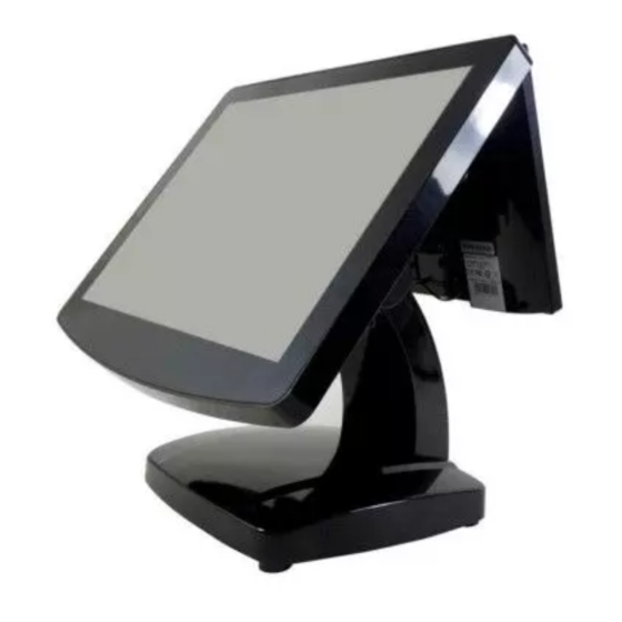
1.3. Parts Descriptions Front View Touch Screen MSR/i-Button Module (Optional) Power Indicator Base Power Switch LED Indicator (Lit when power-on) Rear View Modular Customer Display (Optional) HDD Cover MSR/i-Button Module (Optional) Side I/O Ports Base Rear Cover - 5 -... - Page 13 Side View MSR/i-Button Module (Optional) Side I/O Ports Left View Right View Bottom View (POS Unit) Power Switch Button I/O Ports Bottom View (Base) Power Adaptor - 6 -...
-
Page 14: I/O Ports
1.4. I/O Ports Bottom I/O Ports Side I/O ports (USB) Side I/O Ports - 7 -... - Page 15 I/O Ports Descriptions: I/O Port Description Connect devices with USB connectors. There are 6 external USB ports available, (4 locate on the bottom and 2 left side ports). 2 x USB 3.0 (located on the bottom). 4 x USB 2.0 (2 located on the bottom and 2 on the left side). 1 x mixed PS/2 connector PS/2 1 x 4-pin rounded-power-jack for connecting an AC to DC +12V power adapter.
-
Page 16: Pos Installation
2. POS Installation 2.1. Unpack Your POS The contents may vary with different options. If there’s any physical damage or missing parts, please contact your supplier immediately. Please keep all packing materials in case you need to ship back the device for service. ... -
Page 17: Install Your Pos System
2.2. Install Your POS System The product is a fully integrated POS System and easy for installation. To install the POS System: Place the product on the location. Plug the AC power cord to the POS system Connect the optional peripherals to the POS (for example: Mouse, Keyboard, and Barcode Scanner.) Plug the AC power cord to the power source (for example: electrical outlet). -
Page 18: Plug Ac Power Cord To The Pos
2.3. Plug AC Power Cord to the POS a. Remove the base cover from the base of the POS system. Base Cover b. The power adapter should be found on the bottom of the base (as image left illustrated). Power Adaptor Plug the supplied AC power cord into the power adaptor. -
Page 19: Replace Hard Disk
2.4. Replace Hard Disk HDD Cover (HDD Inside) Remove the securing screw of the HDD cover from the POS unit. Securing Screw HDD Cover b. Remove the HDD Cover from the (HDD Inside) POS unit. Pull the HDD Module to the left to detach it from the POS unit. -
Page 20: Install The Modular Customer Display (Optional)
2.5. Install the Modular Customer Display (Optional) Remove the Top Protective Cover. Top Protective Cover There is a connector for the Modular Customer Display. Top Protective Cover VFD Connector Modular Connect the connector of the Modular Customer Display Customer Display to the POS Unit. Install the Modular Ccustomer Display to the POS Unit. -
Page 21: Configuration Of Modular Customer Display
2.6. Configuration of Modular Customer Display There is a configuration utility to setup your pre-installed customer display (refer to the configuration instruction manual for further information). Please refer to the subfolder “\\Manual\POP-950” and examine the file POP-950_VFD_Customer Display Config Manual_TYSSO_20130201.pdf before configuration. -
Page 22: Bios Setup
3. BIOS Setup The product is compatible with POS Ready, Windows Families (98/2000/XP/7) and Ubuntu Linux. If the drivers are required, find the necessary files in the supplied disc. Plug the AC power cord of the power adapter (CD/DVD-ROM DRIVE) to the power source. Connect an external CD/DVD-ROM DRIVE to the POS system (as the figure below illustrated). -
Page 23: Overview
Overview The BIOS is a program that takes care of the basic level of communication between the CPU and peripherals. It contains codes for various advanced features found in this system board. The BIOS allows you to configure the system and save the configuration in a battery-backed CMOS so that the data retains even when the power is off. -
Page 24: Default Configuration
Default Configuration Most of the configuration settings are either predefined according to the Load Optimal Defaults settings which are stored in the BIOS or are automatically detected and configured without requiring any actions. There are a few settings that you may need to change depending on your system configuration. - Page 25 BIOS MENU Key Function Keys Function Moves the highlight left or right to select a menu. Right and Left arrows Moves the highlight up or down between submenu Up and Down arrows and fields. Exit to the BIOS Setup Utility. <Esc>...
-
Page 26: Main
3.1. Main The Main menu is the first screen that you will see when you enter the BIOS Setup Utility System Date The date format is <day>, <month>, <date>, <year>. <Day> displays a week day, from Sunday to Saturday. <Month>... -
Page 27: Advanced
3.2. Advanced The Advanced menu allows you to configure your system for basic operation. Some entries are defaults required by the system board, while others, if enabled, will improve the performance of your system or let you set some features according to your preference. -
Page 28: Acpi Power Management Configuration
3.2.1. ACPI Power Management Configuration This section is used to configure the ACPI Power Management. ACPI Sleep State Selects the highest ACPI sleep state the system will enter when the Suspend button is pressed. S1 (CSC) Enables the CPU stop Clock function. S3 (STR) Enables the Suspend to RAM function. -
Page 29: Pc Health Status
3.2.2. PC Health Status This section displays the SIO hardware health monitor. Move the cursor to “PC Health Status” and press <Enter> key to access the submenu. The sub menu is as image bellow illustrated: - 22 -... - Page 30 Smart Fan Function CPU Smart Fan Control When this feature is enabled, the CPU’s fan speed will rotate according to the CPU’s temperature. The higher the temperature rises, the faster the speed of rotation. Boundary 1 The temperature range is from 40 to 70. - 23 -...
- Page 31 Tips: How to set the Smart Fan Function 1. Select the “PC Health Status“, and then press <Enter> key to continue. 2. Select the “Smart Fan Function“, and press <Enter> key to confirm. - 24 -...
- Page 32 3. Select “CPU Smart Fan Control“. 4. Select “Enable“ - 25 -...
- Page 33 5. The function is enabled. 6. Select “Boundary 1” and press <Enter>. The pop-up window indicates the selections (temperature range) from 40 to 70. When this feature is enabled, the CPU’s fan speed will rotate faster according to the CPU’s temperature. - 26 -...
- Page 34 7. After the temperature is set, switch the BIOS screen to the “Save & Exit” page. 8. Select “Yes“ and then press <Enter> key to finish the setting of Smart Fan function. - 27 -...
-
Page 35: Cpu Configuration
3.2.3. CPU Configuration This section is used to configure the CPU. It will also display the detected CPU information. Hyper-threading Enable this field for Windows XP and Linux which are optimized for Hyper-Threading technology. Select disabled for other OS not optimized for Hyper-Threading technology. -
Page 36: Sata Configuration
3.2.4. SATA Configuration This section is used to set the options of SATA device. SATA Controller(s) This field is used to enable or disable the Serial ATA channels. SATA Mode Selection This field is used to determine how SATA controller(s) operates. IDE Mode ... - Page 37 If AHCI or RAID mode is selected in the SATA Mode Selection, it will display the following information: Serial ATA Port 0 to Serial ATA Port 3 These fields are used to configure the connected SATA devices. Aggressive LPM Support ...
-
Page 38: Intel Anti-Theft Technology Configuration
3.2.5. Intel Anti-Theft Technology Configuration This section is used to disable Intel Anti-Theft for users to be allowed to login into the platform. It is strict for testing only. Intel Anti-Theft Services in ME is not disabled. Intel Anti-Theft Technology ... -
Page 39: Usb Configuration
3.2.6. USB Configuration This section is used to configure USB parameters. Legacy USB Support Enabled Enable legacy USB. Auto Disables support for legacy when no USB devices are connected. Disabled Keep USB devices available only for EFI applications. EHCI Hand-off ... -
Page 40: F71889 Super Io Configuration
3.2.7. F71889 Super IO Configuration This section is used to configure the I/O functions supported by the onboard Super I/O chip. Restore AC Power Loss When power returns after an AC power failure, the system’s power is off. You must press the Power button to power-on the system. - Page 41 Serial Port 1 Configuration to Serial Port 2 Configuration Serial Port Enable or disable the serial port. Change Settings Select the IO/IRQ setting for the super I/O device. Device Mode Change the serial port mode. Select the “High Speed“ or “Normal Mode“. - 34 -...
- Page 42 Parallel Port Configuration (Reserved) Note: The Parallel port is only avail for the customized version mainboard (with parallel port connector mounted). For specific applications that require the parallel port, please contact the trained personnel prior to the configuration. Parallel Port Enables or Disables the Parallel Port (LPT/LPTE).
-
Page 43: Second Super Io Configuration
3.2.8. Second Super IO Configuration This section is used to configure the I/O functions supported by the onboard Super I/O chip. Serial Port 3 to Serial Port 6 Configurations Port 3 - 36 -... - Page 44 Port 4 Port 5 - 37 -...
- Page 45 Port 6 Serial Port Enable or disable the serial port. Change Settings Select the IO/IRQ setting for the super I/O device. Device Mode Change the serial port mode. Select either the “High Speed “or “Normal Mode“. - 38 -...
-
Page 46: Network Stack
3.2.9. Network Stack This section configures settings relevant to the network stack. - 39 -... - Page 47 Network Stack Enable or disable UEFI network stack. Ipv4 PXE Support When enabled, Ipv4 PXE boot supports. When disabled, Ipv4 PXE boot option will not be created. Ipv6 PXE Support When enabled, Ipv6 PXE boot supports. When disabled, Ipv6 PXE boot option will not be created. - 40 -...
-
Page 48: Cpu Ppm Configuration
3.2.10. CPU PPM Configuration EIST This field is used to enable or disable the Intel Enhanced Speed Step Technology. CPU C3 Report Enabled/Disabled CPU C3 (ACPI C2) report to OS. CPU C6 Report Enabled/Disabled CPU C6 (ACPI C3) report to OS. Config Top Lock ... -
Page 49: Serial Port Control
3.2.11. Serial Port Control This section is used to select the power of serial COM ports. COM 1, COM 2, COM 4 and COM 6 Select Select the power voltage of serial COM ports: 5V, 12V or RI. - 42 -... -
Page 50: Backlight Control
3.2.12. Backlight Control This section is used to select the lightness of backlight. Backlight Step1 is the darkest level. Step8 is the brightest level. - 43 -... -
Page 51: Chipset
3.3. Chipset This field is used to configure the functions of relevant chipset. - 44 -... -
Page 52: Pch-Io Configuration
3.3.1. PCH-IO Configuration Wake on LAN Enable this field to wake up the system via the onboard LAN or via a LAN card that supports the function of remote wake up. After G3 Select the state of AC power when the power is re-applied after a power failure. Power Off / WOL Power-on the system via WOL after G3. - Page 53 PCI Express Configuration PCI Express Clock Gating Enable or disable PCI Express Clock Gating for each root port. PCI Express Root Port 1 to PCI Express Root Port 3 Control the PCI Express Root Port 1 ~ Port 3. - 46 -...
- Page 54 USB Configuration XHCI Pre-Boot Driver Enable or disable the support for XHCI Pre-Boot Driver. XHCI Mode Select the mode to operate the XHCI controller. EHCI 1 and EHCI 2 EHCI 1 and EHCI 2 control the USB EHCI (USB 2.0) functions. One of them must always be enabled.
- Page 55 PCH Azalia Configuration Azalia Select the control detection of the Azalia device. - 48 -...
-
Page 56: System Agent (Sa) Configuration
3.3.2. System Agent (SA) Configuration - 49 -... - Page 57 Graphics Configuration Primary Display Spread is controlled by BIOS. Auto: When the system boots, it will auto detects the display device. IGFX: When the system boots, it will first initialize the onboard VGA. PEG: When the system boots, it will first initialize the PCI Express x16 graphics card.
- Page 58 LCD Control Primary IGFX Boot Display and Secondary IGFX Boot Display The options are VBIOS Default, CRT, and LVDS. LCD Panel Type This field is used to select the type of LCD panel used by the internal graphics device. Type 3: 1024x768 18bit for 15’’...
- Page 59 NB PCIe Configuration Enabled PEG Enables or disables the PEG. Memory Configuration - 52 -...
-
Page 60: Boot
3.4. Boot Setup Prompt Timeout Select the number of seconds to wait for the setup activation key. 65535(0xFFFF) denotes indefinite waiting. Bootup NumLock State This allows you to determine the default state of the numeric keypad. By default, the system boots up with NumLock on wherein the function of the numeric keypad is the number keys. - Page 61 Always Disabling GA20 is not allowed; this option is useful when any RT code is executed above 1 MB. Option ROM Messages This field is used to set the display mode of Option ROM. INT19 Trap Response BIOS reaction on INT19 trapping by Option ROM: Immediate Execute the trap right away.
-
Page 62: Tips: How To Set The Boot Option
Tips: How to set the Boot Option Select “Boot Option #1“ , and then press <+> to make it be the prior boot option Switch to the “Save & Exit” page. Select “Yes” and then press <Enter> key to finish the setting of Boot Option. - 55 -... - Page 63 Hard Driver BBS Priorities Set the order of the legacy devices in this group. CSM Parameters Launch Storage OpROM policy Control the execution of UEFI and legacy storage OpROM. - 56 -...
-
Page 64: Security
3.5. Security Administrator Password Set the administrator password. User Password Set the user password. HDD Security Configuration (reserved) HDD0: Hitachi HTS5: Set the HDD password. Note: This function is functional only for some models of HITACHI’s hard disk drivers. Please contact the personnel of technical support for further information. -
Page 65: Save & Exit
3.6. Save & Exit Save Changes and Reset To save the changes, select this field and then press <Enter>. A dialog box will appear. Select “Yes” to reset the system after saving all changes made. Discard Changes and Reset ... -
Page 66: Updating The Bios
3.7. Updating the BIOS To update the BIOS, you will need the new BIOS file and a flash utility, AFUDOS.EXE. Please contact technical support or your sales representative for the files. To execute the utility, type: A:> AFUDOS BIOS_File_Name /b /p /n then press <Enter>. - Page 67 - 60 -...
-
Page 68: Install The Support Softwares Of Pos Terminal
4. Install the Support Softwares of POS Terminal Please place the supplied disc into the CD/DVD-ROM drive. Browse the DISC and open the folders required to install the driver(s). Double click the folder “Driver & Utility” to access the folder. There are categorized folders for POS Terminal, Peripherals and Touch Screen drivers. - Page 69 There are subfolder of drivers and utilizes for the operating system. User may double-click the icon “Setup” to initiate the Menu and install the appropriate drivers or utilities - 62 -...
- Page 70 Move the cursor to the Utility Menu and click to install the software required ※ Please refer to the manual of the mainboard for detailed instructions (Driver & Utility\POS Terminal Driver\Core i\MANUAL) - 63 -...
-
Page 71: Microsoft .Net Framework 3.5 (For Windows Xp Only)
4.1. Microsoft .NET Framework 3.5 (for Windows XP only) Click “Microsoft .NET Framework 3.5” on the utility menu. Note: Before installing Microsoft .NET Framework 3.5, make sure you have updated your Windows XP operating system to Service Pack 3. There is application software or peripherals/optional devices require the different ... - Page 72 Setup is now installing the driver Setup completed. Click Exit to close the program. - 65 -...
-
Page 73: Intel Chipset Software Installation Utility
4.2. Intel Chipset Software Installation Utility The Intel Chipset Software Installation Utility is used for updating Windows® INF files so that the Intel chipset can be recognized and configured properly in the system. To install the utility, click “Intel Chipset Software Installation Utility” on the menu. Setup is ready to install the utility. - Page 74 Readme file information (for more installation tips). Click “Next” to continue or click “Cancel” to abort the installation. Setup is completed. It’s recommended to restart the system after the driver is installed. Click “Finish” to restart the computer. - 67 -...
-
Page 75: Intel Hd Graphics Driver
4.3. Intel HD Graphics Driver To install the driver, click “Intel HD Graphics Drivers” on the utility menu. Setup is now ready to install the graphics driver. Click Next tip continue. By default, the “Automatically run WinSAT and enable the Windows Aero desktop theme” is enabled. - Page 76 License agreement. Click “Yes” to continue. Readme File Information. Go through the readme document for system requirements and installation tips then click “Next” to continue. - 69 -...
- Page 77 Setup is now installing the driver. Click “Next” to continue. Click “Yes, I want to restart this computer now” then click “Finish” to complete the installation. Restart the system and then the new software installation will take effect. - 70 -...
-
Page 78: Lan Driver
4.4. LAN Driver To install the driver, click “Realtek LAN Drivers” on the menu. Click “Next” to start installing the driver to the computer. Click “Install” to continue the setting process - 71 -... - Page 79 Click “Finish” to finish the installation - 72 -...
-
Page 80: Audio Driver
4.5. Audio Driver Click “Next” to start installing the driver to the computer. The audio driver is successfully installed. It’s recommended to restart the system after the driver is installed. Click “Yes, I want to restart my computer now” then click “Finish” to restart the computer. Restarting the system will allow the new software installation to take effect. -
Page 81: Install The Touch Screen Driver
5. Install the Touch Screen Driver Please place the supplied disc into the CD/DVD-ROM drive. Browse the disc and double click the folder “Driver & Utility” to access the folder. There are categorized folders for POS Terminal, Peripherals and Touch Screen drivers. - 74 -... -
Page 82: Install The Driver Of Resistive Type Touch Panel
5.1. Install the Driver of Resistive Type Touch Panel To install the drivers of Resistive Touch Panel: Double click the folder “Touch Driver” to access the subfolder. There are drivers of Resistive type and SAW type touch screen. To install the driver for Resistive type, select (double click) the folder “Resistive Touch”... - Page 83 Click “Next” to start the installation. License Agreement. Click “I accept the terms of the license agreement” and click “Next” to continue. - 76 -...
- Page 84 Setup Type: PS/2 Interface (reserved). This is reserved for Extra PS/2 Interface version only. Leave the check box UNMARKED. Click “Next” to continue. Setup Type: RS-232 Interface (reserved): This is reserved for RS-232 Interface version only. Leave the check box UNMARKED. Click “Next”...
- Page 85 Setup Type: Calibration after system reboot: Click the checkbox “None” and click “Next” to continue. There is a pop-up dialogue. Click “Ok” to continue. - 78 -...
- Page 86 m. Setup Type: Support Multi-monitor System: Click the checkbox “Support Multi-Monitor System” and click “Next” to continue. Choose Destination Location: Click “Browse to change the different destination folder. Note: It’s recommended to use the defined location and install the driver. Click “Next”...
- Page 87 Select Program Folder: Use the pre-defined setting and click “Next” to continue. Create Shortcut on the desktop: Click the checkbox and click “Next” to continue. - 80 -...
- Page 88 Now the software is installing to the system. - 81 -...
- Page 89 4-Point Calibration. Click “Yes” to perform touch screen calibration. Touch the first calibration mark on the edge of the screen. There is a beep sound to indicate the point is calibrated. Proceed to the next mark and perform all 4 calibration points to complete the calibration. Installation completed.
-
Page 90: Touch Screen Calibration (Resistive Type)
5.2. Touch Screen Calibration (Resistive Type) After the driver is installed to the system, there is a shortcut on the desktop for touch screen Calibration. User can re-configure the touch screen by initiating the utility. To calibrate the touch screen: Double click the icon to access the utility. - Page 91 Tap the calibration mark on the bottom-left to complete the first calibration point. There is a beep sound to indicate the point is calibrated. Proceed to the next mark and complete all calibration points The calibration is completed; Click “OK” to continue. - 84 -...
- Page 92 Tips: Advanced 9-point/25-point Calibration There are advanced 9-point calibration and 25-point calibration for more accurate calibration demands. Access “Setting” submenu, and select “Linearization Style” (9 Points or 25 Points) to calibrate your touch screen. - 85 -...
- Page 93 Access “Tools” submenu, and select “Linearization” to calibrate your touch screen. Tap the calibration mark on the bottom-left to complete the first calibration point. There is a beep sound to indicate the point is calibrated. Proceed to the next mark and complete all calibration points (9 Points or 25 Points). - 86 -...
-
Page 94: Peripherals Test
6. Peripherals Test The POS terminal is equipped with mainstream interfaces for the connection of peripherals and devices. If the POS is equipped with optional peripherals (for example: Wi-Fi module, magnetic stripe card reader, customer display, or a cash drawer). Please install the driver or perform the tests prior or to the POS system is operational. -
Page 95: Install The Wi-Fi Driver (Optional)
6.1. Install the Wi-Fi Driver (Optional) There are categorized subfolders for POS Peripherals. Select “WiFi” to access the subfolders. Open the folder “LR802UKN3(USB)”to access the subfolders: Open the folder to find the appropriate driver. Access the subfolder and double click the icon to install the driver. Click “Yes”... - Page 96 Select “Install driver only” and click “Next” to continue. Click “Install” to begin Installation. - 89 -...
- Page 97 The Wi-Fi driver is successfully installed. Click “Finish” to complete and exit the Wizard Note: To access the wireless network and initiate the connection, please refer to the service provider for further information. - 90 -...
-
Page 98: Test Your Magnetic Stripe Card Reader(Msr) And I-Button Module
6.2. Test Your Magnetic Stripe Card Reader(MSR) and i-Button Module Execute Start >> All Programs >> Accessories >>Notepad. MSR Test: Swipe a card through the reader and the information will be displayed on the window - 91 -... - Page 99 i-Button Test: Attach the i-button to the reader and the information will be displayed on the window - 92 -...
-
Page 100: Test Your Customer Display
6.3. Test Your Customer Display There are categorized subfolders for POS Peripherals. Select (double click) the subfolder “Customer Display”. There are two folders for LCD type Customer Display (DSP) and Vacuum Fluorescent type Display (VFD). Select the folder by the Customer Display installed. Select the subfolder “Test Utility”. - Page 101 The Communications Window pops up and ready for test. Enter any keys on the window and the texts will display on the customer display The texts are displayed on the customer display. To terminate the program, click (X) to close the Communications Window. There is a pop up window for notice.
-
Page 102: Test Your Cash Drawer
6.4. Test Your Cash Drawer There are categorized subfolders for POS Peripherals. Select “Cash Drawer” and access the subfolders There are two folders as below. Select the folder “Test Software” and access the subfolders. Select the folder “Core I” and access the folder. Double click the file “CASH_DRAWER”... - Page 103 - 96 -...
-
Page 104: Appendix
7. Appendix Mainboard Technical Document The settings of the mainboard are factory preset values and need not adjust for most applications. Please reserve the settings, installation and maintenance to the qualified personnel only. For the detailed information relating to the mainboard configurations, please refer to the manual of the mainboard for detailed instructions. -
Page 105: Com Ports Pin Assignment
COM Ports Pin Assignment External COM Ports Setting (COM 1/2/4/6) Configure the external serial ports in the Advanced menu of the BIOS Setup Utility (see “3.2.11Serial Port Control”). - 98 -... -
Page 106: Com 5 Jumper Setting (Jp19)
COM 5 Jumper Setting (JP19) - 99 -... -
Page 107: Cash Drawer Power Select (J3)
Cash Drawer Power Select (J2) - 100 -... -
Page 108: Jumper Location And Settings
Jumper Location and Settings - 101 -... -
Page 109: Jumper Settings
Jumper Settings - 102 -... - Page 110 - 103 -...
- Page 111 05102014 - 104 -...
Need help?
Do you have a question about the POS-6000-i and is the answer not in the manual?
Questions and answers