Table of Contents
Advertisement
Quick Links
Advertisement
Table of Contents

Related Manuals for Tysso POSpark 5700 Series


Summary of Contents for Tysso POSpark 5700 Series
- Page 1 User’s Manual POSpark 5700 Series...
-
Page 2: General Information
General Information ABOUT THIS MANUAL The purpose of this user’s manual is to provide general information on TYSSO POSpark Series POS terminal and to show the users how to configure the hardware-related configurations. The information in this manual is subject to change without notice due to rapid improvement on IT technology. -
Page 3: Important Notice
Warranty does not cover any damage caused by improper use. TRADE MARKS AND SERVICE MARKS TYSSO is a registered trademark of FAMETECH INC. Other brand and product names are trademarks and registered trademarks and service marks of their respective owners. -
Page 4: Important Safety Information
2. Liquid is spilled into the system. 3. The system is dropped or the cabinet is damaged. When the system is not in use, cover the system and store it with care. Version 1.0 © Copyright Fametech Inc. (TYSSO) 2008... -
Page 5: Table Of Contents
Contents General Information ........................ii ABOUT THIS MANUAL....................ii DISCLAIMER ........................ii WARNING ...........................ii IMPORTANT NOTICE ......................iii IMPORTANT SAFETY INFORMATION................iv 1. Introduction ..........................2 1.1 Unpacking ........................2 1.2 System Overview ......................2 1.3 I/O Ports ......................... 5 1.4 Specifications ......................... 5 2. -
Page 6: Introduction
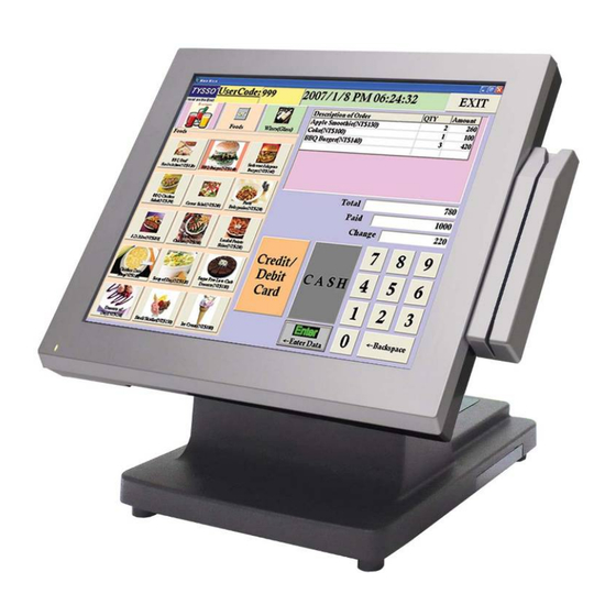
1. Introduction 1.1 Unpacking The contents may vary with different options. If there’s any physical damage or missing parts, please contact your supplier immediately. Please keep all packing materials in case you need to ship back the device for service. POSpark main system HDD (2.5”, pre-installed) / Compact Flash (CF, pre-installed) / Disk on Module (DOM, pre-installed) - Page 7 Rear View Bottom View Side View...
- Page 8 Options:...
-
Page 9: I/O Ports
1.3 I/O Ports Port Description Connect devices with USB connectors. There are 2 internal USB ports reserved and one external port is for connecting touch panel. Mouse PS/2 Mouse Connector PS/2 Keyboard Connector A 4 din rounded-power-jack for connecting an AC to DC +12V power adapter. PWR IN COM 1/2/4 can provide RI, +5V, or +12V on pin 9 by switching the power POWERED COM... - Page 10 Model POS-5717 POS-5715 POS-5712 Main Board Intel Celeron M 1.0GHz BGA Type Core Logic Intel 852GM + ICH4 System Memory 200-pin SODIMM, DDR266/333, 256MB/512MB/1GB OS Support Win2000, NT, Win XP Pro, WinCE, WEPOS Display TFT LCD 17” 15” 12.1” Brightness 300 nits 250 nits 180 or 400 nits...
-
Page 11: Components & Peripherals Installation
2. Components & Peripherals Installation 2.1 Replace Hard Disk a. Lift the cover from the upper side edges as marked by the circles and push it down to remove it. b. Lossen the screw x 4 on the VESA bracket. c. - Page 12 d. Remove the panel from the VESA bracket. e. Loosen the screw on the cover of the hard disk bay to remove the cover. f. Loosen the spacer. g. Hold the hard disk and take it out in the direction. Then unplug it from the connector.
-
Page 13: Install Second Display
h. Loosen the 4 screws to remove the hard disk from the bracket. Then install the new hard disk following the above steps with the order reversed. 2.2 Install Second Display a. Hold the second display and turn the system over carefully. Pass the cord through the holes in the directions of the arrows. -
Page 14: Install Pole-Type Customer Display
2.3 Install Pole-type Customer Display a. Pass the cord of the customer display through the holes in the directions of the arrows. Plug the cable to a free COM port and connect the extension power cable. b. Press the stand of the customer display into place. -
Page 15: Operating System
3. Operating System The POSpark main board is compatible with Windows 95/98/2000/XP and Red Hat Linux 9.0. If the drivers are required, find the necessary files in the “POS & Auto/ID Peripherals” CD through CD-ROM/Driver/POS. The storage media can be HDD, Compact Flash (CF), or Disk on Module (DOM) depending on different options. -
Page 16: Adjust Cpu Fan Mode And Brightness
d. Select “1 Boot Device” and press the key. Press the key to select “USB: External CD-ROM.” Press the <F10> key to save and exit the setting. e. After the system reboots, it will start to install the operating system from the CD. 3.2 Adjust CPU Fan Mode and Brightness a. - Page 17 b. Select “Advanced.” Select “Harware Health Configuration” and press the <Enter> key to go to the sub screen. c. Select “CPU Fan Mode” and press the <Enter> key. There are 3 modes for options: Full On mode makes the CPU fan run at its full speed. Automatic mode is not available.
- Page 18 d. Select “PWM Duty control.” Adjust the brightness by entering a number ranges from Min 20 to Max 127. The highter the value, the brighter the screen will be. e. After configuring the setting, press the <F10> key to save and exit the setting. The system will reboot automatically.
-
Page 19: Drivers Installation
4. Drivers Installation 4.1 Install Chipset Driver a. Double click the folder “852gm” and then the file “win2k_xp141950” to start the installation. b. Click “Next” as the window pop up. c. Click “Next.” d. Click “Yes” on the License Agreement window to accept the terms. -
Page 20: Install Audio Driver
e. Click “Finish” and restart the system. 4.2 Install Audio Driver a. Double click the folder “audio” and the file “WDM_A398” to start the installation. b. Click “Next” on the Audio Setup window. c. Click “Finish” and restart the system. -
Page 21: Install Lan Driver
4.3 Install LAN Driver a. Double click the folder “LanSetup” and then the file “Setup” to start the installation. b. Click “Next” on the welcome window. c. Click “Finish” to finish the installation. -
Page 22: Install Touch Screen Driver
4.4 Install Touch Screen Driver a. Double click the folder “Dirver” and then double click the subfolder according to the operating system. b. Double click the file “setup” to start the installation. c. Click “Next” on the welcome window. - Page 23 d. Select the destination folder and click “Next.” e. Click “Next” without selecting the 2 items. f. Click “Install” to start the installation.
- Page 24 g. Click “Finish” to exit the setup. h. Double click “Touch package” and then click “4 pts. calibration” to start the 4-point-calibration. Or select “Advance” to select “9 pts. linearization” or “25 pts. linearization”. The more points are calibrated, the more accurate the calibration will be.
-
Page 26: Peripherals Testing
i. Touch the red dot on the screen with a finger till it disappears. The dot will appear 4/9/25 times in turn on the screen. j. After the calibration is done, press the lower button to save. 5. Peripherals Testing If the POSpark is equipped with magnetic stripe card reader or customer display, connected to a cash drawer, follow the steps below to test the function. -
Page 27: Customer Display
b. After the testing window pops up, slide a magnetic stripe card and its information will show on the window. 5.2 Customer Display a. Open the folder “RS-232 Testing” and double click the file “BREAKOUT.” b. Enter any keys on the window and the typed words will appear on the customer display. -
Page 28: Cash Drawer
5.3 Cash Drawer a. Open the folder “Cash Drawer” and double clik the file “setup.” b. Click “OK” on the welcome window. c. Select the destination folder and click the icon to start the installation. d. Select an existed group name or enter a new one. Click “Continue.”... - Page 29 e. Click “OK” to finish the installation. f. Execute Start >> All Programs >> Cash Drawer >> CashDrawer to open the program. g. Click “Open Cash Drawer” on the window, and the connected cash drawer will open.
- Page 30 Note: The above cash drawer driver is for testing only. If editing AP Open drawer is required, please refer to the following command set. Cash Drawer Controller Register Register Location: I/O port 280h Attribute: Read/Write Size: 8 bit Bit 0~3, 5~7: Reserved Bit 4: Cash Drawer “DIO OUTPUT”, pin output control.
-
Page 31: Jumper Settings & Connectors
6. Jumper Settings & Connectors 6.1 Jumper Settings • JP3: Clear CMOS setup Description Normal Operation Clear CMOS Setup • JP5: LCD voltage setup Description 3.3V • JP4: K/B use selection Description K_DAT and K_DAT_A K_CLK and K_CLK_A Use for K_DAT and K_CLK •... -
Page 32: Connectors
6.2 Connectors • AUX1 Audio Jack-in connectors Pin No. Description Line-out-R Line-out-L • CN5: Audio Header Connector Pin No. Description Line-out-L Line-out-R • CN12 ATX 4PIN Power Connectors Pin No. Description • CN9: RJ-11 DIO Connectors Pin No. Description DIO OUTPUT DIO INPUT •... - Page 33 DATA 6 DATA 9 DATA 5 DATA 10 DATA 4 DATA 11 DATA 3 DATA 12 DATA 2 DATA 13 DATA 1 DATA 14 DATA 0 DATA 15 GROUND IDE DRQ GROUND IOW# GROUND IOR# GROUND IDE CHRDY GROUND IDE DACK GROUND INTERRUPT 66DET...
- Page 34 • CF1: Compact Flash Connector Pin No. Description Pin No. Description GROUND VCC-IN CHECK1 DATA 3 DATA 11 DATA 4 DATA 12 DATA 5 DATA 13 DATA 6 DATA 14 DATA 7 DATA 15 HDC_CS1# HDC_CS3# GROUND IOR# IOW# VCC_COM IRQ15 VCC_COM VCC_COM...
- Page 35 DSR1 RTS1 CTS1 • COM2: Serial Port Connector Pin No. Description DCD2 DTR2 DSR2 RTS2 CTS2 • COM4: Serial Port Connector Pin No. Description Pin No. Description DCD4 DSR4 RTS4 CTS4 DTR4 • COM5: Serial Port Connector Pin No. Description Pin No.
- Page 36 Pin No. Description KDATA_A VCC5 K_CLK_A • PS2: Mouse Jack Connector Pin No. Description MDATA VCC5 MCLK • CN15: USB CN3 & KB1 & PS2 Connector Co-lay Pin No. Description Pin No. Description USB_POWER D1F+ D0F- D1F- D0F+ USB_POWER K_POWER MDATA KDATA_A MCLK...
- Page 37 VCC5 KDATA_A K_CLK_A K_DAT K_CLK COM3_TX COM3_RX KB_EN • CN3A: USB Connector Pin No. Description USBVCC1 D0F- D0F+ USBGND1 • CN3B: USB Connector Pin No. Description USBVCC1 D1F- D1F+ USBGND1 • CN4A: USB Connector Pin No. Description USBVCC2 D2F- D2F+ USBGND2 •...
- Page 38 D4F+ D4F- USBVCC3 • USB2: USB Connector Pin No. Description Pin No. Description D5F+ D5F- USBVCC3 • LAN1: 100M-LAN RJ45 Connector Pin No. Description Pin No. Description V_DAC V_DAC LINK100- LINK100+ ACT- ACT+ • VGA1: 16-pin CRT Connector Pin No. Description Pin No.
- Page 39 • CN8: Inverter & Power Button Connector Pin No. Description VCC12 VCC12 LCD_EABLE LCD_BKLTEN Power Button- • CN1: Inverter Connector Pin No. Description VCC12 LCD_EABLE LCD_BKLTEN • LVDS1: LCD LVDS Interface Connector Pin No. Description Pin No. Description VCC_LCD VCC_LCD VCC_LCD VCC_LCD LVDSA0+...
- Page 40 LVDSACLK- LVDSBCLK- LVDSA3+ LVDSB3+ LVDSA3- LVDSB3- • FAN1: Fan Connector Pin No. Description Fan Speed Detect +12V • FAN2: Fan Connector Pin No. Description Fan Speed Detect +12V • FAN3: Fan Connector Pin No. Description +12V • CN10: LED Connector Pin No.
- Page 41 Pin No. Description RESET • DIMM1: DDR SODIMM SOCKET...
Need help?
Do you have a question about the POSpark 5700 Series and is the answer not in the manual?
Questions and answers