Table of Contents
Advertisement
Quick Links
Advertisement
Table of Contents

Related Manuals for Terasic ArduCam IMX519


Summary of Contents for Terasic ArduCam IMX519
- Page 1 User Manual www.terasic.com 1.1. Q October 14, 2024...
-
Page 2: Table Of Contents
2.1 Features ..................... 4 Chapter 3 Camera connection setup ............7 3.1 Replacement of 22-pin FPC Cables ............7 3.2 Connecting the Camera Module to the Terasic FPGA Board ....12 Chapter 4 RTL Example Codes ............. 16 4.1 MIPI_CSI2_CAMERA RTL ............... 16 Chapter 5 VVP Based Example Codes .......... -
Page 3: Chapter 1 Overview
Overview This manual provides a comprehensive guide for connecting the 16MP IMX519 MIPI CSI-2 Camera Module to Terasic FPGA boards which have MIPI connectors. It covers the hardware connection setup, and a basic demo application for image acquisition. The MIPI CSI-2 interface is a high-speed serial interface commonly used for image sensor communication. -
Page 4: Camera Module Specification
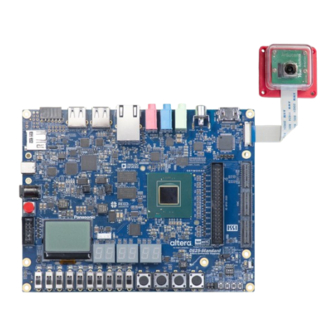
Image Sensor IMX519 Resolution 16MP Optical Size 1/2.53'' Active Pixels 4656(H) × 3496(V) 1.22μm × 1.22μm Pixel Size CSI-2 Data Output 2-lane mode Shutter Type Rolling Shutter Color Filter Array Quad-Bayer RGB Frame Rate 4656x3496@10fps, User Manual www.terasic.com October 14, 2024... - Page 5 Field of View(FOV) 80°(D) IR Sensitivity Integral IR-cut Filter Camera Board Size 24 x 25mm Compatibility Terasic Atum A5 board Terasic DE25-Standard board Connect ATUM A5 Figure 2-2 Connect to Atum A5 board. Connect DE25-Standard User Manual www.terasic.com...
- Page 6 Figure 2-3 Connect to DE25-Standard board. User Manual www.terasic.com October 14, 2024...
-
Page 7: Camera Connection Setup
3.1 Replacement of 22-pin FPC Cables Figure 3-1 shows the 15-22 pin and 22-22 pin FPC cables provided by the camera module manufacturer. To connect to the MIPI connector on the Terasic FPGA development board, the 22-22 pin FPC cable is required. If your camera module is... - Page 8 Figure 3-2 Camera module with 15-22 pin FPC cable Replacing Steps Remove the plastic cover from the camera module. Figure 3-3 Remove plastic cover Use your fingernail or a small tool to gently open the FPC connector's slider-lock. User Manual www.terasic.com October 14, 2024...
- Page 9 Ensure the cable is correctly oriented, when the camera is placed face up, the connection method is that the silver contacts of the flexible cable face down to connect to the camera. User Manual www.terasic.com October 14, 2024...
- Page 10 Carefully insert the cable straight into the connector’s slot. Push it in gently until it reaches the end, ensuring it is seated evenly without bending or damaging the cable. Figure 3-7 Insert the cable Slide the locking bar forward (towards the cable) to lock it. User Manual www.terasic.com October 14, 2024...
- Page 11 Place the plastic cover back to the camera module and secure it. Make sure the FPC cable is routed through the notch in the plastic cover. Figure 3-9 Place the plastic cover back Figure 3-10 shows the camera module with the 22-22 pin cable installed. User Manual www.terasic.com October 14, 2024...
-
Page 12: Connecting The Camera Module To The Terasic Fpga Board
Figure 3-10 Camera module with 22-22pin FPC cable 3.2 Connecting the Camera Module to the Terasic FPGA Board As shown in the figure below, use your fingernail or a small tool to gently open the FPC connector's slider-lock. (Here we use DE25-Standard board as example, user may need to remove the top plastic cover of the board.) - Page 13 Carefully insert the cable straight into the connector’s slot. Push it in gently until it reaches the end, ensuring it is seated evenly without bending or damaging the cable. Figure 3-13 Insert the cable Slide the locking bar forward (towards the cable) to lock it. User Manual www.terasic.com October 14, 2024...
- Page 14 Figure 3-14 Lock the FPC connector's slider-lock Figure 3-15 Figure 3-16 shows the camera module has connected with the Terasic FPGA board. Figure 3-15 Connect to DE25-Standard board. User Manual www.terasic.com October 14, 2024...
- Page 15 Figure 3-16 Connect to Atum A5 board. User Manual www.terasic.com October 14, 2024...
-
Page 16: Rtl Example Codes
Chapter 4 RTL Example Codes This chapter provides instructions on how to capture a ArduCam IMX519 image (resolution is 1920X1080@60 Hz) and use on-chip storage methods (Frame-Buffer) to display the image on a HDMI Monitor. These storage methods realized by pure Verilog HDL language have been validated on Atum-A5 board. - Page 17 HDMI_controller (vpg.v): This module serves as the LCD signal timing generator, capable of producing 1080P@60Hz signal timing. It also provides a color bar video pattern output. Auto_Focus (FOCUS_ADJ.v): This module performs high-frequency component User Manual www.terasic.com October 14, 2024...
- Page 18 Hardware Setting Up 1. As shown in figure below, connect the Atum A5 board to the camera module and HDMI monitor for image capturing and display. User Manual www.terasic.com October 14, 2024...
- Page 19 Figure 4-2 Hardware setup for Atum A5 board. 2. Connect power cable and USB type-C cable to the Atum A5 board. Figure 4-3 Hardware setup for Atum A5 board. User Manual www.terasic.com October 14, 2024...
- Page 20 Lights up when HDMI IC(ADV7513) I2C setting is successful LED2 Lights up when Auto-Focus finish LED3 Lights up when ArduCam IMX519 I2C setting is successful BUTTON0 White Balance BUTTON1 Auto Focus BUTTON2 Reset to Initial BUTTON3 Press for displaying color bar on LCD screen User Manual www.terasic.com...
-
Page 21: Vvp Based Example Codes
Altera’s Video and Image Processing (VIP) suite. The Demosaic IP is used to decoder Bayer Pattern to RGB video. Note, the Demosaic IP only supports Lite mode, so the other IP also be configure as lite mode to consistent with User Manual www.terasic.com October 14, 2024... - Page 22 Nios V Project is located in the software folder. The NIOS Program will show demo configuration menu for user to change register setting as shown Figure 5-2. Table 5-1 shows the function detail about the menu. User Manual www.terasic.com October 14, 2024...
- Page 23 Dump sensor major register setting. [8]Focus: Set Position Set VCM position for image focus. To adjust the VCM position, increase the value by [9]Focus: Scan 64 each time, starting from 0 and going up to User Manual www.terasic.com October 14, 2024...
-
Page 24: Vvp_Mipi_Csi2_Imx519 For Atum A5
Connect a USB Type-C cable between the host PC and the USB connector (J6) on the Atum A5 board (See Figure 5-3). Connect MIPI CSI-2 Camera Module to MIPI-1 Connector (J8) on FPGA board. User Manual www.terasic.com October 14, 2024... -
Page 25: Vvp_Mipi_Csi2_Imx519 For Atum A5
Figure 5-3 VVP_MIPI_CSI2_IMX519 demonstration setup for Atum A5 5.3 VVP_MIPI_CSI2_IMX519 for Atum A5 Demonstration Source Code Project directory: Demonstrations\de25-standard\VVP_MIPI_CSI2_IMX519 Nios V project workspace: VVP_MIPI_CSI2_IMX519\software Demo batch file folder: VVP_MIPI_CSI2_IMX519\demo_batch User Manual www.terasic.com October 14, 2024... - Page 26 14. The HDMI Monitor will start showing the video captured from the camera. 15. Nios V terminal will show the demo configuration menu as shown in Figure 5-2. Table 5-1 summarizes the functional keys. Figure 5-4 VVP_MIPI_CSI2_IMX519 demonstration setup for Atum A5 User Manual www.terasic.com October 14, 2024...
-
Page 27: Chapter 6 Additional Information
Chapter 6 Additional Information 6.1 Getting Help Here are the addresses where you can get help if you encounter problems: Terasic Technologies No.80, Fenggong Rd., Hukou Township, Hsinchu County 303035. Taiwan Email: support@terasic.com Web: www.terasic.com Atum A5 Web: agilex-som.terasic.com ...
Need help?
Do you have a question about the ArduCam IMX519 and is the answer not in the manual?
Questions and answers