Table of Contents
Advertisement
Quick Links
Advertisement
Table of Contents
Troubleshooting

Subscribe to Our Youtube Channel
Related Manuals for micro-trak MT-2405 F


Summary of Contents for micro-trak MT-2405 F
- Page 1 MT- 2 405 AUTOMATIC RATE CONTROLLER REFERENCE MANUAL...
- Page 2 This manual is written for the MT-2405 F, Model MT24F-99-LR, which may be used for either English or Metric mea sure ment. Please read the manual carefully and follow the instructions as they apply to your usage.
-
Page 3: Warranty
* Some limitations apply. See warranty statement for details. At Micro-Trak Systems, we believe a product that delivers quality and performance at a low cost is what is needed to help today’s operator and the operator of the future compete in the world mar ket. -
Page 4: Table Of Contents
Component Parts and Assembly Hardware ..........................7-8 Installation ......................................9-20 Required Tools ..........................................9 Mounting the Display Console ...................................9 Mounting the Micro-Trak Switch Box (if used) .............................9 Electrical Installation .....................................10-11 Universal Switch Harness ..................................10-11 Micro-Trak Switch Box Harness ..................................12 Micro-Trak Switch Box Harness Connection .............................. 13 Speed Sensor Installation ....................................14-16... -
Page 5: Table Of Contents
Servo Valve Control Signal ....................................39 Servo Valve, Plumbing ......................................40 Plumbing Troubleshooting Chart .................................. 40 Wiring Diagram - Universal Switch Harness ..........................37 Wiring Diagram - Micro-Trak Switch Box Harness ........................38 Plumbing Guidelines ..................................41-42 General ............................................. 41 Pump Inlet ..........................................41 Agitation .......................................... -
Page 6: Basic Overview Of Typical Installation
Basic Overview of Typ i cal Installation Hall-e ect Speed Sensor Magnets on Hub of Non-driven Wheel Remote Run/Hold MT-2405F Console Harness Connection Micro-Trak Boom Ignition Control Switch Box Agitation Shot-o Valve * Main Harness Hitch Connectors Stainer * Trottle Valve *... -
Page 7: Component Parts And Assembly Hardware
Component Parts and Assembly Hardware Before beginning installation, check the carton contents for the following items: MT- 2 405 AUTOMATIC RATE CONTROLLER REFERENCE MANUAL MT-2405 F Console Reference Manual 10’ 3-Pin W/P Extension Model MT24F-99-LR P/N 13756 Cable P/N 10449 P/N 13755 5’... - Page 8 Relay Connection flow harness P/N 13757 Speed Flow (yellow tie) (green tie) Run/Hold (gray tie) Component Parts for Micro-Trak Switch Box (Optional Equipment) To Console 15-Pin Mate-n-Lock Battery (+ Org) Ground (- Blu) Ignition MT Switch Box Main Harness 9-Pin Mate-n-Lock...
-
Page 9: Installation
Mount knob tra tion 1B. Console easily adjusts for side or dashboard mounting. Mounting the Micro-Trak Switch Box (if used) Select a mounting location which seems most workable, Illustration 2A and that best fits your needs. It should be con ve nient to reach and high ly vis i ble to the op er a tor. -
Page 10: Installation (Cont)
Micro-Trak Switch Box Harness instructions on page 13. Your MT-2405 F is equipped with an elec tron ic mem o- The MT-2405 F must be connected to a 12-volt DC negative ry which does not re quire a con stant sup ply of pow er to ground electrical system. - Page 11 For Ball valves, connect to the switch terminal that is HOT Connect the boom detect wires from the MT-2405 F when the valve is ON (open), and ground when the valve is harness to the wires on the shut-off valve harness that OFF (closed).
-
Page 12: Micro-Trak Switch Box Harness
Your MT-2405 F is equipped with an elec tron ic mem o ry which source and directly to the battery. does not re quire a con stant sup ply of pow er to re tain dai ly First, using your test light, locate a terminal or wire connected to tals or cal i bra tion val ues. -
Page 13: Micro-Trak Switch Box Harness Connection
12) to protect the circuit. Connect the ORANGE wire to the positive battery terminal. Connect the Micro-Trak Switch Box to the MT-2405 F console by plugging the 10-pin M/P tower from the switch box into the 10-pin M/P shroud of the display console. See Illustration 6 on page 12. -
Page 14: Speed Sensor Installation
(meters). Divide that measurement number of magnets required is 6. Illustration 9C The magnets provided by Micro-Trak are marked with a Illustration 9A punched dashed line on the SOUTH pole side of the magnet. 1” Minimum See Illustration 9A. -
Page 15: Attaching Magnets
45° max MT-2405 F console every time a magnet passes by the tip of 3/8” nuts the speed sensor. For the speed sensor to operate properly,... -
Page 16: Speed Sensor Options
Dickey-John GPS speed sensors. An adapter cable may SEE APPENDIX I FOR LIST OF ADAPTER CABLES FOR RADAR. be required. Contact a Micro-Trak dealer/distributor for de tails on any of these products, or call Mi cro-Trak Systems, Inc. at 1-800-328-9613. -
Page 17: Mounting And Plumbing Flowmeter
Installation (cont) Illustration 12 Mounting and Plumbing Flowmeter Hose Clamps* Sprayer Line* ¾” NPT Male Fitting* The Flowmeter must be installed in the main boom line after any strainers, return lines, or valves. Se cure ly mount flow me- Flowmeter Hose Clamps* ter (hardware not supplied) in a vertical position in an area Sensor... -
Page 18: Manual Pressure Relief Valve
Installation (cont) Illustration 14 Pressure Manual Pressure Relief Valve Relief Valve Tee “C” If you have a positive displacement pump or a cen trif u gal pump capable of generating excessive pressure, you must in stall a pressure relief valve and adjust it to a safe max i- mum pressure. -
Page 19: Pressure Relief Valve (Electric)
Clamp the supplied quick disconnect wire tap over the WIRING INSTRUCTIONS 9” BLUE wire (Pin A) of the MT-2405 F Speed, run/hold, flow harness. Snap the female spade terminal over the Fasten the supplied relay in a suitable location. Use a... -
Page 20: Remote Run/Hold
Installation (cont) Remote Run/Hold Illustration 20 BLACK TIES YELLOW TIE RELIEF COTROL 20 GA. BLU 20 GA. BRN SPEED POWER 20 GA. RED 18 GA. WHT 3-PIN SPEED SIGNAL 20 GA. ORG 18 GA. RED M/P 150 TOWER SPEED GROUND 18 GA. -
Page 21: Console Functions
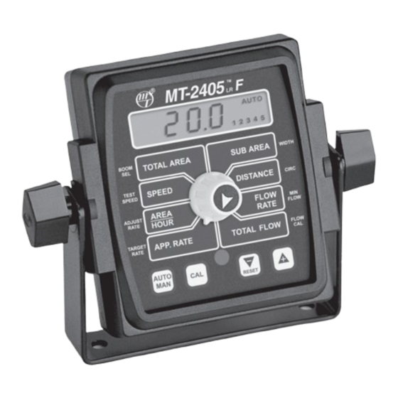
MT-2405 F Console Func tions The MT-2405 F features a large, easy-to-read liquid crystal display, lighted Brite-Knob rotary dial ™ and lighted panel for night use. TOTAL AREA: SUB AREA: Keeps a running count of the total acres Counts acres (hectares) worked. Can be used to (hectares) worked. -
Page 22: Plumbing Overview (Universal)
MT-2405F System Layout Universal Harness... -
Page 23: Plumbing Overview (Switch Box)
MT-2405F System Layout Micro-Trak Switch Box Harness... -
Page 24: Valve Diagrams
MT-2405F Valve Diagrams Range Illustration 21 Adjust Valve For Oversized Pumps Tee “C” Tee “A” Illustration 22 Pressure For Positive Displacement Pump Relief Valve Tee “C” Tee “A” Illustration 23 If Optional Relief Valve Kit is Used Servo Valve Relief Valve Tee “B”... -
Page 25: Calibration
Illustration 24 English or Metric? MT2405 F ™ The MT-2405 F is capable of displaying in for ma tion in Amer i- MANAUTO can En glish or standard Metric measurement. The MT-2405 F CALHOLD is shipped from the factory programmed for English. -
Page 26: Entering Calibration Values
Calibration BOOM SEL: This po si tion is used to se lect the boom sec- (cont) tion to be cal i brat ed. With the ro ta ry switch in this po si- Entering Calibration Values tion, the display will show the active boom section BOOM TOTAL AREA... -
Page 27: Determining Wheel Circumference
Calibration (cont) Entering Calibration Values (cont) Illustration 26 CIRC: This position is used to calibrate the speed sensor for ac cu rate speed and dis tance measurement. When this MT2405 ™ position is selected, the display will alternately show, every three seconds, the wheel circumference value and the MANAUTO CALHOLD... -
Page 28: Flowmeter Calibration Tag
Your Micro-Trak flowmeter has been tested at the factory and assigned a “FLOW CAL” value to make it operate properly with the MT-2405 F console. This number is stamped on the metal tag attached to the flowmeter. See Illustration 28. This is a starting point only. -
Page 29: Fine-Tuning Speed/Distance Calibration Value (Without Remote Run/Hold Kit)
Calibration (cont) Fine Tuning Speed/Distance Calibration Val ue - Without Remote Run/Hold Kit When the display shows distance (“CAL” is not This procedure is used to verify the calibration of systems WITHOUT an optional remote run/hold kit installed. In displayed), ver i fy wheth er the number displayed is the order to achieve accurate measurements, each step in this ex act dis tance you drove (with in “+”... -
Page 30: Fine-Tuning Speed/Distance Calibration Value (With Remote Run/Hold Kit)
Calibration (cont) Fine Tuning Speed/Distance Calibration Val ue - With Remote Run/Hold Kit This procedure is used to verify the calibration of systems When the display shows distance (“CAL” is not WITH an optional remote run/hold kit installed. In order to displayed), ver i fy wheth er the number displayed is the achieve accurate measurements, each step in this fine tuning ex act dis tance you drove (with in “+”... -
Page 31: Fine-Tuning Flowmeter Calibration
Calibration (cont) Fine Tuning Flowmeter Calibration Val ue This procedure is used to verify and fine-tune the Once the display again begins alternating, you will flowmeter calibration. Every flowmeter is calibrated notice that the flowmeter calibration value has changed. with water at the factory and stamped with a calibration If the TOTAL FLOW value is correct, write down the new val ue. -
Page 32: Test Speed
“Pre-field” checks. When a typical operating speed valve (must be installed). is entered, the MT-2405 F will respond as if you were actually driving that speed. It allows you to simulate your spraying Start vehicle and pump, bring the engine up to normal application with plain water, while remaining stationary, to operating RPM. -
Page 33: Operation
Operation Console Switches and Buttons CONSOLE The MT-2405 F control panel features a large, easy-to-read MT2405 ™ back-lit liquid crystal display, exclusive BriteKnob dial and ™ back-lit panel for night operation. MANAUTO CALHOLD POWER 1 2 3 4 5 Power should be connected to a switched 12-Volt power source. -
Page 34: Rotary Switches And Inputs
Displays the total gallons (liters) applied since the counter During normal operation, when either automatic or manual was last reset to zero. When the MT-2405 F is used in mode is active and in HOLD or all booms OFF, pressing and conjunction with a Micro-Trak NH3 control kit, the console holding the RESET (“-”) button will reset the TOTAL AREA,... -
Page 35: Resetting System Counters
Troubleshooting General AREA COUNT IS INACCURATE All MT-2405 F consoles, flowmeters and servo valves are tested prior to packaging, so unless there has been damage Implement width or wheel circumference was measured in shipment you can be confident that everything will be incorrectly or programmed incorrectly. -
Page 36: Total Liquid Used Is Inaccurate
If you have a two-way radio, it may be mounted too close to value. Check the number stamped on the flowmeter tag, and the console. Keep all MT-2405 F cables away from the radio, be sure this is entered in the console’s “FLOW CAL” position. -
Page 37: Wiring Diagram - Universal Switch Harness
Troubleshooting (cont) MT-2405F Wir ing Diagram Universal Switch Box Harness MT-2405 CONSOLE 10-PIN METRI-PACK TOWER 10-PIN METRI-PACK SHROUD 10-PIN METRI-PACK SHROUD 10-PIN METRI-PACK SHROUD SERVO POWER FLOW RUN/HOLD SPEED... -
Page 38: Wiring Diagram - Micro-Trak Switch Box Harness
Troubleshooting (cont) MT-2405F Wir ing Diagram Micro-Trak Switch Box Harness MT-2405 SWITCH BOX MT-2405 CONSOLE 10-PIN METRI-PACK TOWER 10-PIN METRI-PACK SHROUD 10-PIN METRI-PACK SHROUD 10-PIN METRI-PACK TOWER FLOW RUN/HOLD SPEED... -
Page 39: Magnetic Hall-Effect Speed And Flow Sensors
Troubleshooting (cont) Checking Individual Components (cont) RUN/HOLD JUMPER DUST COVER Ground pin C (black) and connect clean 12 volts to pin B (white) of the Hall-effect sensor cable. Con nect the positive To test for proper continuity on the jumper wire, connect the lead (red) of an ohmmeter or con ti nu ity tester to pin A (red) ohmmeter to the pins of the dust cover with the jumper wire. -
Page 40: Servo Valve, Plumbing
Proper plumbing is a very important factor in obtaining console. Turn console ON, put the console in MANUAL mode, optimal performance from your MT-2405 F system. The chart place the remote Run/Hold in the RUN position and turn all below will help you determine what area of the plumbing the boom switches to ON. -
Page 41: Plumbing Guidelines
The system diagrams (See Illustrations 2325) show The pump must have enough capacity to satisfy the agitation, the plumbing configuration that works best with the MT-2405 F servo and flowmeter sections of the plumbing. To determine Sprayer Controller. This section will explain the purpose of each... -
Page 42: Valve Purpose And Adjustments
RPM (make sure the pressure does not go too high). Put the servo has a greater operating range. MT-2405 F in MAN and turn boom on. Hold adjust switch The throttle valve pictured in the system diagram is a to “+” for about 30 seconds to fully close servo valve. Turn needle valve (Spraying Systems Type 12690 or 12795). -
Page 43: Appendices
Appendices... -
Page 44: Appendix A Boom Shut-Off Relay Kit
Appendix A WIRING INSTRUCTIONS Fasten the supplied relay in a suitable location. Use a Boom Shut-off Relay Kit self-tapping screw or other suitable fastener to secure (For Universal Switch Box Harness) the relay in place. Cut the positive wire of the solenoid control switch box. If your sprayer is equipped with electric solenoid valves, the See Illustration below. -
Page 45: Flowmeter Assembly
Appendix B 12-Volt Servo Valve (Control Valve Calibration Your MT-2405 F is factory calibrated to operate the standard To deactivate the 12-volt servo mode, turn power to the M-T Electric Servo Valve. The system is also capable of console OFF. Turn the rotary selector to the appropriate... -
Page 46: Optional Speed Sensor Mounting Installation
Appendix C Optional Speed Sensor Mounting Installation Implement Wheels Speed Sensor and Bracket Prepare and install magnet clips as shown. Place a magnet at the end of each clip (longest side of ¼” Bolts, magnet should point in the direction of wheel rotation). Lockwashers Place a cable tie (ribbed side toward magnet) around and Nuts... - Page 47 Hall-effect speed sen sor must alternate as NOTE: If you are using more than two magnets, please the shaft is turned. The magnets provided by Micro-Trak are marked with a punched dashed line on the SOUTH pole side follow the directions on pages 14 and 15.
-
Page 48: Appendix D Flowmeter Assembly
Appendix D Flowmeter Assembly IMPORTANT: Opening the flowmeter will void the Flowmeter NOTE: The turbines have magnets built into the fins. There Calibration value assigned to your unit. However, you may are no visible magnets. need to take the flowmeter apart for periodic cleaning or On a flat surface, place each housing half on end. -
Page 49: Appendix E: Conversion Chart
Appendix E Conversion Chart English to Metric Metric to English When You Know Multiple By To Find When You Know Multiple By To Find LINEAR MEASUREMENT LINEAR MEASUREMENT inches 25.4 millimeters millimeters .039 inches feet 0.305 meters meters 3.28 feet yards 0.914 meters... -
Page 50: Appendix F Replacement Parts List
13788 Micro-Trak switch box, booms, servo harness 13824 Terminal Block Kit 13789 5-foot Mate-N-Lock cable (Micro-Trak switch box only) 13790 10-foot Mate-N-Lock cable (Micro-Trak switch box only) OPTIONAL 2-PIN, 3-PIN, AND 10-PIN METRI-PACK 150 EXTENSION CABLES: Part No. M/P 2-Pin Part No. - Page 52 Manufactured in U.S. A. by 1305 Stadium Road, Mankato, MN 56001-5355 Toll-Free: 800-328-9613 507-257-3600 www.micro-trak.com • trakmail@micro-trak.com Printed in U.S.A. Copyright 1999 • Micro-Trak Systems, Inc. • P/N 13756 Rev 1...
Need help?
Do you have a question about the MT-2405 F and is the answer not in the manual?
Questions and answers