
Related Manuals for micro-trak MT-3405 FTW


Summary of Contents for micro-trak MT-3405 FTW
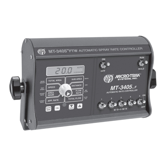
- Page 1 MT MT - - 3 3 4 4 0 0 5 5 FTW ™ AUTOMATIC SPRAY RATE CONTROLLER* *For sprayers equipped with a single flowmeter and three-way shut-off valves. R E F E R E N C E M A N U A L...
- Page 2 The MT-3405 FTW has been designed for easy installation and op er a tion. How ev er, since each in stal la tion will vary depending on your equipment, please take time to fa mil iar ize yourself with this manual and the actual components before beginning.
-
Page 3: Warranty
* Some limitations apply. See warranty statement for details. At Micro-Trak Systems, we believe a product that delivers quality and performance at a low cost is what is needed to help today’s operator and the operator of the future compete in the world mar ket. -
Page 4: Table Of Contents
Drive Shaft Speed Sensor Calibration, Min Flow ............................20 Flow Cal ............................................ 21 Exiting Calibration ........................................ 21 Care and Maintenance of your MT-3405 FTW ..............................21 Plumbing Overview Diagrams ..................................22-23 Fine Tuning Speed/Distance Calibration Value ............................. 24 Fine Tuning Flowmeter Calibration ..................................25 Test Speed............................................ -
Page 5: Table Of Contents
Electric Boom Valves, Servo Valve Control Signal, Servo Valve ......................31 Plumbing ..........................................31 Plumbing Troubleshooting Chart ..................................32 Flowmeter Cleaning and Assembly..................................33 MT-3405 FTW Wiring Diagram ..................................... 34 Plumbing Guidelines ..................................35-36 General, Pump Inlet, Agitation, Servo, Flowmeter, Pump ........................35 Valve Purpose and Adjustments ..................................36 Appendices .....................................37-44... -
Page 6: Basic Overview Of Typical Installation
MT-3405 FTW Basic Overview of Typ i cal Installation Hall-e ect Speed Sensor Magnets on Hub of Non-driven Wheel Remote Run/Hold MT-3405 FTW Console Harness Connection Battery Agitation Shot-o Valve * Main Harness Hitch Connectors Stainer * Trottle Valve *... -
Page 7: Component Parts And Assembly Hardware
Component Parts and Assembly Hardware Before beginning installation, check the carton contents for the following items: 5’ Hall-effect Flow Sensor Cable Console Mount Kit MT-3405 FTW Console with threaded sensor P/N 13774 P/N 13887 P/N 13096 MT - 3 4 0 5 FTW ™... - Page 8 Component Parts and Assembly Hardware (cont) 10’ Relief, White 10’ Speed, Blue Tie (Natural) Tie Booms 2&3 Harness Booms 4&5 Harness P/N 13762 P/N 13763 Speed Relief (Yellow Tie) Boom 4 (No Tie) Boom 3 (Yellow Tie) (Orange Tie ) Boom 2 Boom 5 (Red Tie)
-
Page 9: Introduction To The Mt-3405 Ftw
Electrical Installation Illustration 2 20-Amp In-line The MT-3405 FTW must be connected to a 12-volt DC elec- Fuse Required (WHITE) tri cal system. Power is connected directly to the battery. The MT-3405 FTW has an ON/OFF switch on the console to turn the power off when the system is not being used. -
Page 10: Speed Sensor Installation
(ATV’s), a minimum of two magnets Test magnet Illustration 3B are required. should alternately South The magnets provided by Micro-Trak are marked with attract and repel. North a dashed line on the SOUTH pole side of the magnet. North See Illustration 3A. -
Page 11: Attaching Magnets
MT-3405 FTW console every time a magnet 45° max passes by the tip of the speed sensor. For the speed sensor 3/8” nuts to operate properly, the spacing between the magnets and the tip of the sensor must always remain constant. -
Page 12: Speed Sensor Options
(cont) Speed Sensor Options In addition to the standard Hall-effect magnetic speed sensor, the MT-3405 FTW may be interfaced with a va ri ety of other speed sensing equipment. Several options are listed below. ASTRO SERIES OR OTHER GPS SPEED SENSOR INTERFACES... -
Page 13: Installing Flow Sensor Cable
Installation (cont) Installing Flow Sensor Cable With the flowmeter in place, install the flow sensor cable (GREEN body). Screw sensor all the way into hole of flow me ter. Tight en 3/8” jam nut to lock sen sor in place. Uncoil flow sensor cable and carefully route it to meet the main harness flow connector marked with GREEN tie. -
Page 14: Relief Valves
Installation (cont) Relief Valves The relief valve is used to “dump” pressure when all boom Illustration 10 valves are turned off. Whenever all the boom control switches are turned off, or when HOLD is selected with the master switch, the relief valve should be open. Use this plumbing illustration (See Illustration 10) as your pattern for proper installation if your relief valve has a flow-through port. -
Page 15: Remote Run/Hold
Installation (cont) Remote Run/Hold Illustration 13 BLACK TIE GREEN TIE GRAY TIE 3-PIN 3-PIN RED TIE FLOW M/P 150 M/P 150 TOWER SHROUD LOCAL ACCESS RUN/HOLD CONNECTOR GRAY TIE 3-PIN 3-PIN 3-PIN 3-PIN RUN/HOLD M/P 150 M/P 150 M/P 150 M/P 150 TOWER SHROUD... -
Page 16: Mt-3405 Ftw Console Functions
MT-3405 FTW Console Func tions The MT-3405 FTW features a large, easy-to-read liquid crystal display, lighted Brite-Knob rotary dial ™ and lighted panel for night use. TOTAL AREA: SUB AREA: Keeps a running count of the total acres Counts acres (hectares) worked. Can be used to (hectares) worked. -
Page 17: Calibration
Calibration English or Metric? The MT-3405 FTW is capable of displaying in for ma tion in Illustration 14 Amer i can En glish or standard Metric measurement. • To activate the English mode, turn power OFF and place the ro ta ry switch at “TOTAL AREA.” Hold down both the... -
Page 18: Entering Calibration Values
Calibration (cont) Entering Calibration Values BOOM SEL: To enter or change any of the system’s calibration values, This position is used to select the boom you must enter calibration mode. To enter calibration mode, section to be calibrated. With the ro ta ry switch in this posi- STOP the vehicle, place the run/hold switch on the front tion, the dis play will show panel in HOLD and press and hold the CAL button until “CAL”... -
Page 19: Banding Application Calibration, Circ
Calibration (cont) Entering Calibration Values (cont) Banding Application Calibration Illustration 17A In banding applications, you will still need to enter the total width of each boom section so that area counts correctly, but you must also calculate the percentage of your total width the band is covering and reduce your target rate to match. -
Page 20: Drive Shaft Speed Sensor Calibration, Min Flow
Calibration (cont) Entering Calibration Values (cont) Drive Shaft Speed Sensor Calibration When the display shows wheel circumference (“CAL” is displayed) , use the “+” or “-” key to adjust the displayed NOTE: If you have mounted the magnetic speed sen sor on value to any number be tween 10 and 15 (255mm to a wheel, skip this step and go on to Fine Tuning Speed/ 380mm). -
Page 21: Flow Cal
“FLOW CAL” value to make it operate properly number shown when “CAL” IS NOT displayed. with the MT-3405 FTW console. This number is stamped on The flowmeter calibration value is typical ly the metal tag attached to the flowmeter. See Illustration 20. -
Page 22: Plumbing Overview Diagrams
Calibration (cont) MT-3405 FTW Plumbing Overview Diagram... - Page 23 Calibration (cont) MT-3405 FTW Plumbing Diagram (cont) Illustration 20A Range Adjust Valve For Oversized Pumps Tee “C” Tee “A” Illustration 20B Pressure For Positive Displacement Pumps Relief Valve Tee “C” Tee “A” Illustration 20C If Optional Boost Valve Kit is Used...
-
Page 24: Fine Tuning Speed/Distance Calibration Value
Calibration (cont) Fine Tuning Speed/Distance Calibration Val ue This procedure is used to verify the calibration of the system. When the display shows distance (“CAL” is not In order to achieve accurate mea sure ments, each step in this displayed), ver i fy wheth er the number displayed is the fine tun ing procedure should be performed as pre cise ly as ex act dis tance you drove (with in “+”... -
Page 25: Fine Tuning Flowmeter Calibration
Pre-Field System Checkout starting on page 26. in performing pre-field checks. When a typical operating speed is entered, the MT-3405 FTW will respond as if you were actually driving that speed. It allows you to simulate your spraying application with plain water, while remaining... -
Page 26: Pre-Field System Checkout
Turn rotary switch to TEST SPEED position. Use the “+” MT-3405 FTW to perform at optimum level. Fill your sprayer or “-” button to enter minimum application speed. Do tank with clean water. -
Page 27: Operation
MANAUTO HOLD V 1 2 3 4 5 CONSOLE TOTAL AREA SUB AREA BOOM WIDTH SELECT The MT-3405 FTW control panel features a large, easy-to- TEST SPEED DISTANCE CIRC SPEED read backlit liquid crystal display, exclusive BriteKnob dial MT-3405 ™... -
Page 28: Test Speed
Operation (cont) Rotary Switches ROTARY SWITCH FLOW RATE During normal operation, you can view any one of eight Displays the actual gallons (liters) per minute being applied. monitored functions by turning the rotary switch to the TOTAL FLOW appropriate position. The functions that are active during Displays the total gallons (liters) applied since the counter normal operation are the blue boxes. -
Page 29: Troubleshooting
If you have a two-way radio, it may be mounted too close incorrectly or programmed incorrectly. Go back through to the console. Keep all MT-3405 FTW cables away from the the original procedures, make changes, and test for acre radio, its antenna and power cable. -
Page 30: Checking Individual Components
Troubleshooting (cont) Checking Individual Components CONSOLE RUN/HOLD JUMPER DUST COVER The only way to field test a console is to con nect it to a To test for proper continuity on the jumper wire, connect the harness on a vehicle with a known working console or install ohmmeter to the pins of the dust cover with the jumper wire it on an E-POP (Elec tron ic Point of Purchase) dis play stand. -
Page 31: Console Inputs
Troubleshooting ELECTRIC BOOM VALVES (cont) If the MT-3405 FTW is configured for 2-wire motorized ball Checking Console Inputs valve shut-offs (configuration connection removed), use an auto-polarity multimeter to test the boom valve wires. There If there is no response from any of the following tests, refer to should always be 12 volts present across the harness wires. -
Page 32: Plumbing Troubleshooting Chart
Troubleshooting (cont) Plumbing Troubleshooting Chart SYMPTOM POSSIBLE CAUSE POSSIBLE SOLUTION Loses pressure in • Pump Air-lock • Clean strainer MANUAL • Larger hoses Little or no pressure • Too much restriction in servo loop • Larger hoses and fittings adjustment in MANUAL •... -
Page 33: Flowmeter Cleaning And Assembly
Troubleshooting NOTE: The turbines have magnets built into the fins. There (cont) are no visible magnets. Flowmeter Cleaning and Assembly On a flat surface, place each housing half on end. Set and spin the turbine in each half. It should spin freely. If it does IMPORTANT: Opening the flowmeter will void the not spin freely, remove the turbine, wipe the shaft and try Flowmeter Calibration value assigned to your unit. -
Page 34: Mt-3405 Ftw Wiring Diagram
Troubleshooting (cont) MT-3405 FTW Wiring Diagram MT 3405 FTW Console 3-PIN M/P 10-PIN METRI-PACK TOWER 10-PIN METRI-PACK TOWER 630 SHROUD 10-PIN METRI-PACK SHROUD 10-PIN METRI-PACK SHROUD 10-PIN METRI-PACK SHROUD 10-PIN METRI-PACK TOWER 3-PIN M/P 630 TOWER 10-PIN METRI-PACK TOWER 10-PIN METRI-PACK TOWER... -
Page 35: Plumbing Guidelines
To determine MT-3405 FTW Sprayer Controller. This section will explain if your pump is large enough you must add up the gallons the purpose of each component, list some problems it can per minute of all three sections. -
Page 36: Valve Purpose And Adjustments
Plumbing Guidelines (cont) Valve Purpose and Adjustments TANK SHUT-OFF VALVE THROTTLE VALVE The tank shut-off valve is for convenience only. It allows The throttle valve limits your high end to maximize servo you to work on the plumbing without draining the tank. It performance. -
Page 37: Appendices
Appendices... -
Page 38: Appendix A: Optional Speed Sensor Mounting Installation
Appendix A Optional Speed Sensor Mounting Installation Implement Wheels Speed Sensor and Bracket Prepare and install magnet clips as shown. Place a magnet at the end of each clip (longest side of ¼” Bolts, magnet should point in the direction of wheel rotation). Lockwashers Place a cable tie (ribbed side toward magnet) around and Nuts... -
Page 39: Mounting On Drive Shaft
Hall-effect speed sen sor must alternate as tie as close to sensor assembly as possible. the shaft is turned. The magnets provided by Micro-Trak are NOTE: If you are using more than two magnets, please marked with a punched dashed line on the SOUTH pole side follow the directions on page 11. -
Page 40: Appendix B: Various Ball Valve Configurations
Appendix B Various Ball Valve Configurations Some basic 2, 3 & 4-wire configurations are shown at right. If you need assistance for wiring other than shown, contact Micro-Trak for wiring instructions. 2-Wire Valve Switching Wires* Valve 3-Wire Valve Micro-Trak Boom Connection (set for ball valve). -
Page 41: Appendix C: 12-Volt Servo Valve (Control Valve) Calibration
The MT-3405 FTW may operate sluggishly or be slow in control response time. For optimal performance, the control valve should be installed in a return line with a throttling... -
Page 42: Appendix D Adjusting By-Pass Valves
Appendix D Adjusting By-pass Valves The following is a basic procedure for adjusting the by-pass valves in a single flowmeter, three-way boom shut-off valve system. You may need to check your sprayer’s operating manual for more specific details. NOTE: This procedure is not intended to replace any sprayer manufacturer’s instructions. -
Page 43: Appendix E: Conversion Chart
Appendix E Conversion Chart English to Metric Metric to English When You Know Multiple By To Find When You Know Multiple By To Find LINEAR MEASUREMENT LINEAR MEASUREMENT inches 25.4 millimeters millimeters .039 inches feet 0.305 meters meters 3.28 feet yards 0.914 meters... -
Page 44: Appendix F Replacement Parts List
Appendix F Replacement Parts List The following replacement parts are available from your dealer or distributor, or directly from: Micro-Trak Systems, Inc. P.O. Box 99, 111 East LeRay Avenue Eagle Lake, MN 56024-0099 When ordering parts, please list the model number of your console, and the description and part number of each part that you want to order. -
Page 45: Notes
NOTES... - Page 46 NOTES...
- Page 48 1305 Stadium Road, Mankato, MN 56001-5355 Toll Free: (800) 328-9613 Phone: (507) 257-3600 www.micro-trak.com • trakmail@micro-trak.com P/N 13895 Rev. 1 • © 2000 Micro-Trak Systems, Inc. • Printed in U.S.A.
Need help?
Do you have a question about the MT-3405 FTW and is the answer not in the manual?
Questions and answers