
Related Manuals for micro-trak MT-2405FTW II


Summary of Contents for micro-trak MT-2405FTW II
- Page 1 MT-2405FTW 5 - B O O M A U T O M A T I C R A T E C O N T R O L R E F E R E N C E M A N U A L M A N U F A C T U R E D I N U .
- Page 2 The MT-2405FTW II has been designed for easy installation and op er a tion. How ev er, since each in stal la tion will vary depending on your equipment, please take time to fa mil iar ize yourself with this manual and the actual components before beginning.
-
Page 3: Micro-Trak Warranty
* Some limitations apply. See warranty statement for details. At Micro-Trak Systems, we believe a product that delivers quality and performance at a low cost is what is needed to help today’s operator and the operator of the future compete in the world mar ket. -
Page 4: Table Of Contents
Micro-Trak Warranty .....................................3 Table of Contents ....................................4 Component Parts and Assembly ..............................5-6 Basic Overview of Installation ................................7 MT-2405FTW II System Layout ................................8 MT-2405FTW II Wiring Diagram .................................9 Installation ......................................10-17 Required Tools ........................................10 Mounting the Display Console ..................................10 Electrical Installation .....................................11-12... -
Page 5: Component Parts And Assembly
R E F E R E N C E M A N U A L M A N U F A C T U R E D I N U . S . A . B Y : MT-2405FTW II Console Owner’s Manual 10’... - Page 6 Component Parts and Assembly Hardware (cont) Power (no tie) Servo Booms 1-5 and (no tie) Boom Enalbe (no tie) Relief Valve Relay Connection Speed Flow (yellow tie) (green tie) Run/Hold (gray tie)
-
Page 7: Basic Overview Of Installation
Basic Overview of Typ i cal Installation Hall-E ect Speed Sensor (or Vansco or Optional Radar or GPS Speed Sensor) Magnets on Hub of Non-driven Wheel Local Access MT-2405FTW II Console Speed Connection Battery Main Harness Hitch Connection Rear Speed Connection... -
Page 8: Mt-2405Ftw Ii System Layout
MT-2405FTW II System Layout... -
Page 9: Mt-2405Ftw Ii Wiring Diagram
MT-2405FTW II Wiring Diagram Universal Switch Box Harness MT-2405F II Console 10-PIN MERTI-PACK SHROUD 10-PIN MERTI-PACK TOWER 10-PIN MERTI-PACK TOWER 10-PIN MERTI-PACK SHROUD FLOW RUN/HOLD SPEED SERVO POWER... -
Page 10: Installation
Installation Tools Needed to Install MT-2405FTW II Mounting the Display Console • Screwdrivers • Pliers • Set of Wrenches • Wire Cutter • Electric Drill and Bits • Hammer Select a mounting location which seems most workable, • 12-Volt Test Light •... -
Page 11: Electrical Installation
In routing cable to con sole, avoid ar eas where The MT-2405FTW II must be connected to a 12-volt DC the ca ble may be sub ject ed to abra sion or ex ces sive heat. - Page 12 ON (open), and ground when the valve is OFF (closed). Connect the boom detect wires from the MT-2405FTW II harness to the wires on the shut-off valve harness that are on NOTE: Always turn power to the switches OFF before the solenoid side of the boom switches.
-
Page 13: Speed Sensor Installation
See the following tables to find the minimum number of magnets required (always an even number) - South North The magnets provided by Micro-Trak are marked with a punched dashed line on the SOUTH pole side of the magnet. Illustration 6C 1” Minimum See Illustration 6A. -
Page 14: Attaching The Speed Sensor
45° max is sent to the MT-2405FTW II console every time a magnet passes by the tip of the speed sensor. For the speed sensor 3/8” nuts to operate properly, the spacing between the magnets and the tip of the sensor must always remain constant. -
Page 15: Mounting And Plumbing Flowmeter
Installation (cont) Illustration 8 Mounting and Plumbing Flowmeter Hose Clamps* Sprayer Line* ¾” NPT Male Fitting* The Flowmeter must be installed in the main boom line after any strainers, return lines, or valves. Se cure ly mount flow me- Flowmeter Hose Clamps* ter (hardware not supplied) in a vertical position in an area Sensor... -
Page 16: Manual Pressure Relief Valve
If more length is required, use a 3-pin W/P extension cable of the appropriate length. Servo IMPORTANT NOTE: If using the MT-2405FTW II with an old -style Micro-Trak servo valve, the valve voltage must be set to 8 volts. -
Page 17: Remote Run/Hold
Installation the face of the magnet that is toward the sensor when (cont) the console does not indicate “HOLD.” Install the magnet Remote Run/Hold with the marked side facing the sensor. When the mag- net is away from the sen sor, the con sole will be in HOLD The run/hold sensor cable has a BLACK body and a GRAY tie and the area and distance counting functions will be near the 3-pin M/P connector and mates with the main har-... -
Page 18: Care And Maintenance
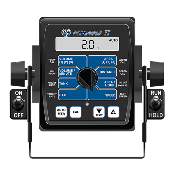
MT-2405FTW II Console Func tions The MT-2405FTW II features a large, easy-to-read liquid crystal display and lighted panel for night use. When the console is turned on, it will display the number of hours of operation for two seconds, then 3-Way for two seconds, then the software version along with the “V”... -
Page 19: Calibration
Illustration 14 English or Metric MT-2405F II ™ ™ The MT-2405FTW II is capable of displaying in for ma tion in MANAUTO Amer i can En glish or standard Metric measurement. The CALHOLD 1 2 3 4 5 MT-2405FTW II is shipped from the factory programmed for English. - Page 20 Calibration (cont) Entering Calibration Values (cont) TARGET RATE: INLINE/BYPASS: Enter the value for the desired target The display will show InLinE or bYPASS. application rate in gallons per acre (liters per Use the “+” or “-” buttons to toggle to desired selection. Inline hectare).
-
Page 21: Radar/Gps Speed Sensor Calibration
Calibration (cont) Entering Calibration Values Illustration 16 (cont) SPEED CAL: This position is used to calibrate the speed MT-2405F II ™ s e n s o r for ac cu rate speed and dis tance measurement. MANAUTO When this position is MANAUTO CALHOLD CALHOLD... -
Page 22: Exiting Calibration
Test speed is a built-in ground speed simulator for ac cu rate liquid mea sure ment. that is used in performing pre-field checks. When a typical operating speed is entered, the MT-2405FTW II will respond Every flowmeter as if you were actually driving that speed. -
Page 23: "Special" Calibration
“Special” Calibration The “Special” Calibration mode is used to set up system “Special” Calibration parameter(s) can then be accessed with parameters that rarely need to be changed or adjusted. To the rotary switch per the illustration below. To exit “Special” enter “Special”... - Page 24 FLOW MINUTE NOTE: If using an old style and the word “FILL” flashes Micro-Trak servo valve, (see on the display. Range is illustration), set to 8 volts. OFF or 1-65,535. When the tank value drops below the set point, the alarms will notify the user that the tank level is low.
-
Page 25: Pre-Field System Checkout
20% higher MT-2405FTW II to perform at optimum level. Fill your sprayer than the desired application rate. tank with clean water. DO NOT use chemicals until the entire sys tem is completely checked out and operating properly. -
Page 26: In-Line
Adjust agitation valve for desired agitation. If range valve is MT-2405FTW II to perform at optimum level. Fill your sprayer installed, adjust range valve until display reads 10% higher tank with clean water. -
Page 27: Functions
Field System Checkout described on pages 25-26 prior to MANAUTO beginning any field operations. CALHOLD The MT-2405FTW II system can be operated in either Manual or 1 2 3 4 5 Automatic mode. In manual mode, the application rate (GPA VOLUME... -
Page 28: Operation
Operation (cont) Console Buttons and Switches Rotary Switch Positions (cont) During normal operation, you can view any one of eight ON-THE-GO “DELTA” RATE ADJUSTMENTS monitored functions by turning the rotary switch to the The calibrated target rate in gallons (liters) per acre represents appropriate position. -
Page 29: Resetting System Counters
Operation (cont) MT-2405F II ™ Resetting System Counters AUTO The AREA, DISTANCE and VOLUME counters maintain a 1 2 3 4 5 running count during operation regardless of the position of the rotary switch. When any of these counters reach VOLUME AREA FLOW... -
Page 30: Clearing System Counters
Operation (cont) Clearing System Counters When the desired counter number is displayed, press the “-” (RESET) button and “CLEAr” will be displayed. NOTE: Holding the “-” (RESET) button for 2 seconds will clear both the #3 AREA counter AND the #3 VOLUME counter whether the rotary switch is in the AREA or the VOLUME position. -
Page 31: Troubleshooting
Troubleshooting Messages and Warnings Typically indicates that defaults were entered by powering up with the CAL and “-” buttons held, but calibration mode was not entered and exited. Cycling power will not clear the bad CAL message, it can only cleared by entering and exiting calibration mode. -
Page 32: General
If you have a two-way radio, it may be mounted too close to magnet assembly. Make sure magnet polarities are alternated. the console. Keep all MT-2405FTW II cables away from the Also check cable for breaks or incomplete connection. For radio, its antenna and power cable. -
Page 33: Checking Individual Components
Troubleshooting (cont) Checking Individual Components CONSOLE MAGNETIC HALL-EFFECT SPEED AND FLOW The only way to field test a console is to con nect it to a SENSORS harness on a vehicle with a known working console or install CAUTION: Improper connection or voltage could damage it on an E-POP (Elec tron ic Point of Purchase) dis play stand. -
Page 34: Console Inputs
Proper plumbing is a very important factor in obtaining optimal performance from your MT-2405FTW II system. The Check for 12 volts between pins B (white) and C (black) chart on the next page will help you determine what area of of the main harness remote run/hold cable (grey tie). -
Page 35: Plumbing Troubleshooting Chart
Troubleshooting (cont) Plumbing Troubleshooting Chart SYMPTOM POSSIBLE CAUSE POSSIBLE SOLUTION Loses pressure in • Pump Air-lock • Clean strainer MANUAL • Larger hoses Little or no pressure • Too much restriction in servo loop • Larger hoses and fittings adjustment in MANUAL •... -
Page 36: Plumbing Guidelines
Plumbing Guidelines General PUMP In order for your sprayer to function properly, it must be correctly plumbed. The system diagrams (See pages 8 and 9) The pump must have enough capacity to satisfy the agitation, show the plumbing configuration that works best with the servo and flowmeter sections of the plumbing. - Page 37 Plumbing Guidelines (cont) Valve Purpose and Adjustments TANK SHUT-OFF VALVE THROTTLE VALVE The tank shut-off valve is for convenience only. It allows you The throttle valve limits your high end to maximize servo performance. Start with throttle valve fully open and perform to work on the plumbing without draining the tank.
-
Page 38: Flowmeter Assemblies
Flowmeter Assembly IMPORTANT: Opening the flowmeter will void the Flowmeter On a flat surface, place each housing half on end. Set and Calibration value assigned to your unit. However, you may spin the turbine in each half. It should spin freely. If it does need to take the flowmeter apart for periodic cleaning or not spin freely, remove the turbine, wipe the shaft and try to remove an obstruction. -
Page 39: Appendices
Appendices... -
Page 40: Appendix A: Boom Shut-Off Relay Kit
Appendix A Boom Shut-off Relay Kit for Universal Switch Box Harness (P/N 01559) If your sprayer is equipped with electric solenoid valves, the Be sure power to the switch box is disconnected. Cut systems’ remote Run/Hold sensor may be used to control the positive wire of the solenoid control switch box. -
Page 41: Appendix B: Optional Speed Sensor Mounting Installation
Appendix B Optional Speed Sensor Mounting Installation Implement Wheels Speed Sensor and Bracket Secure magnets mechanically or with epoxy. Rigidly mount sensor mounting bracket to the wheel ¼” Bolts, assembly. Cut or bend “L” bracket as required for proper Lockwashers and Nuts positioning of sensor. - Page 42 Hall-effect speed sen sor must alternate as from magnets (1/4” to 1/2”, or 6mm to 13mm). When the shaft is turned. The magnets provided by Micro-Trak are distance is set, tight en nuts to lock sensor in place.
-
Page 43: Appendix C: Fine Tuning Speed/Distance Calibration Value Without Run/Hold Switch
Appendix C Fine Tuning Speed/Distance Calibration Value without Run/Hold Switch This procedure is used to verify the calibration of systems When the display shows distance (“CAL” is flashing), ver- WITHOUT run/hold switch installed. In order to achieve i fy wheth er the number displayed is the ex act dis tance accurate measurements, each step in this fine tuning you drove (with in + or - 1 - 2 %). -
Page 44: Appendix D: Fine Tuning Speed/Distance Calibration Value With Run/Hold Switch
Appendix D Fine Tuning Speed/Distance Calibration Value with Run/Hold Switch This procedure is used to verify the calibration of systems With the rotary dial still at DISTANCE (SPEED CAL), press WITH a Run/Hold Switch or an optional remote run/hold kit and hold the “CAL”... -
Page 45: Appendix E: Fine Tuning Flowmeter Calibration Value
Appendix E Fine Tuning Flowmeter Calibration Value This procedure is used to verify and fine-tune the flowmeter Momentarily press the CAL button. The word CAL will be calibration. Every flowmeter is calibrated with water at the on steadily and the flowmeter calibration number will be factory and stamped with a calibration val ue. -
Page 46: Appendix F: Various Ball Valve Configurations
Appendix F Various Ball Valve Configurations Some basic 2, 3 & 4-wire configurations are shown below. If you need assistance for wiring other than shown, contact Micro-Trak for wiring instructions. 12-volts Valve Switching Wire Ground Switching Wire Relay + Relay –... -
Page 47: Appendix G Adjusting By-Pass Valves
Appendix G Adjusting By-Pass Valves The following is a basic procedure for adjusting the by-pass valves in a single flowmeter, three-way boom shut-off valve system. You may need to check your sprayer’s operating manual for more specific details. NOTE: This procedure is not intended to replace any sprayer manufacturer’s instructions. -
Page 48: Appendix H: Radar Adapter Cables
Appendix H Radar Adapter Cables In-Cab John Deere Metri-Pack Connector RADAR CONNECTOR SIGNAL PIN 8000/9000 Series DICKEY-john Ground Signal Common Cannon DICKEY-john Deutsch DICKEY-john P/N 14810 DICKEY-john Ford Packard DICKEY-john In-Cab JD (8000 & 9000’s Metri-Pack Magnavox & Phillips Packard DICKEY-john Radar Amp Connector Conxall Raven... -
Page 49: Appendix I Conversion Chart
Appendix I Conversion Chart English to Metric Metric to English When You Know Multiple By To Find When You Know Multiple By To Find LINEAR MEASUREMENT LINEAR MEASUREMENT inches 25.4 millimeters millimeters .039 inches feet 0.305 meters meters 3.28 feet yards 0.914 meters... -
Page 50: Appendix J: Replacement Parts
Run/hold, speed, flow harness 13824 Terminal Block Kit 01559 Relay Kit (for Auto Boom Shutoff) 14360 MT-2405FTW II Power (On/Off) Switch Kit OPTIONAL 2-PIN, 3-PIN, AND 10-PIN METRI-PACK 150 EXTENSION CABLES: Part No. M/P 2-Pin Part No. M/P 3-Pin Part No. - Page 52 M A N U F A C T U R E D I N U . S . A . B Y : 1305 Stadium Road, Mankato, MN 56001-5355 Toll Free: (800) 328-9613 or (507) 257-3600 www.micro-trak.com • trakmail@micro-trak.com © 2005 Micro-Trak Systems, Inc. Printed in U.S.A. P/N 17005 Rev. 2...
Need help?
Do you have a question about the MT-2405FTW II and is the answer not in the manual?
Questions and answers