Table of Contents
Advertisement
Quick Links
Advertisement
Table of Contents

Related Manuals for micro-trak DrillMaster


Summary of Contents for micro-trak DrillMaster
- Page 1 System Manual...
- Page 2 The DrillMaster is designed to drive a Proportional Flow Control Valve using a PWM output. The Valve controls the flow in 1 to 3 Hydraulic Motors so it can be used with 1 to 3 Section Grain Drills or Fertilizer Applicators. All Motors are in series so they all rotate at the same speed and apply the same amount of Seed or Fertilizer.
-
Page 3: Micro-Trak Warranty
Eagle Lake, MN 56024-0099 At Micro-Trak® Systems, we believe a product that delivers quality and performance at a reasonable cost is what is needed to help today’s operator and the operator of the future compete in the world mar ket. -
Page 4: Table Of Contents
Micro-Trak Warranty .....................................3 Table of Contents ....................................4 Component Parts and Assembly Hardware .............................5 DrillMaster System Layout - Mounted Single Section ........................6 DrillMaster Wiring Diagram - Mounted Single Section .........................7 DrillMaster System Layout - Drawn Multi Section ..........................8 DrillMaster Wiring Diagram - Drawn Multi Section ........................9 DrillMaster Seed Rate Controllers ..............................10... -
Page 5: Component Parts And Assembly Hardware
Component Parts and Assembly Hardware Before beginning installation, check the carton contents for the following items: System Manual DrillMaster Console System Manual Console Mount Kit P/N 17899 P/N 50318 P/N 13181 Power Cable 14” Nylon cable ties (10) Run/Hold Switch... -
Page 6: Drillmaster System Layout Mounted Single Section
DrillMaster System Layout Mounted Single Section... -
Page 7: Drillmaster Wiring Diagram Mounted Single Section
DrillMaster Wiring Diagram Mounted Single Section DRILL MASTER CONSOLE... -
Page 8: Drillmaster System Layout Drawn Multi Section
DrillMaster System Layout Drawn Multi Section... -
Page 9: Drillmaster Wiring Diagram Drawn Multi Section
DrillMaster Wiring Diagram Drawn Multi Section 18 GA. RED 18 GA. WHT 18 GA. BLK 18 GA. RED 10-PIN 10-PIN 18 GA. WHT 18 GA. BLK SHROUD TOWER 18 GA. RED 18 GA. BLK... -
Page 10: Drillmaster Seed Rate Controllers
DrillMaster Seed Rate Controllers Single Drive Closed Center Single Drive Open Center FLOW SENSOR RETURN FLOW SENSOR PWM VALVE POPPET VALVE POPPETVALVE RETURN PRESSURE PWM VALVE PRESSURE Multi-Drive Closed Center RIGHT FLOW SENSOR CENTER POPPET VALVE RIGHT POPET VALVE RETURN... -
Page 11: Installation
Installation Illustration 1A Mounting the Display Console Select a mounting location which seems most workable, Bolts and that best fits your needs. It should be con ve nient to Drill ¼” (7mm) reach and high ly vis i ble to the op er a tor. DO NOT IN STALL holes for bolts, IN A POSITION THAT OB STRUCTS THE VIEW OF THE ROAD or 3/16“... -
Page 12: Electrical Installation
Speed Sensor Options In addition to the standard Hall-effect magnetic speed sensor, the DrillMaster may be interfaced with a va ri ety of other speed sensing equipment. Several options are listed below. Astro 5 or other GPS Speed Sensor Interface... -
Page 13: Remote Run/Hold
HOLD and the area and distance counting functions will be disabled. DrillMaster Care and Maintenance Store the console in a cool dry location if it will not be used for an extended period of time, such as during the off-season. As with any electronic equipment, use care in cleaning so that water or other... -
Page 14: Drillmaster Console Functions
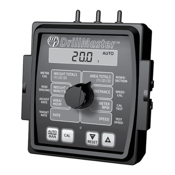
DrillMaster Console Func tions The DrillMaster features a large, easy-to-read liquid crystal display, easy-to-use rotary dial and lighted panel for night use. SECTION ON/OFF: The Console has three Section ON/OFF toggle switches on top of the Console. The toggle switches turn Drill Sections on and off directly and also signal the Console which Sections are on or off. -
Page 15: Calibration
Selecting Measurement Units English, Metric or Turf? Illustration 5 The DrillMaster is capable of displaying in for ma tion in Amer i can DrillMaster En glish or standard Metric measurement. The DrillMaster is shipped from the factory programmed for English. -
Page 16: Entering Calibration Values
Instead only a small sample from one Row is needed (1) (2) (3) SECTION DrillMaster can have and it can be performed in the field. But it can also test up to three Sections. The total width of multiple Rows at once if desired. -
Page 17: Factory-Loaded Calibration Values
WARN LED will turn off and it will exit Test Speed and CAL Mode. The Test Speed cannot be turned off by reducing it to zero because the minimum Test Speed is 0.1 mph. DrillMaster Factory-Loaded Calibration Values Default Values... -
Page 18: Speed Cal For Radar Or Gps
Calibration (cont) Speed Cal for Radar or GPS Speed Sensors See the table below for SPEED CAL numbers to enter for various radar models or GPS speed sensors. To fine tune the SPEED CAL number, see Appendix B. Radar or GPS Speed Sensor Calibration English Metric Radars... -
Page 19: Special" Calibration
1 of Special Cal is selected. To select page 2 of Special Cal, momentarily NOTE: You must exit “Special” Calibration to save changes. Special Cal Special Cal PWM Version DrillMaster CALHOLD Page 1 Page 1 Page 2 WEIGHT TOTALS... -
Page 20: Entering "Special" Calibration Values
“Special” Calibration (cont) Entering Page 1 “Special” Calibration Values UNITS: AUTO SHUTOFF ON/OFF: Chooses the system of units desired. Turf units are Area/Hour allows the user to the same as English turn the Auto Shut Off feature On or Off by using the “+”/”-” AREA TOTALS units except Area is in (RESET) keys and the display will show On or Off. -
Page 21: Entering "Special" Calibration Values
“Special” Calibration (cont) Entering Page 2 “Special” Calibration Values PWM FREQUENCY: It can be adjusted from 50 Hz to 500 Hz in 1.0 Hz steps. It should be set to the optimum frequency for the particular valve AREA TOTALS ROWS/ being used. -
Page 22: Operation
Run/Hold switch is in the RUN position, pressing the “+” or “-” buttons will increase or decrease the application NOTE: The DrillMaster system can be operated in either rate via the control valve. Manual (MAN) or Automatic (AUTO) mode. The following contains additional information. -
Page 23: Console Switches And Inputs
Operation (cont) Console Switches and Inputs SECTION ON/OFF BIN LEVEL SENSOR INPUT The Console has three Section On/Off toggle switches on top When the Bin Level Sensor input goes low, the Seed Bin of the Console. The toggle switches turn Drill Sections ON is near empty and the Console will begin to flash "FILL"... -
Page 24: General Information
Operation (cont) General Information WARNING DEVICE WEIGHT/MINUTE The console is equipped with a RED warning light. In AUTO, Displays the pounds (kg) per minute being applied. the light will flash when the actual application is plus or minus WEIGHT TOTALS (1) (2) (3) 10 percent of the calibrated target rate. -
Page 25: Resetting System Counters
Operation (cont) DrillMaster Resetting System Counters MANAUTO The AREA, DISTANCE and WEIGHT totals counters maintain CALHOLD V 1 2 3 4 a running count during operation regardless of the position of the rotary switch. When any of these counters reach... -
Page 26: Clearing System Counters
“Pre-field” procedure to ensure that your settings, oil flow CONSOLE and desired speed range will allow the DrillMaster to provide Turn rotary switch to TEST SPEED position. Use the “+” or “-” the required application control. This procedure should be button to enter minimum application speed. -
Page 27: Troubleshooting
Troubleshooting Messages / Warnings Typically indicates that defaults were entered by powering up with the CAL and “-” buttons held, but calibration mode was not entered and exited. Cycling power will not clear the bad CAL message, it can only cleared by entering and exiting calibration mode. -
Page 28: General
If you have a two-way radio, it may be mounted too close to For easy-to-follow guidelines, refer to the troubleshooting the console. Keep all DrillMaster cables away from the radio, section which follows. its antenna and power cable. -
Page 29: Checking Individual Components
Troubleshooting (cont) Checking Individual Components CONSOLE MAGNETIC HALL-EFFECT SPEED AND FLOW SENSORS The only way to field test a console is to con nect it to a CAUTION: Improper connection or voltage could damage the Halleffect sensor. harness on a vehicle with a known working console or install it on an E-POP (Elec tron ic Point of Purchase) dis play stand. -
Page 30: Checking Console Inputs
Troubleshooting PWM VALVE CONTROL SIGNAL (cont) With the console turned ON, put the console in MANUAL Checking Console Inputs mode, place the remote Run/Hold switch in the RUN position and turn at least one boom switch to ON. Using a voltmeter CONSOLE INPUTS or simple test light, connect the positive lead from the If there is no response from any of the following tests, refer... -
Page 31: Appendices
Appendices... -
Page 32: Appendix A: Fine Tuning Speed/Distance Calibration Value With Run/Hold Switch Kit Installed
Run/Hold switch to start and stop DrillMaster the counting function. It is not recommended to start from a dead stop at the starting flag and stop at the ending flag. -
Page 33: Appendix B: Cal Test Fine Tuning Calibration Values
Appendix B Cal Test Fine Tuning Calibration Values For maximum accuracy the user must follow the steps below. this time the Weight displayed in the CAL TEST (METER RPM) position will count up to something close to the Before starting the test make sure all cal factors including Sample Size (instead of displaying RPM). -
Page 34: Appendix C: Meter Cal Fine Tuning Calibration Values
Appendix C Meter Cal Fine Tuning Calibration Values Start Calibrate. (While in Hold, press CAL key for 1 sec). Back the applicator up to a material pile for unloading or lay out a tarp to catch the seed or place a container under Select the METER CAL position and the current METER each Row. -
Page 35: Appendix D: Bin Level Sensor Kit Installation
Appendix D Bin Level Sensor Kit Installation INSTALLATION ELECTRICAL INSTALLATION Mount the bin level sensor(s) at the desired level in the Insert the pins into the provided connector housing per the bin(s). The connector body is supplied loose so a smaller diagram below. -
Page 36: Appendix E Radar Adapter Cables
Appendix E Radar Adapter Cables In-Cab John Deere Metri-Pack Connector RADAR CONNECTOR SIGNAL PIN 8000/9000 Series DICKEY-john Ground Signal Common DICKEY-john Cannon Deutsch DICKEY-john P/N 14810 DICKEY-john Ford Packard DICKEY-john In-Cab JD (8000 & 9000’s Metri-Pack Magnavox & Phillips Packard DICKEY-john Radar Amp Connector Conxall Raven... -
Page 37: Appendix F: Conversion Chart
Appendix F Conversion Chart English to Metric Metric to English When You Know Multiple By To Find When You Know Multiple By To Find LINEAR MEASUREMENT LINEAR MEASUREMENT inches 25.4 millimeters millimeters .039 inches feet 0.305 meters meters 3.28 feet yards 0.914 meters... -
Page 38: Appendix G Replacement Parts List
Console mount kit* 13226 5-foot remote run/hold sensor cable 14315 Power cable 17881 Cable, DrillMaster Section 1 & 3 - Multi Section 17882 Cable, DrillMaster Section 2 - Multi Section 17883 Cable, DrillMaster PWM and R/H - Multi Section 17884... - Page 40 Manufactured in U.S. A. by 111 East LeRay Ave., Box 99, Eagle Lake, MN 56024-0099 Toll-Free: 800-328-9613 507-257-3600 • Fax 507-257-3001 www.micro-trak.com • trakmail@micro-trak.com Printed in U.S.A. Copyright © 2019 Micro-Trak® Systems, Inc. • P/N 50318 • 021919...
Need help?
Do you have a question about the DrillMaster and is the answer not in the manual?
Questions and answers