Table of Contents
Advertisement
Quick Links
Advertisement
Table of Contents
Troubleshooting

Subscribe to Our Youtube Channel
Related Manuals for micro-trak AgriCruise II


Summary of Contents for micro-trak AgriCruise II
- Page 1 uise Utility Vehicle Ground Speed Control Reference Manual...
- Page 2 If you do encounter a problem that cannot be corrected by reviewing this manual, consult your dealer or distributor, or contact a Micro-Trak technician for assistance. Toll Free in U.S. or Canada: (800) 328-9613 or (507) 257-3600 E-mail: trakmail@micro-trak.com...
-
Page 3: Micro-Trak Warranty
* Some limitations apply. See warranty statement for details. At Micro-Trak Systems, we believe a product that delivers quality and performance at a low cost is what is needed to help today’s operator and the operator of the future compete in the world mar ket. -
Page 4: Table Of Contents
Table of Contents Micro-Trak Warranty ............................3 Table of Contents .............................. 4 Component Parts and Assembly Hardware ....................5 Agri-Cruise II System Overview ........................6 Agri-Cruise II Wiring Diagram ........................7 Installation ..............................8-17 Mounting the Display Console ...........................8 Actuator Installation ..............................8-11 Mounting Actuator ..............................8... -
Page 5: Component Parts And Assembly Hardware
Component Parts and Assembly Hardware Before beginning installation, check the carton contents for the following items: uise Utility Vehicle Ground Speed Control uise Fuse P/N 12682 AREA/ AREA WIDTH GAIN HOUR APPL. SPEED DAMP’G DISTANCE 1 TIME TARGET SLEW DISTANCE 2 TIME TARGET TARGET... -
Page 6: Agri-Cruise Ii Tm Wiring Diagram
AgriCruise II System Overview... - Page 7 AgriCruise II Wiring Diagram...
-
Page 8: Installation
Installation Put rubber washers on carriage bolts and put the bolts Mounting the Display Console through the bracket holes from the inside out. Loosely attach the mount knobs onto the bolts. Place the console over the Select a mounting location which seems most workable, carriage bolt heads and tighten knobs to se cure the console. -
Page 9: Anchoring Cruise Cable
Installation (cont) Actuator Installation (cont) Anchoring Cruise Cable There are two (2) types of connectors used to anchor the Cruise Cable. Illustration 2A • Snap-In Adapter • Flag Nut 11 mm BOX Snap-In Adapter LOCKWASHER NUT END WRENCH To use the Snap-In Adapter, it will be necessary to form threads on the end of the Cruise Cable. - Page 10 Installation (cont) Actuator Installation (cont) Anchoring Cruise Cable (cont) Illustration 2E Flag Nut LOCKWASHER NUT To use the Flag Nut, it will be necessary to form threads on the end of the Cruise Cable. This is easily accomplished by placing the Lockwasher Nut on the end of the Cruise Cable with your fingers.
-
Page 11: Attaching Cruise Control To Throttle
Installation (cont) Throttle Connections Actuator Installation BEAD CHAIN (cont) THREE BEAD BEAD CHAIN BEAD CHAIN CONNECTOR CONNECTOR Attaching Cruise Cable to Throttle NOTE: This section will cover some of the proper ways to use the hardware available. Each method contains sample EYELET illustrations showing how the connector is used in an actual CONNECTOR... -
Page 12: Electrical Installation
Installation (cont) Illustration 3D Actuator Installation TUBE CLAMP (cont) THROTTLE M5 BOLT CABLE Attaching Cruise Cable to Throttle (cont) Tube Clamp and Eyelet Connector EYELET Select a Tube Clamp that fits the throttle cable. Make sure CONNECTOR CRUISE the tabs of the Tube Clamp point away from the carburetor CABLE LOCKNUT or air throttle, this will prevent the throttle from hanging. -
Page 13: Magnetic Speed Sensor Installation
Please read the following information about magnet spacing hub or drive shaft. and polarity. The magnets provided by Micro-Trak are marked with a The number of magnets that must be used depends on the dashed line on the SOUTH pole side of the magnet. -
Page 14: Magnet Installation
Installation (cont) Magnet Installation (cont) Example: Installing four magnets with adhesive. Perform the following steps to ensure proper magnet installation. It is recommended that the magnets be installed on the Put a generous amount of glue at each of the marks, on largest diameter portion of the axle or hub. -
Page 15: Speed Sensor Bracket Installation
Installation (cont) Speed Sensor Bracket Installation NOTE: The Speed Sensor must be attached to the vehicle SPEED SIGNAL so that it will maintain its position with respect to the PICK-UP magnets. If the magnets move the sensor must move with them to avoid dislodging the magnets or damaging the speed sensor. -
Page 16: Connecting The Speed Sensor Cable
It features state-of-the-art electronic design/ manufacturing, rugged aluminum housing and complete Vansco Radar Speed Sensor testing and certification. Contact a Micro-Trak dealer/distributor for de tails on any of these products, or call Mi cro-Trak Systems, Inc. at 1-800-328-9613. -
Page 17: Brake Sensor Mounting And Adjustment
Installation (cont) Brake Sensor Mounting and Adjustment When installed properly, the brake sensor will cancel BRAKE SENSOR automatic control when the brakes are activated. Locate the BRAKE PEDAL pivot bolt. Actuate the brake pedal and locate a portion of the brake assembly that moves ¾ of an inch from the “at rest”... -
Page 18: Optional Shaft Rpm
• P/N 10013 Mounting Bracket Mount magnet with SOUTH pole facing the tip of the sensor. The magnets provided by Micro-Trak are marked with a dashed line on the SOUTH pole side of the magnet. See Illustration 6. Some installations may require more Illustration 7 than one magnet per shaft. -
Page 19: Agri-Cruise Ii Tm Console Functions
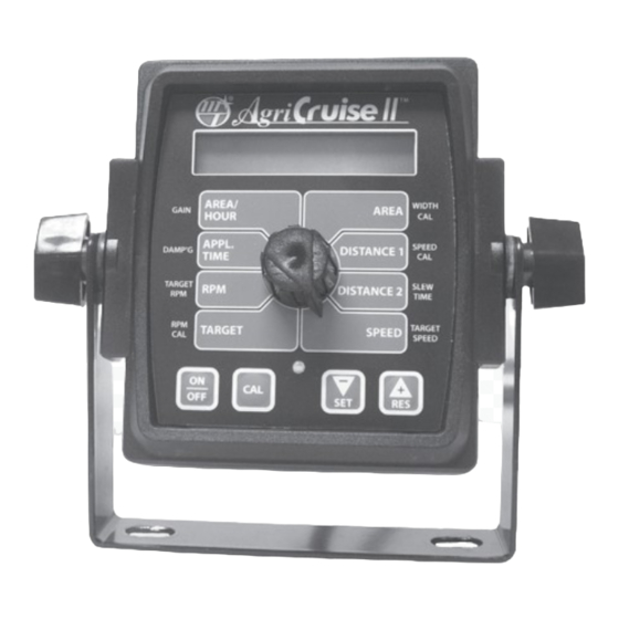
Agri-Cruise II Console Func tions The Agri-Cruise II features a large, easy-to-read liquid crystal display, easy-to-use rotary dial and lighted display. AREA/HOUR: AREA: Displays the current Area/Hour (10 s) in Displays area in acres, hectares or turfs (1000 ft based on the selected units and shows the area covered acres/hour, 1000 ft /hour or hectares/hour, depending on since the last time the counter was reset . -
Page 20: Selecting Measurement Units
Selecting Measurement Units Illustration 9 English, Metric or Turf? uise The Agri-Cruise II is capable of displaying in for ma tion in Amer i can En glish or standard Metric or Turf measurement units. The Agri-Cruise II is shipped from the factory programmed for English. -
Page 21: Special" Calibration
“Special” Calibration NOTE: Changing UNITS will load defaults, so units should To exit Special Calibration, press and hold the CAL button always be selected first and then all other SPECIAL for one (1) second. The console will store any changes and CALIBRATE factors may be applied. -
Page 22: Entering Calibration Values
“Special” Calibration (cont.) Entering “Special” Calibration Values NOTE: Changing UNITS will load defaults, so units should RPM Lower Limit: Allows the user to adjust the lower always be selected first and then all other SPECIAL limit for RPM automatic control between 100 and 1500 CALIBRATE factors may be applied. -
Page 23: Calibration
Calibration Entering Calibration Values RPM CAL: To enter or change any of the system’s calibration values, you Enter the desired amount to adjust RPM Cal must enter calibration mode. To enter calibration mode, STOP (Pulses per Revolution) for both English and Metric. Pressing the vehicle, turn Automatic Control OFF and press and hold “+”... -
Page 24: Entering Calibration Values
Calibration (cont) Illustration 11 Entering Calibration Values (cont) uise SPEED CAL: This position is used to calibrate the speed sensor for ac cu rate speed and dis tance measurement. When this position is selected, the display will show THE SPEED CAL value. -
Page 25: Fine-Tuning Speed/Distance Cal
Calibration (cont) Entering Calibration Values (cont) Fine Tuning Speed/Distance Calibration Val ue When the vehicle passes the end marker, turn off the PREPARATION Count input and distance will stop accumulating. In order to achieve accurate measurements, each step in this Stop in a safe place and enter CALIBRATE. -
Page 26: Operation
Operation Console Switches and Buttons Make sure your system is properly calibrated before If automatic control is not engaged (LED blinking), the beginning to control ground speed or RPM using the Agri- current RPM/Speed are within operating limits and Cruise II OTG is on, pressing the “-”... -
Page 27: Rotary Positions
Operation (cont) Rotary Positions AREA/HOUR as in all other positions. SPEED Displays the current Area/Hour (10 s) in acres/hour, 1000 Displays the speed in 0.1 increments from 0.0 to 999.9 mph /hour or hectares/hour, depending on the units selected. for English/Turf units or kilometers/hour for Metric units. NOTE: If there is no ground speed or the count input is not DISTANCE 2 active, 0.0 is displayed. -
Page 28: Clearing System Counters
Operation (cont) Clearing System Counters uise The AREA, DISTANCE 1, DISTANCE 2 and APPL. TIME counters maintain a running count during operation regardless of the position of the rotary switch. When you want to start a new count, the value may be reset to zero by performing the following routine. -
Page 29: Troubleshooting
Troubleshooting Messages/Warnings If this message appears, check and verify all Calibration and “Special Calibration values before using the console. It indicates that there may have been a problem with storing calibration values. Cycling power will not clear the bad CAL message, it can only be cleared by entering and exiting calibration mode. -
Page 30: General Troubleshooting
CONSOLE. Your system is protected by a warranty, and install ignition suppressor. Micro-Trak will gladly correct any defect. Reroute all cable away from electric solenoids, air conditioning Problems can be the result of mistakes in installation or clutches and similar equipment. -
Page 31: Checking Individual Components
Troubleshooting MAGNETIC HALL-EFFECT SPEED SENSORS: (cont.) Caution: Improper connection or voltage could damage Checking Individual Components the Hall-effect sensor. The Hall-effect sen sor works similar to a reed switch, but is solid-state (no moving parts) and CONSOLE: re quires pow er in order to func tion. Also, the speed type of The only way to field test a console is to con nect it to a Hall-effect sen sor re quires al ter nat ing magnetic po lar i ties in harness on a vehicle with a known working console or install... - Page 32 Troubleshooting (cont) Checking Individual Components (cont) CONSOLE INPUTS: If there is no response from any of the following tests, refer to the main wiring diagram to locate the next connector in line to ward the con sole and repeat the test at that con nec tor. If there is a response at that connector, the problem may be in the cable between the two connectors (or the con nec tors themselves).
-
Page 33: Appendices
Appendices... -
Page 34: Appendix A - Conversion Chart
Appendix A - Conversion Chart English to Metric Metric to English When You Know Multiple By To Find When You Know Multiple By To Find LINEAR MEASUREMENT LINEAR MEASUREMENT inches 25.4 millimeters millimeters .039 inches feet 0.305 meters meters 3.28 feet yards 0.914... -
Page 35: Appendix B - Replacement Parts
Appendix B - Replacement Parts List The following replacement parts are available from your dealer or distributor. Micro-Trak Systems, Inc. P.O. Box 99, 111 East LeRay Avenue Eagle Lake, MN 56024-0099 When ordering parts, please list the model number of your console, and the description and part number of each part that you want to order. - Page 36 Manufactured in U.S.A. by: 1305 Stadium Road Mankato, MN 56001-5355 Toll-Free: 800-328-9613 507-257-3600 www.micro-trak.com • trakmail@micro-trak.com Printed in U.S.A. Copyright © 2017 Micro-Trak Systems, Inc. - P/N 17735 - 061322...
Need help?
Do you have a question about the AgriCruise II and is the answer not in the manual?
Questions and answers