
Subscribe to Our Youtube Channel
Related Manuals for micro-trak MT-400 LDI


Summary of Contents for micro-trak MT-400 LDI
- Page 1 MT- 400 LIQUID DE-ICER AND ANTI-ICING AUTOMATIC RATE CONTROLLER R E F E R E N C E M A N U A L MANUFACTURED IN THE U.S.A BY:...
- Page 2 If you do encounter a problem that cannot be corrected by reviewing this manual, consult your dealer or distributor, or contact Micro-Trak technical support for assistance. Toll Free in U.S. or Canada: (800) 328-9613 or (507) 257-3600 www.micro-trak.com •...
-
Page 3: Warranty
Registration information is for internal use only. * Some limitations apply. See warranty statement for details. At Micro-Trak Systems, we believe a product that delivers quality and performance at a low cost is what is needed to help today’s operator and the operator of the future. -
Page 4: Table Of Contents
MT-400 LDI Wiring Diagram .....................................8 Mounting and Plumbing Flowmeter ..................................9 Installing Flow Sensor Cable ....................................9 Manual Pressure Relief Valve, Range Adjust Valve, Servo, Throttling Valve ..................10 MT-400 LDI System Diagram ....................................11 Console Functions ....................................12 Calibration ......................................13-19 Entering Calibration Values .....................................13-14 Exiting Calibration ........................................ -
Page 5: Component Parts And Assembly Hardware
Component Parts and Assembly Hardware Before beginning installation, check the carton contents for the following items: MT- 400 LIQUID DE-ICER AND ANTI-ICING AUTOMATIC RATE CONTROLLER 14” Nylon cable ties (10) R E F E R E N C E M A N U A L P/N 12910 MANUFACTURED IN THE U.S.A BY: MT-400 Console... -
Page 6: Installation
Installation Illustration 1A Mounting the Display Console Select a mounting location which seems most workable, Bolts and that best fits your needs. It should be con ve nient to reach and high ly vis i ble to the op er a tor. DO NOT IN STALL Drill ¼”... -
Page 7: Electrical Installation
Installation (cont) Electrical Installation The MT-400 must be connected to a 12-volt DC negative Illustration 2 ground electrical system. 10-Amp In-line POWER/BATTERY CONNECTION (ORANGE) Fuse Required Locate the power cable lead on the MT-400 harness and route to the battery. In routing cable to con sole, avoid ar eas +12 VDC where the ca ble may be sub ject ed to abra sion or exces sive (RED) -
Page 8: Connecting To Speed Sensor Cable
Green Green also uses the same type of connector as the speed and flow Run/Hold Black Gray MT-400 LDI Wiring Diagram .250 QD FEMALE (7) BRANCH CABLE, PN 14313 BOOM 1 20 GA. BRN 16 GA. BRN 16 GA. BRN BOOM 2 20 GA. -
Page 9: Mounting And Plumbing Flowmeter
Installation (cont) Illustration 4 Mounting and Plumbing Flowmeter Hose Clamps* Sprayer Line* ¾” NPT Male Fitting* The Flowmeter must be installed in the main boom line after any strainers, return lines, or valves. Se cure ly mount flow me- Flowmeter Hose Clamps* ter (hardware not supplied) in a vertical position in an area away from in tense vibration. -
Page 10: Manual Pressure Relief Valve, Range Adjust Valve, Servo, Throttling Valve
Installation (cont) Illustration 6 Pressure Manual Pressure Relief Valve Relief Valve If you have a positive displacement pump or a cen trif u gal Tee “C” pump capable of generating excessive pressure, you must in stall a pressure relief valve and adjust it to a safe max i- mum pressure. -
Page 11: Mt-400 Ldi System Diagram
Installation (cont) MT-40 LDI System Overview... -
Page 12: Console Functions
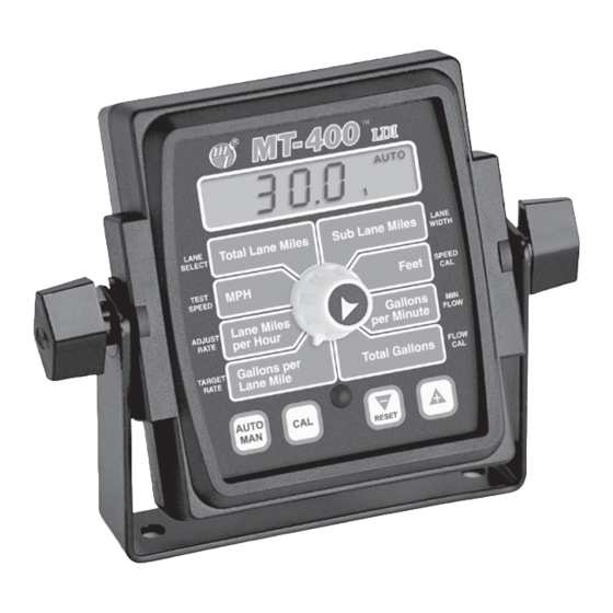
MT-400 Console Func tions The MT-400 features a large, easy-to-read liquid crystal display, lighted Brite-Knob™ rotary dial and lighted panel for night use. TOTAL LANE MILES: SUB LANE MILES: Keeps a running count of the total Counts lane miles of application. Can miles of application. -
Page 13: Calibration
Calibration Entering Calibration Values To enter or change any of the system’s calibration values, MANAUTO you must enter calibration mode. Turn all lane switches off CALHOLD or put the Run/Hold switch in HOLD position. Press and hold v 1 2 3 4 the CAL button for 3 seconds, until the red light comes on and CAL appears on the display. -
Page 14: Exiting Calibration
Calibration (cont) Entering Calibration Values (cont) SPEED CAL: This position is used to calibrate the speed MANAUTO sensor for accurate speed and distance measurement. CALHOLD CALHOLD When this position is v 1 2 3 4 selected, the display will Feet SPEED alternately show, every Total Lane Miles... -
Page 15: Drive Shaft Speed Sensor Calibration
Calibration (cont) Drive Shaft Speed Sensor Calibration Because the difference is wheel-to-drive shaft ratios, it is difficult to determine a calibration value for installation on a drive shaft by measuring a wheel. You must start with an estimated calibration value and then fine-tune the calibration. -
Page 16: Entering Flowmeter Calibration Values
Flow Cal Tag Illustration 10 Your Micro-Trak flowmeter has been tested at the factory and assigned a “FLOW CAL” value to make it operate properly with the MT-400 console. This number is stamped on the metal tag attached to the flowmeter. See Illustration 10. This is a starting point only. -
Page 17: Fine-Tuning Speed/Distance Calibration Value
Calibration (cont) Fine-Tuning Speed/Distance Calibration Value NOTE: If you let go of the “+” and “-” keys while you are In order to achieve accurate measurements, each step in this fine tuning procedure should be performed as precisely as adjusting the distance value, the console will wait to make possible. -
Page 18: Fine-Tuning Calibration
Calibration (cont) Fine-Tuning Flowmeter Calibration NOTE: Once a value has been selected for This procedure is used to verify and fine-tune the flowmeter calibration. Every flowmeter is calibrated with water and adjustment, the display will stop alternating stamped with a calibration value. Enter that value as a between the two values. -
Page 19: Calibration Log Sheet
Calibration (cont) Calibration Log Sheet Serial No. ____________ Min Flow: Adjust Rate: Target Rate: Width Cal left center right (Boom Width) Speed Cal: Mode Sel: Test Speed: Comments:... -
Page 20: Pre-Application System Checkout
Pre-Application System Checkout Before beginning actual spraying, perform the following Turn all active lane control switches ON. Make certain “pre-application” procedure to ensure that your valve system is in manual mode, turn rotary switch to the APP. settings, nozzle selection and desired speed range will allow RATE position and hold “-”... -
Page 21: Operation
Operation Illustration 13 Switches, Buttons and Display CONSOLE MANAUTO The MT-400 control panel features a large, easy-to-read back- CALHOLD lit liquid crystal display, exclusive Brite-Knob™ dial and back- v 1 2 3 4 lit panel for night operation. POWER SWITCH Total Lane Miles Sub Lane Miles LANE... -
Page 22: Rotary Switches
Operation (cont) Rotary Switches ROTARY SWITCH WARNING DEVICE During normal operation, you can view any one of eight The console is equipped with a RED warning light. The monitored functions by turning the rotary switch to the light will automatically turn on and flash when the actual appropriate position. -
Page 23: Resetting System Counters
Operation (cont) Resetting System Counters Illustration 14 The TOTAL LANE MILES, SUB LANE MILES, FEET AND TOTAL GALLONS counters maintain a running count during operation MANAUTO regardless of the position of the rotary switch . When any of CALHOLD these counters reach their maximum capacity, or when you v 1 2 3 4 want to start a new count, the value in the register may be reset to zero by performing the following routine. -
Page 24: Troubleshooting
PLEASE DO NOT OPEN lodged in the flowmeter. THE CONSOLE. Your system is protected by a warranty, and Micro-Trak will gladly correct any defect. 6553.5 MESSAGE DISPLAYED IN RATE MODE If this number appears when your equipment is standing still,... -
Page 25: Checking Individual Components
Troubleshooting (cont) Checking Individual Components RUN/HOLD HALL-EFFECT SENSOR Illustration 15 Caution: Improper connection or voltage could damage the Hall-Effect sensor. The Hall-effect sensor works similar to a reed switch, but requires power in order to function. This particular type of Hall-effect sensor “closes” when near the south pole of a magnet and is otherwise “open”. -
Page 26: Checking Console Inputs
Troubleshooting (cont) Checking Console Inputs SERVO VALVE CONTROL SIGNAL If there is no response from any of the following tests, refer to the main wiring diagram on the previous page to locate the With the console turned ON, put the console in MANUAL next connector in line toward the console and repeat the test mode and turn the lane control switch ON. -
Page 27: Wiring Diagram
Troubleshooting (cont) MT-400 Wiring Diagram MT-400 LDI CONSOLE 10-PIN METRI-PACK SHROUD 10-PIN METRI-PACK TOWER 10-PIN METRI-PACK SHROUD 10-PIN METRI-PACK TOWER... -
Page 28: Plumbing Troubleshooting Chart
Troubleshooting (cont) Plumbing Troubleshooting Chart SYMPTOM POSSIBLE CAUSE POSSIBLE SOLUTION Clean Strainer Loses Pressure in MAN Pump Airlock Larger Hoses Larger Hoses and Fittings Little or No Pressure adjustment in MAN Too much Restriction in Servo Loop No Sharp Bends Pump Starved or too Small Larger Hoses Too Much Agitation... -
Page 29: Plumbing Guidelines
Plumbing Guidelines General PUMP In order for your sprayer to function properly, it must be correctly plumbed. The system diagram (page 11) shows the The pump must have enough capacity to satisfy the agitation, plumbing configuration that works best with the MT-400. servo and flowmeter sections of the plumbing. -
Page 30: Appendices
Appendices... -
Page 31: Appendix A Flowmeter Assembly
Appendix A PLEASE NOTE: The turbines have magnets built into the fins. There are no visible magnets on the inside of the Flowmeter Assembly cavity. On a flat surface, place each housing half on end. Set and spin the turbine in each half. It should spin freely. IMPORTANT: Opening the flowmeter will void the Flow If is does not spin freely, remove the turbine, wipe the Calibration value assigned to your unit. -
Page 32: Appendix B Conversion Chart
Appendix B Conversion Chart English to Metric Metric to English When You Know Multiple By To Find When You Know Multiple By To Find LINEAR MEASUREMENT LINEAR MEASUREMENT inches 25.4 millimeters millimeters .039 inches feet 0.305 meters meters 3.28 feet yards 0.914 meters... -
Page 33: Appendix C Replacement Parts List
Appendix C Replacement Parts List The following replacement parts are available from your dealer or distributor, or directly from: Micro-Trak Systems, Inc. P.O. Box 99, 111 East LeRay Avenue Eagle Lake, MN 56024-0099 When ordering parts, please list the model number of your console, and the description and part number of each part that you want to order. -
Page 34: Notes
NOTES... - Page 36 1305 Stadium Road, Mankato, MN 56001-5355 U.S. and Canada: (800) 328-9613 Phone: (507) 257-3600 www.micro-trak.com • trakmail@micro-trak.com ©2004 • Micro-Trak Systems, Inc. • Printed in the U.S.A. P/N 14757 Rev. 1...
Need help?
Do you have a question about the MT-400 LDI and is the answer not in the manual?
Questions and answers