Table of Contents
Advertisement
Quick Links
Advertisement
Table of Contents

Subscribe to Our Youtube Channel
Related Manuals for micro-trak MT-3405 LR F


Summary of Contents for micro-trak MT-3405 LR F
- Page 1 MT-3405 F AUTOMATIC RATE CONTROLLER REFERENCE MANUAL...
- Page 2 Please read the manual carefully and follow the instructions as they apply to your usage. If you do encounter a problem that cannot be corrected by reviewing this manual, consult your dealer or distributor, or contact a Micro-Trak technician for assistance. Toll Free in U.S. or Canada: (800) 328-9613 or (507) 257-3600 Fax: 507-257-3001 E-mail: trakmail@micro-trak.com...
- Page 3 * Some limitations apply. See warranty statement for details. At Micro-Trak Systems, we believe a product that delivers quality and performance at a low cost is what is needed to help today’s operator and the operator of the future compete in the world mar ket.
-
Page 4: Table Of Contents
Table of Contents Warranty...................................... 3 Table of Contents ...................................4-5 Basic Overview of Typical Installation ..........................6 Component Parts and Assembly Hardware ........................7-8 Installation .....................................8-16 Required Tools ......................................8 Mounting the Display Console ................................9 Electrical Installation ....................................9 Speed Sensor Installation ................................10-11 Magnets ......................................10 Attaching Magnets .................................. -
Page 5: Table Of Contents
Table of Contents (cont) Troubleshooting (cont) ..............................29-34 Checking Individual Components ............................30, 32-33 Console .......................................30 Harness .......................................30 Electrical Interface ..................................30 Power ........................................30 Accessory Power ..................................... 30 Magnetic Hall-effect Speed and Flow Sensors ........................32 Console Inputs ....................................32 Speed Input ....................................32 Flow Input ..................................... - Page 6 Component Parts and Assembly Hardware Before beginning installation, check the carton contents for the following items: 5’ Hall-effect Flow Sensor Cable 1” Electric Console Mount Kit MT-3405 F Console with threaded sensor Servo Valve P/N 13254 P/N 13775 P/N 13096 P/N 11218 MT-3405 F AUTOMATIC RATE CONTROLLER...
- Page 7 MT-3405F System Layout...
- Page 8 MT-3405F Wiring Diagram...
-
Page 9: Basic Overview Of Typical Installation
Basic Overview of Typ i cal Installation Hall-E ect Speed Sensor (or Vansco or Optional Radar or GPS Speed Sensor) Magnets on Hub of Non-driven Wheel Local Access MT-NH3 II Console Speed Connection with Vacuum Mount Battery Main Harness Hitch Connection Rear Speed Connection NH3500 Kit or Liqui er Kit... -
Page 10: Installation
Installation Tools Needed to Install MT-3405F Mounting the Display Console • Screwdrivers • Pliers • Set of Wrenches • Wire Cutter Select a mounting location which seems most workable, and • Electric Drill and Bits • Hacksaw that best fits your needs. It should be con ve nient to reach •... -
Page 11: Speed Sensor Installation
(ATV’s), a minimum of two magnets Test magnet are required. Illustration 3B should alternately The magnets provided by Micro-Trak are marked with a South attract and repel. North dashed line on the SOUTH pole side of the magnet. See Illustration 3A. -
Page 12: Magnets
Installation (cont) Magnet Installation (cont) EXAMPLE IN ENGLISH/TURF UNITS Magnet If your revolution measurement is 97 inches, dividing that Drill lug number by 20 gives you a value of 4.85. Rounding 4.85 up to bolt hole the nearest even number is 6. For this example, the minimum and bend number of magnets required is 6. -
Page 13: Connecting The Speed Sensor Cable
It features state-of-the-art electronic design/ manufacturing, rugged aluminum housing and complete Vansco Radar Speed Sensor testing and certification. Contact a Micro-Trak dealer/distributor for de tails on any of these products, or call Mi cro-Trak Systems, Inc. at 1-800-328-9613. -
Page 14: Mounting And Plumbing Flowmeter
Installation (cont) Mounting and Plumbing Flowmeter Illustration 5 The Flowmeter must be installed in the boom supply line Hose Clamps* Sprayer Line* after any strainers, return lines, or valves, but before the ¾” NPT Male Fitting* boom shut-off valves. Se cure ly mount flow me ter (hardware not supplied) in a vertical position in an area away from Flowmeter Hose Clamps*... -
Page 15: Pressure Relief Valve
Installation (cont) Pressure Relief Valve Range Adjust Valve If you have a positive displacement pump or a cen trif u gal pump capable of generating excessive pressure, you must With oversized pumps, it may be necessary to install a range in stall a pressure relief valve and adjust it to a safe max i- adjust valve. -
Page 16: Boom Shut-Off Valves
Installation (cont) Illustration 10 Relief Valve The relief valve is used to “dump” pressure when your boom valves are turned off. Whenever all the boom control switches are turned off, or when HOLD is selected with the master switch, the relief valve should be open. Use this plumbing illustration (See Illustration 10) as your pattern for proper RELIEF SOLENOID installation if your relief valve has a flow-through port. -
Page 17: Console Functions
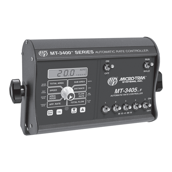
MT-3405 F Console Func tions The MT-3405 F features a large, easy-to-read liquid crystal display, lighted Brite-Knob rotary dial and lighted panel for night use. ™ SUB AREA: TOTAL AREA: Counts acres (hectares) worked. Can be used to Keeps a running count of the total acres measure individual fields or to perform periodic checks. -
Page 18: Calibration
Calibration Illustration 12 Entering Calibration Values English or Metric? MANAUTO CALHOLD HOLD V 1 2 3 4 5 The MT-3405 F is capable of displaying in for ma tion in Amer- TOTAL AREA SUB AREA BOOM WIDTH i can En glish or standard Metric measurement. SELECT TEST SPEED... -
Page 19: Setting Individual Boom Width
Calibration (cont) Entering Calibration Values (cont) BOOM SEL: To enter or change any of the system’s calibration values, This po si tion is used to se lect the boom sec- you must enter calibration mode. To enter calibration mode, tion to be cal i brat ed. With the ro ta ry switch in this po si- STOP the vehicle, place the run/hold switch on the front tion, the dis play will panel in HOLD and press and hold the CAL button until “CAL”... -
Page 20: Banding Application Calibration
Calibration (cont) Illustration 15 Entering Calibration Values (cont) Banding Application Calibration In banding applications, you will still need to enter the total width of each boom section so that area counts correctly, but you must also calculate the percentage of your total width the band is covering and reduce your target rate to match. -
Page 21: Drive Shaft Speed Sensor Calibration
24. FLOW CAL: Your Micro-Trak flowmeter has been tested at the factory and This po si tion is used to cal i brate the flow me ter assigned a “FLOW CAL” value to make it operate properly for ac cu rate liquid mea sure ment. - Page 22 Operation Switches and Buttons CONSOLE MANAUTO CALHOLD The MT-3405 F control panel features a large, easy-to-read HOLD 1 2 3 4 5 backlit liquid crystal display, exclusive BriteKnob dial and TOTAL AREA SUB AREA BOOM WIDTH SELECT backlit panel for night operation. TEST SPEED DISTANCE...
- Page 23 Displays the actual gallons (liters) per minute being applied. and the rotary switch is turned to FLOW RATE, pressing the When the MT-3405 is used in conjunction with a Micro-Trak “+” and/or “-” buttons will increase or decrease the flow rate...
-
Page 24: Test Speed
Operation (cont) Resetting System Counters The TOTAL AREA, SUB AREA, DISTANCE and TOTAL FLOW Illustration 19 counters maintain a running count during operation regardless of the position of the rotary switch. When any of these counters reach their maximum capacity, or when MANAUTO CALHOLD you want to start a new count, the value in the register... - Page 25 Pre-Field Sys tem Checkout Now is a good time to confirm that GPA, GPM, MPH, WIDTH and PSI all coincide with the nozzle man u fac tur- er’s charts. PSI may be slightly higher than indicated by Before beginning actual spraying, perform the following the charts due to pressure drop across the boom valves, “Pre-field”...
-
Page 26: Troubleshooting
PLEASE DO NOT OPEN THE Calibration on page 25. CONSOLE. Your system is protected by a warranty, and Micro-Trak will gladly correct any defect. Check the mounting position of the flowmeter. With lower flow rates, the meter should be mounted vertically. Also... -
Page 27: Console
Troubleshooting Checking Individual Components TRAK-STAR ULTRASONIC SPEED SENSOR CONSOLE The only way to field test a console is to con nect it to a Make certain that the Trak-Star is emitting a “crackling” sound. If not, check for power between pins A (WHITE wire) harness on a vehicle with a known working console or install and B (BLUE wire) of the adapter cable’s 6-pin connector. -
Page 28: Console Inputs
Troubleshooting Console Inputs SERVO VALVE CONTROL SIGNAL If there is no response from any of the following tests, refer to the main wiring diagram on the pre vi ous page to locate the Flip the power switch to ON, put the console in MANUAL next connector in line to ward the con sole and repeat the test mode, place the Run/Hold switch in the RUN position and at that con nec tor. - Page 29 Plumbing Troubleshooting Chart SYMPTOM POSSIBLE CAUSE POSSIBLE SOLUTION Clean Strainer Loses Pressure in MAN Pump Airlock Larger Hoses Larger Hoses and Fittings Little or No Pressure adjustment in MAN Too much Restriction in Servo Loop No Sharp Bends Pump Starved or too Small Larger Hoses Too Much Agitation Reduce Agitation...
-
Page 30: Plumbing Guidelines
Plumbing Guidelines General PUMP In order for your sprayer to function properly, it must be correctly plumbed. The MT-3405F System Layout on page The pump must have enough capacity to satisfy the agitation, 7 shows the plumbing configuration that works best with servo and flowmeter sections of the plumbing. -
Page 31: Valve Purpose And Adjustments
Plumbing Guidelines (cont) Valve Purpose and Adjustments TANK SHUT-OFF VALVE THROTTLE VALVE The tank shut-off valve is for convenience only. It allows you The throttle valve limits your high end to maximize servo performance. Start with throttle valve fully open and to work on the plumbing without draining the tank. - Page 32 MT-3405F Plumbing Overview Diagram (cont) For Oversized Pumps Illustration 21 Range Adjust Valve Tee “C” Tee “A” For Positive Displacement Pumps Illustration 22 Pressure Relief Valve Tee “C” Tee “A” If Optional Relief Valve Kit is Used Illustration 23 Servo Valve Relief Valve Tee “B”...
-
Page 33: Appendices
Appendices... -
Page 34: Appendix A: Optional Speed Sensor Mounting Installation
Appendix A Optional Speed Sensor Mounting Installation Implement Wheels Speed Sensor and Bracket Prepare and install magnet clips as shown. Place a magnet at the end of each clip (longest side of ¼” Bolts, magnet should point in the direction of wheel rotation). Lockwashers Place a cable tie (ribbed side toward magnet) around and Nuts... - Page 35 Hall-effect speed sen sor must alternate as tie as close to sensor assembly as possible. the shaft is turned. The magnets provided by Micro-Trak are NOTE: If you are using more than two magnets, please marked with a punched dashed line on the SOUTH pole side follow the directions on page 12.
- Page 36 Appendix B Fine Tuning Speed/Distance Calibration Value This procedure is used to verify the calibration of the When the display shows distance (“CAL” is not system. In order to achieve accurate mea sure ments, each displayed), ver i fy wheth er the number displayed is the step in this fine tun ing procedure should be per formed as ex act dis tance you drove (with in “+”...
- Page 37 Appendix C Fine Tuning Flowmeter Calibration This procedure is used to verify and fine-tune the Once the display again begins alternating, you will flowmeter calibration. Every flowmeter is calibrated with notice that the flowmeter calibration value has changed. water at the factory and stamped with a calibration val ue. If the TOTAL FLOW value is correct, write down the new Enter that value as a starting point and use this pro ce dure to flowmeter calibration value.
- Page 38 Appendix D NOTE: The turbines have magnets built into the fins. There are no visible magnets. Flowmeter Assembly On a flat surface, place each housing half on end. Set and spin the turbine in each half. It should spin freely. If it does IMPORTANT: Opening the flowmeter will void the Flowmeter not spin freely, remove the turbine, wipe the shaft and try Calibration value assigned to your unit.
-
Page 39: Appendix B: Various Ball Valve Configurations
Appendix E Various Ball Valve Configurations Basic 3 & 4-wire configurations are shown below. If you need assistance for wiring other than shown, contact Micro-Trak for wiring instructions. 12-volts Valve Switching Wire Ground Switching Wire Relay + Relay – Valve Motor –... - Page 40 NOTE: Do not operate system with Micro-Trak Electric Your MT-3405 F is factory calibrated to operate the standard Micro-Trak Electric Servo Valve. The system is also capable of Servo Valve installed when the 12-volt control driver mode using standard 12-volt control valves in place of the Micro- is activated.
-
Page 41: Appendix C: Conversion Chart
Appendix G Conversion Chart English to Metric Metric to English When You Know Multiple By To Find When You Know Multiple By To Find LINEAR MEASUREMENT LINEAR MEASUREMENT inches 25.4 millimeters millimeters .039 inches feet 0.305 meters meters 3.28 feet yards 0.914 meters... - Page 42 Appendix H Replacement Parts List The following replacement parts are available from your dealer or distributor, or directly from: Micro-Trak Systems, Inc. P.O. Box 99, 111 East LeRay Avenue Eagle Lake, MN 56024-0099 When ordering parts, please list the model number of your console, and the description and part number of each part that you want to order.
- Page 43 Appendix I MT-3405F Non-Bulkhead Wiring Diagram MT 3405 CONSOLE 3-PIN METRI-PAK 10-PIN METRI-PACK TOWER 10-PIN METRI-PACK SHROUD 10-PIN METRI-PACK TOWER 630 SHROUD 10-PIN METRI-PACK SHROUD 10-PIN METRI-PACK SHROUD 10-PIN METRI-PACK TOWER 3-PIN METRI-PAK 630 TIOWER 10-PIN METRI-PACK TOWER 10-PIN METRI-PACK SHROUD 10-PIN METRI-PACK TOWER 10-PIN METRI-PACK SHROUD 10-PIN METRI-PACK TOWER...
- Page 44 Manufactured in U.S.A. by: 111 East LeRay Ave. • Box 99 • Eagle Lake, MN • 56024-0099 Toll-Free: 800-328-9613 507-257-3600 • Fax 507-257-3001 www.micro-trak.com • trakmail@micro-trak.com Printed in U.S.A. © 2004 Micro-Trak Systems, Inc. P/N 13773 Rev 2...
Need help?
Do you have a question about the MT-3405 LR F and is the answer not in the manual?
Questions and answers