Table of Contents
Advertisement
Quick Links
Advertisement
Table of Contents
Troubleshooting

Related Manuals for micro-trak SprayMate Plus


Summary of Contents for micro-trak SprayMate Plus
- Page 2 If you do encounter a problem that cannot be corrected by reviewing this manual, consult your dealer or distributor, or contact a Micro-Trak® technician for assistance. U.S. or Canada: Toll-free (800) 328-9613 or (507) 257-3600 Fax: 507-257-3001 www.micro-trak.com •...
-
Page 3: Micro-Trak ® Warranty
Eagle Lake, MN 56024-9650 At Micro-Trak® Systems, we believe a product that delivers quality and performance at a reasonable cost is what is needed to help today’s operator and the operator of the future compete in the world mar ket. -
Page 4: Table Of Contents
Table of Contents ® Micro-Trak Warranty Table of Contents Component Parts and Hardware System Overview Wiring Diagram Installation Overview Installation Steps Mounting the Console Electrical Installation Branch Harness Connections Speed Sensor Options Optional Equipment - Switches Plumbing Overview - Bypass... -
Page 5: Component Parts And Hardware
Component Parts and Hardware AUTO SprayMate Plus Console Reference Manual Power Switch Kit Run/Hold Switch Kit P/N 18700 P/N 18770 P/N 21779 P/N 21778 Branch Harness Power Cable w/Weather Pack Tower Conn. P/N 14315 P/N 18532 Console Mount Kit 120” 10-pin Extension Cable 14”... -
Page 6: System Overview
System Overview Note: Branch Harness diagram shown is P/N 18532 w/Weather Pack Tower connectors. The P/N 18280 cable w/ Weather Pack Shroud con- nectors has the same layout. -
Page 7: Wiring Diagram
Wiring Diagram Note: Branch Harness shown is P/N 18532 w/Weather Pack Tower connectors. The P/N 18280 cable w/ Weather Pack Shroud connec- tors has the same wiring layout. -
Page 8: Installation
Installation Overview Install the SprayMate™Plus console and system components by following the recommended sequence of steps. Your installation may not include some of these steps; some equipment is optional and some components may already be installed. All installations must follow Calibration and Pre-Field System Checkout steps (9,10) to ensure safe and accurate operation of system. -
Page 9: Mounting The Console
Installation (cont.) Mounting the Console Select a mounting location which seems most workable, and best fits your needs. It should be convenient to reach and highly visible to the operator. DO NOT INSTALL IN A POSITION THAT OBSTRUCTS THE VIEW OF THE ROAD OR WORK AREA. Whenever possible, avoid locations that expose the console to direct sunlight, high temperature, strong chemicals or rain. -
Page 10: Electrical Installation
Installation (cont.) Electrical Installation This section explains how to hook-up your SprayMate Plus to a 12VDC power connection and On/Off Switch, and wiring information about section shut-off valves connections. The SprayMate Plus must be connected to a 12VDC negative ground electrical system. ROUTING HARNESS AND CABLING Avoid ar eas where the ca ble may be sub ject ed to abra sion or exces sive heat. -
Page 11: Branch Harness Connections
Installation (cont.) Branch Harness Connections Note: Branch Harness shown is P/N 18532 w/Weather Pack Tower connectors. The P/N 18280 cable w/ Weather Pack Shroud connectors has the same wiring layout. -
Page 12: Speed Sensor Options
ASTRO SERIES OR OTHER GPS SPEED SENSOR INTERFACES The SprayMate Plus is designed to easily connect to the Micro-Trak Astro series speed sensor. It also may be used with most GPS speed sensors that output a pulsed signal, such as the Squibb-Taylor® SkyTrak or Dickey-John® GPS speed sensors. An adapter cable may be required. -
Page 13: Optional Equipment - Switches
The connector labelled “SafeGuard Run/Hold” is wired Normally Open. The default polarity for the SprayMate Plus Run/Hold circuit is preset to “Closed”, meaning pressure on the switch tip causes the system to “Hold”. See figure 6. The polarity setting can be accessed in Special Calibration settings (see page 23) - it is called “Hold Input Polarity”. -
Page 14: Plumbing Overview - Bypass
Installation (cont.) SprayMate Plus Plumbing Overview Bypass Configuration - Flow through servo bypasses flowmeter... -
Page 15: Plumbing Overview - Inline
Installation (cont.) SprayMate Plus Plumbing Overview In-Line Configuration - Flow through servo is inline with flowmeter... -
Page 16: System Components
* NOT SUPPLIED Flipping the flowmeter periodically (black nylon and stainless Figure 8 steel Micro-Trak® manufactured models) to reverse the flow will greatly extend the life of the flowmeter by evening out bearing wear. Care and Maintenance At end of application season, thoroughly flush Flowmeter with clean water, and drain completely. - Page 17 Installation (cont.) System Components Bypass Valve For oversized pumps Bypass Valve With oversized pumps, it may be necessary to install a bypass valve. This valve allows excess flow to return to Tee “C” the tank. This in turn reduces the pump output to the rest of the system.
-
Page 18: Feature Summary
Feature Summary Basic Features • Operates in LIQUID or NH3 application modes in Metric, English or Turf units: - English: Area units are acres, distance is feet, flow is gallons or lbs-NH3 per minute and application rates are in gallons or lbs-N per acre. - Metric: Area is measured in hectares, distance is in meters, flow is liters or kg-NH3 per minute and application rates are in liters or kg-N per hectare. - Page 19 Audible alarm output (can be disabled) for notification of Rate errors over ‘Rate Alarm Threshold’ or Tank level below set point, or Pressure above or below Hi or Low alarm level. • Optional Pressure Sensor to monitor system pressure. SprayMate Plus can also be configured for pressure based flow control. •...
-
Page 20: Spraymate Plus Console Func Tion Summary
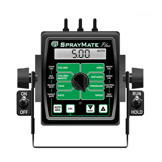
SprayMate Plus Console Func tion Summary The SprayMate Plus features a large, easy-to-read liquid crystal display, easy-to-use rotary dial and lighted panel for night use. The console also includes section switches, an audible alarm, and a serial port. VOLUME (1) (2) (3): AREA (1) (2) (3): Displays the total Keeps a running... -
Page 21: Calibration
Calibration Before operating the SprayMate™ Plus, it is necessary to calibrate it for the intended operation. The first step is choosing intended UNITS (English, Metric, or Turf) in Special Calibration, page 23 - this will also load default values. We recommend to complete all Special Calibration adjustments before returning to Calibration setup. CALIBRATION STEPS: 1. -
Page 22: Calibration Positions
Calibration (cont.) Calibration Positions FLOW WIDTH This po si tion cal i brates the system to the flow- Adjust the effec tive working width, in inch es me ter factory setting. The flowmeter is calibrated (meters) for each boom section. with water at the factory and assigned a “Liquid Enter a value of “0”... -
Page 23: Special Calibration
Special Calibration Special Calibration mode accesses important system parameters and settings. The UNITS position must be set before changing any other Calibration or Special Calibration settings. These settings enable or disable other setting options to adjust applicable parameters: • UNITS: determines which unit of measurement is used •... - Page 24 APPLICATION ID is included with defines the intended simulated speed in MPH (km/H). the Totals Data List and Equipment List information. See Appendix E for details. Setting to 0 (Off ) will (Micro-Trak® protocol only) disable the function.
- Page 25 (maximum) value for Pressure Sensor. Default setting feature. When transitioning from HOLD to RUN, it is 150 PSI for Micro-Trak Pressure Sensor P/N 18757. provides time for motorized valves to operate and Adjust it to 300 PSI for Micro-Trak P/N 18758.
- Page 26 VRA information through the serial P-FLO: Threshold value turns on power to Multifunction port. Choices are Micro-Trak or Raven (model 660) output based on flow rate, proportional to active width. Default is Micro-Trak protocol. Example: If the threshold is set to 10gpm while running only...
- Page 27 VALVE POLARITY - STD ONLY Location: PAGE 4 - RATE Description: In STD Output, this defines operation of the flow control valve - choose Bypass or Inline plumbing configuration. When using a Micro-Trak Electric Motor Driver, choose Bypass. Default setting is Bypass.
- Page 28 Location: PAGE 5 - DISTANCE Description: This setting allows the user to reverse the polarity of section inputs. This may be useful when connecting a separate device to the SprayMate Plus system for automatic section control. Default is 12v. FIXED MINIMUM FLOW...
-
Page 29: Operation
Operation Make sure your system is properly calibrated before beginning to apply product. We also recommend completion of the Pre Application System Checkout described on page 32 prior to beginning any operations. Manual Operation This mode sets and maintains a steady flow rate (GPM) not affected by changes in vehicle speed. The overall application rate (GPA) will vary depending on speed (slow vehicle speed = increased application rate, fast speed = lower application rate.) Manual mode is most useful for system set up, spot applications, etc. -
Page 30: Console Controls
Operation (cont.) Console Controls ON/OFF When the SprayMate Plus console is turned on INCREASE/ APPLICATION RATE ADJUST: SWITCH (except when starting SPECIAL CALIBRATE) the In the RATE position, these buttons are DECREASE display shows the following information for used to increase or decrease the application approximately 1 second each: rate. -
Page 31: Additional System Features
The Emergency Stop accept variable target rates from a prescription feature helps prevent over-application and map. If the GMC does not include ‘Micro-Trak’ chemical spills if the Flow signal is lost. as a supported serial controller, then the Raven... -
Page 32: Pre-Field Sys Tem Checkout
Pre-Field Sys tem Checkout Before beginning actual spraying, perform the following “Pre-Field” procedure to ensure that your valve settings, nozzle selection and desired speed range will allow the SprayMate™ Plus to provide the required application control. This procedure should be repeated for each new nozzle se lec tion and/or application rate. -
Page 33: Troubleshooting
Troubleshooting Messages/Warnings Indicates a corrupt calibration value. Can only be cleared by entering Calibration or Special Calibration modes, checking and/or changing settings and exiting to save. The message alerts the user that the currently selected counter will be cleared if the reset button is held for 2 seconds. -
Page 34: General
CONSOLE. Your system is protected by a warranty, and and be sure this is entered in the console’s “FLOW CAL” Micro-Trak® will gladly correct any defect. position. If the meter has been used for some time, wear may have changed the Flow Cal value. See Fine-Tuning Many problems are the result of mistakes in installation or Flowmeter Calibration in Appendix D. -
Page 35: Checking Individual Components
12VDC to operate. Also, the Hall- assess it on a Micro-Trak® demonstration dis play. effect sen sor re quires al ter nat ing magnetic po lar i ties in or der HARNESS to switch. -
Page 36: Checking Console Inputs
Troubleshooting (cont.) Checking Console Inputs CONSOLE INPUTS FLOWMETER Shaking the Flowmeter end to end should pro duce a “rattling” If there is no response from any of the following tests, refer to sound (shaft end play). Blowing in the meter from either end the main wiring diagram to locate the next connector in line should spin the turbine freely. -
Page 37: Plumbing Troubleshooting Chart
Plumbing Troubleshooting Chart SYMPTOM POSSIBLE CAUSE POSSIBLE SOLUTION System loses pressure in MANUAL Pump Air-lock • Clean strainer • Install larger hoses Insufficient pressure adjustment in Too much flow restriction in servo loop • Install larger hoses and fittings MANUAL •... -
Page 38: Appendices
Appendices... -
Page 39: A - Remote Run/Hold Kit Installation
Appendix A - Remote Run/Hold Kit Installation The Remote Run/Hold Sensor has a black body and joins to Lift Wheel Mounting the branch har ness ca ble labeled “Remote R/H”. It is used Sensor (Black body) as an implement switch and automatically activates the Run/Hold function as im ple ment is raised and lowered. -
Page 40: B - Magnetic Speed Sensor Installation
5. Rounding 5 up to the nearest even number is 6. For this South example, the minimum number of magnets required is 6. The magnets provided by Micro-Trak® are marked with North South a punched dashed line on the SOUTH pole side of the Figure 22 magnet. - Page 41 Appendix B- Magnetic Speed Sensor Installation (cont.) Wheel Mounting Implement Wheels Speed Sensor and Bracket 1. Secure magnets mechanically or with epoxy. 2. Rigidly mount sensor mounting bracket to the wheel ¼” Bolts, assembly. Cut or bend “L” bracket as required for proper Lockwashers and Nuts positioning of sensor.
- Page 42 When distance is set, tight en nuts to lock sensor in detect ed by the Hall-effect speed sen sor must alternate as place. the shaft is turned. The magnets provided by Micro-Trak® • Secure sensor cable to frame with cable ties. Place first are marked with a punched dashed line on the SOUTH pole tie as close to sensor assembly as possible.
-
Page 43: C - Fine Tuning Speed/Distance Calibration Val Ue
Appendix C - Fine Tuning Speed/Distance Calibration Val ue This procedure is used to verify the Speed/Distance 4. With the rotary dial still at DISTANCE (SPEED CAL), press calibration. In order to achieve accurate measurements, and hold the CAL button for one second. Once the each step in this fine tuning procedure should be con sole is in “CAL,”... -
Page 44: D - Fine Tuning Flowmeter Calibration Value
Appendix D - Fine Tuning Flowmeter Calibration Value This procedure is used to verify and fine-tune the flowmeter With the console still in the VOLUME position, enter calibration. Every flowmeter is calibrated with water at the calibration, hold the CAL button until the red warning factory and stamped with a calibration val ue. -
Page 45: E - "Quick Start" Function
Appendix E - “Quick Start” Function There are two different Quick Start methods, “Quick Start - SPEED” and “Quick Start – VALVE”, which can be enabled for use in Automatic operating mode. Each method uses a separate set of Special Calibrate parameters, and only one method can be enabled at a time (the other must be disabled). -
Page 46: F - Nh3 Control
Appendix F - NH3 Control Wiring Connections for NH3 Additional Valves (For multi-section only) To Console Servo Flowmeter Shut-off Valve... - Page 47 Appendix F - NH3 Control Typical Installation for NH3 GPS Speed Sensor SprayMate™ Plus (Other options available) Console Battery Main Harness Hitch Connection Liqui er™ Series Heat Exchanger Nurse Tank...
- Page 48 Appendix F - NH3 Control Connection to Liquifier™ NH3 Kits Branch Harness An NH3 system can be connected to SprayMate™ Plus using the Branch Harness, P/N 18532, shown here. Choose an appropriate length extension cable (for example, P/N 14316 shown below). See Appendix M for various extension lengths.
- Page 49 Appendix F - NH3 Control Liquifier Installation LIQUIFIER KIT INSTALLATION Remove any existing metering valves. If the old metering valve has a built-in manifold, it is recommended to install a separate new manifold for the Liquifier™ kit. Another option, although not recommended, is to use the existing manifold, making certain the old metering valve is in the maximum open position to allow for minimal restriction of flow through the plumbing.
- Page 50 Appendix F - NH3 Control Liquifier™ Series - Vapor Line Installation FOR ALL NH3 KITS Locate the 1/2” EVA vapor hose supplied with the kit. Starting on one half of the tool bar, connect the 1/2” hose Weld the steel vapor tubes to the back of your liquid to the outside steel vapor tube.
- Page 51 Appendix F - NH3 Control Console Setup & Calibration for NH3 Application To begin setup the SprayMate™ Plus console for NH3 application, first enter Special Calibration mode: 1. Turn the console OFF. 2. For safety, place system in HOLD via the RUN/HOLD switch. 3.
- Page 52 This po si tion is used to cal i brate the system to the flow me ter for ac cu rate NH3 mea sure ment. The flowmeter has been calibrated at the factory. Enter the “Micro-Trak NH3 cal” number found on the plastic tag attached to the flowmeter.
- Page 53 Appendix F - NH3 Control Console Setup & Calibration for NH3 Application WIDTH Use the Increase/Decrease switches to adjust the number to the working width of your tool bar in inches (thousandths of meters). The “working” width is the width of ground being affected by any operation - for NH3, this equals the number of knives times the spacing.
- Page 54 Appendix F - NH3 Control Fine Tuning Flow Calibration Val ue - NH3 Systems This procedure is used to verify and fine-tune the flowmeter calibration. Every flowmeter is calibrated with water at the factory and stamped with a calibration val ue. Enter that value as a starting point and use this pro ce dure to fine-tune that value for your specific in stal la tion and NH3 application (Please refer to Flow Cal page 52).
- Page 55 Appendix F - NH3 Control Field Operation - Troubleshooting for NH3 Always follow accepted safety precautions. Make sure that equipment is in good operating order. Before connecting the nurse tank to the applicator, check the electric shut-off valve of the SprayMate™ Plus system for proper operation. After changing nurse tanks or after other periods of long shut-down, operate the system in MANUAL until the application rate stabilizes.
- Page 56 Appendix F - NH3 Control Flowmeter Assembly (FM-750 N) IMPORTANT: TO ASSEMBLE THE FLOWMETER Opening the flowmeter will void the Flow Calibration value assigned to your unit. However, you may Place the servo, flowmeter end up, in a vice or other suitable need to take the flowmeter apart for periodic cleaning or to fixture.
- Page 57 Appendix F - NH3 Control Flowmeter Assembly (FM-1500 N) IMPORTANT: Opening the flowmeter will void the Flow Calibration value assigned to your unit. However, you may need to take the flowmeter apart for periodic cleaning or to remove an obstruction. See Illustration below for flowmeter reassembly instructions.
-
Page 58: G - "Open Loop" Control & Closed Loop Override
Appendix G - “Open Loop” Control & Closed Loop Override Note: This feature can only be used with a PWM control valve. OVERVIEW Ideally an automatic control system is run using Closed Loop operation which uses feedback from a flow meter (or motor RPM sensor) to adjust the application rate based on ground speed. -
Page 59: H - Pulse Width Modulation (Pwm) Live Calibrate
Appendix H - Pulse Width Modulation (PWM) Live Calibrate LIVE CALIBRATE is only used in PWM Drive. See “SPECIAL” In Closed Loop, LIVE CALIBRATE allows the user to adjust CALIBRATE for information on setting the output to PWM the Min or Max PW factor and then immediately see how and selecting Open or Closed Loop operation. - Page 60 Appendix H - Pulse Width Modulation (PWM) Live Calibrate Closed Loop Operation When satisfied with the minimum flow rate and In Closed Loop operation, a flowmeter is available to measure the flow so all four calibrate factors can be programmed minimum PWM then press the CAL button to toggle interactively using the following procedure.
- Page 61 Appendix H - Pulse Width Modulation (PWM) Live Calibrate Open Loop Operation In Open Loop operation, a flowmeter is not available to 11. Select the FLOW @ MIN PW (Volume/Minute) position. measure the flow so a calibrated container must be used to This will enable a 30 second Timer when the pump is measure the actual flow using the following procedure.
- Page 62 Appendix H - Pulse Width Modulation (PWM) Live Calibrate Open Loop Operation 18. When satisfied that MAX PW has been set correctly, press the CAL button to toggle the pump off. If desired, the MAX PW can be written down for future reference. 19.
-
Page 63: I - Pressure Based Control
Appendix I - Pressure Based Control Enabling SprayMate™ Plus can be configured for Pressure Based Control by entering Calibration and adjusting the Flow Cal number to 0. In addition, MIN FLOW and MIN PRESSURE parameters must also be set or the system will not operate. The MIN PRESSURE parameter is only visible and accessible when Pressure Based Control has been enabled;... -
Page 64: J - Default Calibration Values
Flush Delay Time Flush Time Audible Alarm Enable Minimum Speed Alarm 0 MPH 0 kph 0 MPH Serial VRA Protocol Micro-Trak Micro-Trak Micro-Trak Manual Control Enable PWM Frequency (PWM) 200 Hz 200 Hz 200 Hz Flow @ MAX PW (PWM) -
Page 65: K - Radar Adapter Cables
Appendix K - Radar Adapter Cables In-Cab Case MX Series Britax Connector Vansco Radar Amp Connector P/N 18319 P/N 14926 Signal Ground DICKEY-john Radar Amp Connector P/N 14812 In-Cab John Deere Metri-Pack Connector P/N 14810 8000/9000 Series 1. Ground 1. Ground 2. -
Page 66: L - Conversion Chart
Appendix L - Conversion Chart English to Metric Metric to English When You Know Multiply By To Find When You Know Multiply By To Find LINEAR MEASUREMENT LINEAR MEASUREMENT inches 25.4 millimeters millimeters .039 inches feet 0.305 meters meters 3.28 feet yards 0.914... -
Page 67: M - Replacement Parts List
18758 Pressure Sensor - 300 psi max. 18764 Plus Series Single Pressure Sensor Harness Kit 18770 SprayMate Plus Reference Manual 21778 Run/Hold Switch Kit 21779 Power Switch Kit *The Console Mount Kit is available only as a kit, some parts are not available in individual components. -
Page 68: N - Electric Motor Driver - Setup & Connectivity
Appendix N - Electric Motor Driver - Setup & Connectivity This appendix features the PN01758 40A PWM EMD kit. Information on other models can be found online at: www.micro-trak.com/product/electric-motor-driver/. 40A PWM Electric Motor Driver The Electric Motor Driver (EMD) replaces the servo valve. - Page 69 Appendix N - Electric Motor Driver - Setup & Connectivity LED Codes & Module Diagram System Status LED Indicator Codes Single Status LED: flashing code repeats after pause - cycle controller power to clear fault code LED on steady Unit turned on and operating normally Steady Flashing Unit in HOLD.
- Page 70 PN18928 Relay Module to engage Pump 2 on demand. Set Multifunction Output for F-FLO (Fixed Flow Trigger) and enter threshold value in Special Calibration. Note: Micro-Trak offers a PN19963 2nd Motor EMD Enable & Motor Cable kit - includes PN18928 Relay Module & PN18420 Motor Cable. SprayMate Plus...
- Page 71 NOTES...
- Page 72 111 LeRay Ave. Eagle Lake, MN 56024-9650 Toll-Free: 800-328-9613 507-257-3600 • Fax 507-257-3001 www.micro-trak.com • email: trakmail@micro-trak.com © 2021 • Micro-Trak® Systems, Inc. • P/N 18770 • 111521...
Need help?
Do you have a question about the SprayMate Plus and is the answer not in the manual?
Questions and answers