
Related Manuals for micro-trak MT-3405 F II


Summary of Contents for micro-trak MT-3405 F II
- Page 1 MT-3405F ™ “Dual Display” automatic rate controller p e r a t i O n a n d a l i b r a t i O n e f e r e n C e a n u a l...
-
Page 2: Table Of Contents
Table of Contents Table of Contents ..................................2 Console Functions ..................................3 Calibration ....................................4-9 English/Metric Selection ..................................4 Calibration Key Function ..................................4 Entering Calibration Values ................................4-6 Radar or GPS Speed Sensor Calibration ............................6 Determining the Speed Cal................................7 Drive Shaft Speed Sensor Calibration ............................7 Test Speed ......................................7 Exiting Calibration .....................................7 Factory-loaded Calibration Values ..............................7... -
Page 3: Ii Console Func Tions
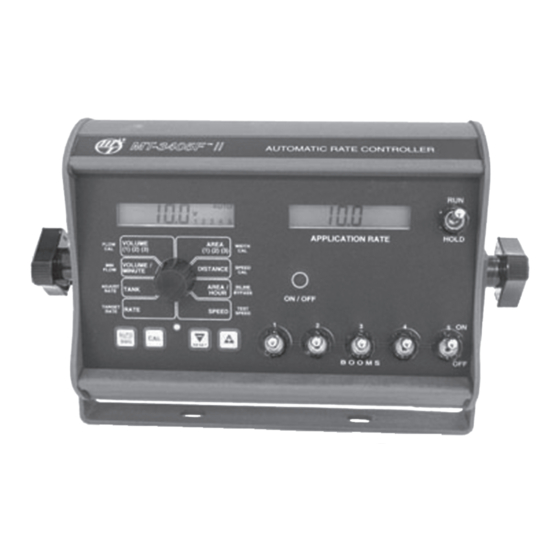
Overview of MT-3405F II Console Func tions The MT-3405F™ II features two large, easy-to-read liquid crystal displays and a lighted panel for night use. The right-hand display always shows the application rate and the left-hand display shows data selected by the rotary switch. -
Page 4: Calibration
Calibration - Loading Default Calibration Values English or Metric? Illustration 11 The MT-3405F II is capable of displaying in for ma tion in Amer i can En glish or standard Metric measurement. The MT-3405F II is shipped from the factory programmed for MAnAUTO CALHOLD V 1 2 3 4 5... - Page 5 Calibration (cont) Entering Calibration Values (cont) TARGET RATE: Your Micro-Trak flowmeter has been tested at the factory Enter the value for the desired target and assigned a “FLOW CAL” value to make it operate application rate properly with the MT-3405F™ II console. This number is gallons per acre (liters stamped on the metal tag attached to the flowmeter.
-
Page 6: Radar Or Gps Speed Sensor Calibration
SPEED CAl value SPEED DISTAnCE return line. NOTE: if along with “CAl” on the used on a Micro-Trak display. See Illustration ArEA / InLInE NH3 system, it must be 14. In English units, the HOUr BYPASS set to bypass. -
Page 7: Determining The Speed Cal
Drive Shaft Speed Sensor Calibration Calibration (cont) Determining the SPEED CAL NOTE: If you have mounted the magnetic speed sen sor on a wheel, skip this step and go on to Fine Tuning speed/ For the console to calculate the correct speed and measure distance Calibration Values. -
Page 8: "Special" Calibration
“Special” Calibration The “Special” calibration mode is used to set up system The CAL icon and Warn LED will turn on. The desired Special parameters that rarely need to be changed or adjusted. To Calibration parameter(s) can then be accessed with the rotary enter Special Cal, put the system in HOlD, turn the console switch per the illustration below. -
Page 9: Calibration
NH3, the Tank Size will be in lbs. or kg. Anhydrous on display. NOTE: if using Ammonia (NH3). SPEED DISTAnCE an old style Micro-Trak servo valve, (See Illustration Tank Alarm set point: use the “+” and “-” buttons to below), set to 8 volts. -
Page 10: Operation
Operation Make sure your system is properly calibrated before beginning Turn rotary dial to display desired readout. to apply product. We also recommend completion of the Pre-Field System Checkout described on pages 39-40 prior to beginning any field operations. HOLD Press the ON/OFF button to turn the console on. -
Page 11: Automatic Operation
Operation TANK ALARM: If a TANK SET POINT (tank low) number has (cont) been entered in Special Calibration, the TANK AlARM feature Automatic Operation is active. When the tank counter value drops below the TANK SET POINT, the red warning light will flash and “FIll” When the Automatic mode is selected, the console will control will flash on the left-hand display. -
Page 12: Resetting System Counters
resetting System Counters AUTO The AREA, DISTANCE and VOluME counters maintain a HOLD running count during operation regardless of the position APPLICATIOn rATE VOLUME ArEA FLOW WIDTH (1) (2) (3) (1) (2) (3) of the rotary switch. When any of these counters reach their VOLUME / SPEED DISTAnCE maximum capacity, or when you want to start a new count, MInUTE FLOW ArEA /... -
Page 13: Notes
NOTES... - Page 14 111 E. LeRay Avenue • p.O. box 99 • Eagle Lake, MN 56024-0099 Toll Free: (800) 328-9613 (507) 257-3600 • Fax: (507) 257-3001 www.micro-trak.com • trakmail@micro-trak.com © 2007 Micro-Trak systems, Inc. • printed in U.s.A. P/N 14946 Copyright 2007 Rev. 4...
Need help?
Do you have a question about the MT-3405 F II and is the answer not in the manual?
Questions and answers