
Subscribe to Our Youtube Channel
Related Manuals for micro-trak SprayMate II


Summary of Contents for micro-trak SprayMate II
- Page 1 Spray M ate II AUTOMATIC RATE CONTROLLER REFERENCE M A N U A L...
- Page 2 This manual is written for the SprayMate II, which may be used for either English or Metric mea sure ment. Please read the manual carefully and follow the instructions as they apply to your usage.
-
Page 3: Table Of Contents
Table of Contents Component Parts and Assembly Hardware ..............................5-6 SprayMate II System Overview ....................................7 SprayMate II Wiring Diagram ....................................8 Installation ............................................9 Mounting the Display Console and Switch Kits..............................9 Electrical Installation ......................................10 Speed Sensor Installation ....................................11 Magnets ........................................... 11 Connecting the Speed Sensor Cable .............................. - Page 4 Calibration Factors ...................................... 52 Fine Tuning Flow Cal ....................................53 Field Operation ......................................54 Flowmeter Assemblies ....................................55 Appendix G: EMD for SprayMate II: ................................. 57 Appendix H: Conversion Chart..................................59 Appendix I: Replacement Parts List ................................60 Micro-Trak® Warranty ....................................... 61...
-
Page 5: Component Parts And Assembly Hardware
Component Parts and Assembly Hardware Spray M ate II AUTOMATIC RATE CONTROLLER REFERENCE M A N U A L 5’ Hall-effect Flow Sensor Cable with threaded sensor. P/N 13096 Owner’s Manual SprayMate II Console P/N 14943 P/N 14869 FM750 GFN Flowmeter P/N 11501 M-T 1”... - Page 6 Component Parts and Assembly Hardware (cont.) Before beginning installation, check the carton contents for the following items: Boom/Servo/Flow Harness Power Cable P/N 14313 P/N 14315 14” Nylon cable ties (10) P/N 12910 72” ignition cable 120” 10-pin P/N 14314 extension cable P/N 14316 Power Switch Run/Hold Switch...
-
Page 7: Spraymate Tm Ii System Overview
SprayMate II System Overview... -
Page 8: Spraymate Tm Ii Wiring Diagram
SprayMate II Wiring Diagram... -
Page 9: Installation
Installation Illustration 1A Mounting the Display Console Select a mounting location which seems most workable, Bolts and best fits your needs. It should be convenient to reach and highly visible to the operator. DO NOT INSTALL IN A Drill ¼” (7mm) holes for bolts, POSITION THAT OBSTRUCTS THE VIEW OF THE ROAD or 3/16“... -
Page 10: Electrical Installation
Installation (cont.) Electrical Installation This section explains how to hook-up your SprayMate II to ON/OFF SWITCH CONNECTION a 12-volt power connection, and how to connect your boom The SprayMate II system harness includes a provision for shut-off valves. either using a switched (ignition) source or the optional power switch to turn the system on. -
Page 11: Speed Sensor Installation
5. Rounding 5 up to the nearest even number is 6. For this example, the minimum number of magnets required is 6. The magnets provided by Micro-Trak® are marked with a punched dashed line on the SOUTH pole side of the magnet. -
Page 12: Connecting The Speed Sensor Cable
An adapter cable is re quired for proper interface. Vansco Radar Speed Sensor SEE APPENDIX I FOR LIST OF ADAPTER CABLES FOR RADAR. Contact a Micro-Trak® sales representative for de tails on any of these products, or call Micro-Trak® Systems, Inc. at 1-800-328-9613. -
Page 13: Spraymate Tm Ii Plumbing Overview (Bypass)
Installation (cont.) SprayMate II Plumbing Overview Bypass Configuration Control valve flow bypasses flowmeter... -
Page 14: Spraymate Tm Ii Plumbing Overview (Inline)
Installation (cont.) SprayMate II Plumbing Overview In-Line Configuration Control valve flow is inline with flowmeter... -
Page 15: Mounting And Plumbing Flowmeter
To avoid erratic flow readings allow a minimum of 6” of straight tubing at the flowmeter input and output. If installation constraints don’t allow this keep bends as gentle as possible. Micro-Trak® flow meters are bidirectional (exception: green plastic Hose Clamps* “L” Bracket* turbine and mag flowmeters are one direction only). -
Page 16: Range Adjust Valve
If more length is required, use a 3-pin W/P extension cable of the appropriate length. IMPORTANT NOTE: If using the SprayMate II with an old-style Micro-Trak® servo valve, the valve voltage must Flowmeter be set to 8 volts. See “Special” Calibration Valve Voltage section on page 27. -
Page 17: Remote Run/Hold
Installation (cont.) Remote Run/Hold The run/hold sensor cable has a BLACK body and mates Lift Wheel Mounting with the main har ness ca ble having a GRAY cable tie near Sensor (Black body) the 3-pin M/P con nec tor. Make certain that you install the correct sen sor cable and connect it to the correct connector on the main harness. -
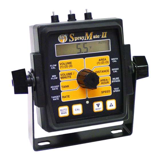
Page 18: Spraymate Tm Ii Console Functions
SprayMate II Console Func tions The SprayMate II II features a large, easy-to-read liquid crystal display, easy-to-use rotary dial and lighted panel for night use. VOLUME (1) (2) (3): AREA (1) (2) (3): Displays total gallons (liters) or lbs. (kg) Keeps a running count of the total acres of NH3 applied. -
Page 19: Calibration
Calibration English or Metric? The SprayMate II is capable of displaying in for ma tion in Illustration 13 Amer i can En glish or standard Metric measurement. The SprayMate II is shipped from the factory programmed for English. Note that the following procedures will also pray load factory default calibration values. -
Page 20: Entering Calibration Values
FLOW CAL: Calibration This po si tion is used to cal i brate the flow- (cont.) me ter for ac cu rate liquid mea sure ment. Every flowmeter Entering Calibration Values calibrated with VOLUME water at the factory FLOW (1) (2) (3) To enter or change any of the system’s calibration values, and assigned a “FLOW you must enter calibration mode. -
Page 21: Radar Or Gps Speed Sensor Calibration
Calibration (cont.) Entering Calibration Values Determining the SPEED CAL SPEED CAL: This position is used to calibrate the speed Illustration 15 sensor ac cu rate speed and dis tance SPEED DISTANCE measurement. When pray ™ this position is selected, the display will show CALHOLD THE SPEED CAL value. -
Page 22: Factory-Loaded Calibration Values
When a typical Inline is used when the servo is in the line operating speed is entered, the SprayMate II II will respond as if going out to the booms; Bypass is used when you were actually driving that speed. -
Page 23: Special" Calibration
“Special” Calibration Entering Calibration Values The “Special” calibration mode is used to set up system parameters that rarely need to be changed or adjusted. To enter Special Cal, put the system in HOLD, turn the console OFF, press and hold both the AUTO/MAN button and CAL button while turning console ON. -
Page 24: Units
Use the “+” and “-” buttons to and 12 on display. NOTE: if using an old style set the level where the Warning LED starts flashing and the Micro-Trak® servo valve, (see illustration), set word “FILL” flashes on to 8 volts. -
Page 25: Operation
We also recommend completion of Pre- ™ Field System Checkout described on pages 32-33 prior to MANAUTO beginning any field operations. 1 2 3 The SprayMate II II system can be operated in either Manual VOLUME AREA WIDTH FLOW... -
Page 26: Rotary Switches & Buttons
When the SprayMate are active during normal operation are the TAN boxes. II is used in conjunction with a Micro-Trak® NH3 control kit, Calibration positions are identified by the WHITE labeling on the console display will read total pounds (kg) of NH3 applied each side of the rotary selector (Please refer to Calibration since the counter was last reset. -
Page 27: Resetting System Counters
Operation (cont.) Resetting System Counters The AREA, DISTANCE and VOLUME counters maintain a running count during operation regardless of the position pray ate II ™ of the rotary switch. When any of these counters reach their MANAUTO maximum capacity, or when you want to start a new count, CALHOLD 1 2 3 4 5 the value may be reset to zero by performing the following... -
Page 28: Clearing System Counters
Operation (cont.) Clearing System Counters When the desired counter number is displayed, press the After the “-” (RESET) button has been held for 3 seconds, “-” (RESET) button and “CLEAr” will be displayed. the “CLEAr” message will be replaced by 0.0, indicating that counter pair #3 has been cleared. -
Page 29: Pre-Field Sys Tem Checkout Bypass Servo
Pre-Field Sys tem Checkout Bypass Servo Before beginning actual spraying, perform the following CAN’T GET THERE? If you can’t get to the desired “Pre-Field” procedure to ensure that your valve settings, ap pli ca tion rate, you may need different nozzles, pump, nozzle selection and desired speed range will allow the or you may need to make modifications to your plumbing SprayMate... -
Page 30: Pre-Field Sys Tem Checkout Inline Servo
Pre-Field Sys tem Checkout Inline Servo Before beginning actual spraying, perform the following CAN’T GET THERE? If you can’t get to the desired “Pre-Field” procedure to ensure that your valve settings, ap pli ca tion rate, you may need different nozzles, pump, nozzle selection and desired speed range will allow the or you may need to make modifications to your plumbing SprayMate... -
Page 31: Troubleshooting
Troubleshooting Messages/Warnings Typically indicates that defaults were entered by powering up with the CAL and “-” buttons held, but calibration mode was not entered and exited. Cycling power will not clear the bad CAL message, it can only cleared by entering and exiting calibration mode. -
Page 32: General
CONSOLE. Your system is protected by a warranty, and position. If the meter has been used for some time, wear Micro-Trak® will gladly correct any defect. may have changed the Flow Cal value. See Fine-Tuning Flowmeter Calibration in Appendix C. -
Page 33: Checking Individual Components
Troubleshooting (cont.) Checking Individual Components CONSOLE MAGNETIC HALL-EFFECT SPEED AND FLOW SENSORS The only way to field test a console is to con nect it to a Caution: Improper connection or voltage could damage the harness on a vehicle with a known working console or install Hall-effect sensor. -
Page 34: Checking Console Inputs
PLUMBING Proper plumbing is a very important factor in obtaining optimal performance from your SprayMate II II system. The Three-Pin Connector chart on the next page will help you determine what area of the plumbing may be causing your problem. -
Page 35: Plumbing Troubleshooting Charts
Plumbing Troubleshooting Chart SYMPTOM POSSIBLE CAUSE POSSIBLE SOLUTION Loses pressure in • Pump Air-lock • Clean strainer MANUAL • Larger hoses Little or no pressure • Too much restriction in servo loop • Larger hoses and fi ttings adjustment in MANUAL •... -
Page 36: Pump
Start with the handle screwed mostly out. Slowly bring pump up to operating RPM (make sure pressure does not go too high). Put the SprayMate II II in MAN and turn boom on. Hold adjust switch to “+” for about 30 seconds to fully close servo valve. -
Page 37: Appendices
Appendices... -
Page 38: Appendix A: Optional Speed Sensor Mounting Installation
Appendix A - Optional Speed Sensor Mounting Installation Implement Wheels Speed Sensor and Bracket 1. Secure magnets mechanically or with epoxy. 2. Rigidly mount sensor mounting bracket to the wheel assembly. Cut or bend “L” bracket as required for proper ¼”... -
Page 39: Mounting On Drive Shaft
• Secure sensor cable to frame with cable ties. Place first tie the shaft is turned. The magnets provided by Micro-Trak® are as close to sensor assembly as possible. marked with a punched dashed line on the SOUTH pole side of the magnet. -
Page 40: Appendix B: Fine Tuning Speed/Distance Calibration Valve
Appendix B Fine Tuning Speed/Distance Calibration Val ue (With Run/Hold Switch Kit Installed) This procedure is used to verify the calibration of systems With the rotary dial still at DISTANCE (SPEED CAL), press WITH the Run/Hold Switch Kit or an optional remote run/ and hold the “CAL”... -
Page 41: Fine Tuning Speed/Distance Calibration Value Without Run/Hold Kit
Appendix B (cont.) Fine Tuning Speed/Distance Calibration Val ue (Without Run/Hold Switch Kit Installed) This procedure is used to verify the calibration of systems With the rotary dial still at DISTANCE (SPEED CAL), WITHOUT run/hold switch kit installed. In order to achieve press and hold the “CAL”... -
Page 42: Appendix C: Fine Tuning Flowmeter Calibration Value
Appendix C Fine Tuning Flowmeter Calibration Value This procedure is used to verify and fine-tune the flowmeter the CAL icon. calibration. Every flowmeter is calibrated with water at the Momentarily press the CAL button. The CAL icon will factory and stamped with a calibration val ue. Enter that value begin to flash and the total volume will be displayed. -
Page 43: Appendix D: Flowmeter Assembly
Appendix D Flowmeter Assembly On a flat surface, place each housing half on end. Set and spin the turbine in each half. It should spin freely. If it does IMPORTANT: Opening the flowmeter will void the Flowmeter not spin freely, remove the turbine, wipe the shaft and try Calibration value assigned to your unit. -
Page 44: Appendix E: Radar Adapter Cables
Appendix E Radar Adapter Cables In-Cab John Deere Metri-Pack Connector RADAR CONNECTOR SIGNAL PIN 8000/9000 Series DICKEY-john Ground Signal Common DICKEY-john Cannon DICKEY-john Deutsch DICKEY-john Ford P/N 14810 DICKEY-john Packard In-Cab JD (8000 & 9000’s Metri-Pack Magnavox & Phillips Packard DICKEY-john Radar Amp Connector Raven Conxall... -
Page 45: Tm Ii Nh3 Specific
Appendix F SprayMate II NH3 Specific Wiring Harness Diagram... -
Page 46: Components Parts And Hardware
Before beginning installation, check the carton contents for the following items: Spray M ate II AUTOMATIC RATE CONTROLLER REFERENCE M A N U A L Power Cable SprayMate II II Console Owner’s Manual Console Mount Kit ™ P/N 14315 P/N 14869... -
Page 47: Appendix F Spraymate
Appendix F (cont.) SprayMate II NH3 Specific Single-Section System Diagram... -
Page 48: Speed Sensor Installation
Appendix F (cont.) SprayMate II NH3 Specific Speed Sensor Installation The speed sensor cable has a GREEN sensor body and mates INSTALLATION NOTE: The main harness provides two connection with the main harness cable having a YELLOW cable tie near points for the speed sensor. -
Page 49: Nh3 Kit Plumbing Installation
Appendix F (cont.) SprayMate II NH3 Specific NH3 Kit Plumbing Installation - Liquifier™, Liquifier Max™ & Liquifier Junior™ (NH3500) INSTALLATION: Remove any existing metering valves. If the old metering valve has a built-in manifold, it is recommended to install a separate new manifold for the Liquifier™... -
Page 50: Nh3 Kit Vapor Tube Installation
Appendix F (cont.) SprayMate II NH3 Specific NH3 Kit Vapor Tube Installation FOR ALL NH3 KITS IMPORTANT! Vapor tube plumbing MUST be connected to the Weld the steel vapor Liquifier™ vapor outlets for the system to work tubes to the back of correctly. -
Page 51: Console Functions
Appendix F (cont.) SprayMate II NH3 Specific SprayMate II Console Functions in NH3 Mode CAUTION: DO NOT attempt to calibrate the system while the nurse tank is connected to the system. To put the SprayMate II in NH3 mode, turn the console pray ate II ™... -
Page 52: Calibration Factors
Your Micro-Trak® NH3 flowmeter has been tested at the factory and assigned a “FLOW CAL” value (pulses/lb N) to make it operate properly with the SprayMate II II console. This number is stamped on the metal tag attached to the flowmeter. -
Page 53: Fine Tuning Flow Cal
Appendix F (cont.) SprayMate II NH3 Specific Fine Tuning Flowmeter Calibration Value for NH3 This procedure is used to verify and fine-tune the When the TOTAL FLOW value is displayed, use the “+” or flowmeter calibration. Every flowmeter is calibrated with “-”... -
Page 54: Field Operation
Appendix F (cont.) SprayMate II NH3 Specific Field Operation - Troubleshooting for NH3 In hilly or rough conditions the nurse tank dip tube will not Always follow accepted safety precautions. Make sure that remain submerged, allowing extra vapor in the system. This equipment is in good operating order. -
Page 55: Flowmeter Assemblies
Appendix F (cont.) SprayMate II NH3 Specific Flowmeter Assembly (FM-750 N) IMPORTANT: TO ASSEMBLE THE FLOWMETER Opening the flowmeter will void the Flow Calibration value assigned to your unit. However, you may Place the servo, flowmeter end up, in a vice or other suitable need to take the flowmeter apart for periodic cleaning or to fixture. - Page 56 Appendix F (cont.) SprayMate II NH3 Specific Flowmeter Assembly (FM-1500 N) IMPORTANT: After assembly, shaking flowmeter end-to-end should Opening the flowmeter will void the Flow produce a “rattling” sound (shaft end play). Blowing into Calibration value assigned to your unit. However, you may the meter from either end should cause the turbine to spin need to take the flowmeter apart for periodic cleaning or to freely.
-
Page 57: Tm Ii
INSTALLATION STEPS 3. Connect Module to Controller 1. Install Module IMPORTANT! Micro-Trak Controller MUST be set to “BYPASS” . Remove the backing from the Dual-Lock TM fasteners and attach to the bottom of the EMD unit. Position the EMD •... - Page 58 40 Amp Standard Electric Motor Appendix G (cont.) Driver Instructions EMD MODULE STATUS INFORMATION CONTROL SIGNAL STATUS LEDS • Green LED lights when servo signal is present and increasing • Red LED lights when servo signal is present and decreasing LED STATUS INDICATOR CODES Light on steady Unit is turned on and operating normally...
-
Page 59: Appendix H: Conversion Chart
Appendix H Conversion Chart English to Metric Metric to English When You Know Multiple By To Find When You Know Multiple By To Find LINEAR MEASUREMENT LINEAR MEASUREMENT inches 25.4 millimeters millimeters .039 inches feet 0.305 meters meters 3.28 feet yards 0.914 meters... -
Page 60: Appendix I: Replacement Parts List
5-foot Hall-effect Speed/Flow Sensor Cable with threaded sensor, nut and female connector 13226 5-foot remote run/hold sensor cable 01531 Speed sensor kit 01535 Remote run/hold sensor kit 14928 1” Micro-Trak® electric servo valve (liquid) 11501 FM750 GFN Flowmeter 10131 FM750 SS Flowmeter 14315 Power cable 14313... -
Page 61: Micro-Trak® Warranty
* Some limitations apply. See warranty statement for details. At Micro-Trak® Systems, we believe a product that delivers quality and performance at a low cost is what is needed to help today’s operator and the operator of the future compete in the world mar ket. - Page 62 M a n u f a c t u r e d i n U . S . A . b y : 111 East LeRay Ave., Box 99, Eagle Lake, MN 56024-0099 Toll-Free: 800-328-9613 507-257-3600 • Fax 507-257-3001 www.micro-trak.com • email: trakmail@micro-trak.com Printed in U.S.A. Copyright © 2017 Micro-Trak® Systems, Inc. • P/N 14943 • 041218...
Need help?
Do you have a question about the SprayMate II and is the answer not in the manual?
Questions and answers