Table of Contents
Advertisement
Quick Links
Advertisement
Table of Contents
Troubleshooting

Related Manuals for micro-trak MT-9000 Series


Summary of Contents for micro-trak MT-9000 Series
- Page 1 MT-9000 Automatic Spray Rate Controller Reference Manual for Liquid...
- Page 2 Dry Rate Control System Reference Manual The MT-9000 Series is an electronic monitor and control system that can help you achieve maximum yields and operate more cost-effectively by providing the information you need to maintain proper application rates of liquid, anhydrous ammonia and dry material.
-
Page 3: Warranty
Registration card information is for internal use only. * Some limitations apply. See warranty statement for details. At Micro-Trak Systems, we believe a product that delivers quality and performance at a low cost is what is needed to help today’s operator and the operator of the future. -
Page 4: Table Of Contents
Table of Contents Warranty...................................... 3 Table of Contents ...................................4-5 Introduction ....................................6 Component Parts and Assembly Hardware ........................7-8 Installation .....................................9-18 Required Tools ......................................9 Mounting the Display Console ................................9 Electrical Installation ....................................9 Speed Sensor Installation ................................10-11 Magnets ......................................10 Attaching Magnets ..................................11 Connecting the Speed Sensor Cable ............................... -
Page 5: Table Of Contents
Table of Contents (cont) Operation .................................... 32-34 Display Area, Power Switch, Auto/Man/Hold Switch, “+/- Switch, Boom Switches, Rate Buttons ......32 Tank Button, Alarm Switch, Test Button, Reset Button, DB-9 Connector ................33 Rotary Dial ........................................33 Warning Device, Light Sensor, Variable Rate Technology ....................... 34 Version/Hour Display on Startup ............................... -
Page 6: Introduction
Introduction Your new MT-9000 system is a high-performance controller, ALARM WITH EASY SET UP AND CONTROL designed for superior control of agricultural product An internal alarm is provided to alert the operator to error applications while providing easy-to-use features to help you conditions. -
Page 7: Component Parts And Assembly Hardware
MT-9000 Automatic Spray Rate Controller 14” Nylon Cable Ties P/N 12910 Reference Manual for Liquid Reference Manual MT-9000 Series Console Console Mount Kit P/N 13255 P/N 14354 P/N 13254 10’ Flow, Servo, Pressure, 10’ 10-Pin M/P 10’ Power/Boom Cable Kit... - Page 8 Component Parts and Assembly Hardware OPTIONAL Equipment 5’ 3-Pin W/P Extension Cable, comes with Servo Kit 5’ Hall-effect Flow Sensor P/N 10450 M-T 1” Electric Cable with threaded sensor, Run/Hold Adapter, Bulkhead Servo Valve comes with Flowmeter Kit P/N 14793 P/N 14928 P/N 13096 Vansco Radar...
-
Page 9: Installation
See Il lus tra tion 2. Be sure there is good metal-to-metal con- tact. Your MT-9000 Series is equipped with an elec tronic mem o ry which does not re quire a con stant supply of pow er to re tain daily totals or calibration val ues. -
Page 10: Speed Sensor Installation
• Mounting “L” bracket • Magnets • Cable ties Magnets The magnets provided by Micro-Trak are marked with a punched dashed line on the SOUTH pole side of the magnet. Please read the following information about magnet See Illustration 3A. -
Page 11: Attaching Magnets
SkyTrak or Dickey-John Vansco Radar Speed Sensor GPS speed sensors. An adapter cable may be required. Contact a Micro-Trak sales representative for de tails on any of these products, or call Mi cro-Trak Systems, Inc. at 1-800-328-9613. -
Page 12: Remote Run/Hold
10-pin connector on the back of the Run, Switch CLOSED = Hold. console. NOTE: If using the Micro-Trak Hall-Effect Run/Hold Sensor, order the #01535 Sensor Kit PLUS a #14793 Adapter Cable. (See Illustration below.) -
Page 13: Mounting And Plumbing Flowmeter
Installation (cont) Illustration 5 Mounting and Plumbing Flowmeter Hose Clamps* Sprayer Line* ¾” NPT Male Fitting* The flowmeter must be installed at the pump output after any strainers, return lines, or valves. Securely mount flowmeter Flowmeter Hose Clamps* (hardware not supplied) in a vertical position in an area away Sensor from intense vibration. -
Page 14: Range Adjust Valve
Installation Range (cont) Illustration 8 Adjust Valve Range Adjust Valve Tee “C” With oversized pumps, it may be necessary to install a range adjust valve. The range adjust valve will reduce the pumps output to the rest of the system. Adjustment of this valve is covered in the Pre-Field Checkout on page 31. -
Page 15: Electric Relief Valve
Installation (cont) Illustration 11 Electric Relief Valve Whenever all the boom control switches are turned off, or when HOLD is selected, the electric relief valve should be open. DO NOT install the relief valve closer than 12” to Servo the flowmeter. With the relief valve installed, connect one Valve terminal to ground and connect the other terminal on the Relief Valve... -
Page 16: Plumbing Overview Diagram
Installation (cont) MT-9000 Series Plumbing Overview Diagram... -
Page 17: Valve Diagrams
Installation (cont) MT-9000 Series Plumbing Overview Diagram Range For Oversized Pumps Adjust Valve Tee “C” Tee “A” For Positive Displacement Pumps Pressure Relief Valve Tee “C” Tee “A” If Optional Relief Valve Kit is Used Servo Valve Relief Valve Tee “B”... -
Page 18: Wiring Diagram
Installation (cont) Wiring Diagram MT-9X/MT-3405F BULKHEAD CONSOLE 3-PIN M/P 150 SHROUD 10-PIN M/P 150 SHROUD 7-PIN MIXED SHROUD 3-PIN M/P 10-PIN M/P 150 TOWER 7-PIN MIXED TOWER 150 TOWER 10-PIN M/P 150 SHROUD 7-PIN MIXED TOWER 10-PIN M/P 150 TOWER 7-PIN MIXED SHROUD... -
Page 19: Console Functions
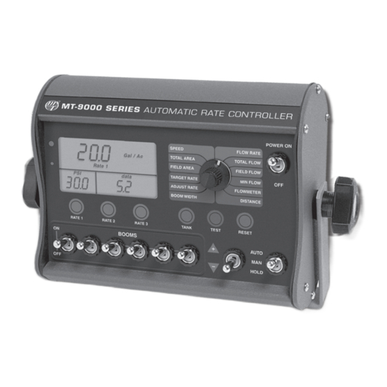
Console Functions - MT-9000 Series The MT-9000 Series features a large, easy-to-read display with bold, heavy duty buttons and toggle switches, and a rugged outer case. OPERATION POSITIONS RATE 1, 2, 3: When pressed, displays a preset application The MT-9000 Series offers two different Operation positions: rate. -
Page 20: Calibration
“Special” Calibration and go to Standard Liquid Calibration on pages 24-30. Entering “Special” Calibration Values Illustration 12 The MT-9000 Series has a number of control functions which are preset at the factory (See Factory Calibration Chart on MT-9000 SERIES AUTOMATIC RATE CONTROLLER page 24). -
Page 21: Units Of Measure, Material Type
“Special” Calibration (cont) Entering “Special” Calibration Values UNITS OF MEASURE: This “Special Cal” position is used to Display will Read select the units of measure meters data inches Gal / 1000 for the system. The units Lbs N / Ac Dial Position of measure determine how Gal / Ac... -
Page 22: Servo Type, Servo Polarity, Tank Alarm Set Point, Tank Size
“IL” for inline installations. DISTANCE NOTE: When the system is used in conjunction with a Micro-Trak NH3 control panel, always select “BP” for the servo valve polarity. TANK ALARM SET POINT: This “Special Cal” position Display will Read... -
Page 23: Hidden" Special Calibration
“Special” Calibration (cont) “Hidden” Special Calibration Parameters Servo Valve Control There are two “hidden” parameters which are used to make SERVO RESPONSE THRESHOLD adjustments to control the behavior of the Servo valve. See Determines what type of “response” time is used to make Appendix F in the back of this manual for more details. -
Page 24: Entering Calibration Values
Standard Liquid Calibration Illustration 13 Entering Standard Calibration MT-9000 SERIES AUTOMATIC RATE CONTROLLER Once in calibration mode, you may change any one, all or none of the values, in any order. To enter calibration mode, POWER ON Gal / 1000... -
Page 25: Boom Width, Setting Individual Boom Width, Banding Application Calibration
Illustration 14 value. Your Micro-Trak flowmeter has been tested at the factory and assigned a “Flowmeter” calibration value to make it operate properly with the MT-9000 Series console. This number is stamped on the metal tag attached to the flowmeter. See Illustration 14. -
Page 26: Min Flow And Pressure
Standard Liquid Calibration (cont) Entering Standard Calibration Values (cont) MIN FLOW AND PRESSURE: The purpose of this calibration MIN FLOW Display will Read parameter is to set the minimum recommended flow rate for the spray boom and the minimum recommended Gal / 1000 pressure for the nozzles. -
Page 27: Distance (Circ)
Standard Liquid Calibration (cont) Entering Standard Calibration Values (cont) DISTANCE: This position is used to calibrate the speed sensor for accurate speed, distance and area measurement. When Display will Read this position is selected, the display will show Distance Gal / 1000 the wheel circumference value and the Lbs N / Ac Traveled... -
Page 28: Fine-Tuning Speed/Distance Calibration
0 (approximately three seconds). Illustration 15 You are now ready to drive the measured course. Pick MT-9000 SERIES AUTOMATIC RATE CONTROLLER a location on the vehicle to use as a marker for starting and stopping the distance counting function (e.g. door handle, mirror, step). -
Page 29: Fine-Tuning Flowmeter Calibration
Turn off booms by placing the Master Switch in Illustration 16 HOLD, but leave pump running. Turn the rotary dial to the FLOWMETER position. Press MT-9000 SERIES AUTOMATIC RATE CONTROLLER and hold the RESET button until the display reads 0 (about three seconds). -
Page 30: Standard Factory-Loaded Calibration
Test speed is a built-in ground speed simulator that is used in performing pre-field checks. When a typical operating speed is entered, the MT-9000 Series will respond as if you were actually driving that speed. It allows you to simulate... -
Page 31: Pre-Field System Checkout
If the throttle valve is more than two-thirds closed, MT-9000 Series to provide the required application control. install range valve and perform pre-field again. This procedure should be repeated for each new nozzle Now is a good time to confirm that GPA, GPM, MPH, WIDTH selection and/or application rate. -
Page 32: Operation
MAN is flushing the system at the end of the day or with different nozzle installations, you could pre-program spraying season. the MT-9000 Series for each specific nozzle body. This will Using the “+/-” switch while in MAN allows the operator to en changing nozzles for each specific save time wh increase or decrease the flow or pressure as needed. -
Page 33: Tank Button, Alarm Switch, Test Button, Reset Button, Db-9 Connector
SPEED AUDIBLE ALARM Displays the ground speed in miles (kilometers) per hour. The MT-9000 Series consoles have an audible alarm that will FLOW RATE sound when the application rate exceeds “+/-” 10% of the Displays the actual volume per minute being applied. -
Page 34: Warning Device, Light Sensor, Variable Rate Technology
Version/Hour Display on Start-up MT-9000 SERIES MT-9000 SERIES AUTOMATIC RATE CONTROLLER On start-up, the MT-9000 Series console briefly (approximately three seconds) allows the operator to view the amount of POWER ON Gal / 1000 FLOW RATE SPEED... -
Page 35: Troubleshooting
If you have a two-way radio, it may be mounted too close to AREA COUNT IS INACCURATE the console. Keep all MT-9000 Series cables away from the Implement width or wheel circumference was measured radio, its antenna and power cable. -
Page 36: Checking Individual Components
TroubleShooting (cont) Checking Individual Components CONSOLE VANSCO RADAR SPEED SENSOR/ASTRO GPS SPEED The only way to field test a console is to connect it to a SENSOR harness on a vehicle with a known working console or install Carefully check your installation and operating instructions. it on an E-POP (Electronic Point-of-Purchase) display stand. -
Page 37: Checking Console Inputs
Troubleshooting (cont) Checking Console Inputs FLOWMETER: If there is no response from any of the following tests, refer to the main wiring diagram on the page 18 to locate the next Shaking the flowmeter end to end should produce a “rattling” connector in line toward the console and repeat the test at sound (shaft end play). -
Page 38: Plumbing Troubleshooting Chart
PRESSURE SENSOR Proper plumbing is a very important factor in obtaining optimal performance from your MT-9000 Series system. The The only way to field test the pressure sensor is to connect chart on the following page will help you determine what it to a known working console, apply pressure and verify the area of the plumbing may be causing your problem. -
Page 39: Plumbing Guidelines
Troubleshooting (cont) Plumbing Guidelines GENERAL PUMP In order for your sprayer to function properly, it must be The pump must have enough capacity to satisfy the agitation, correctly plumbed. This section will explain the purpose servo and flowmeter sections of the plumbing. To determine of each component, list some problems it can cause and if your pump is large enough you must add up the gallons recommend some possible solutions to those problems. - Page 40 Troubleshooting (cont) Plumbing Guidelines Valve Purpose and Adjustments RANGE ADJUST VALVE The range adjust valve is required when the pump is much TANK SHUT-OFF VALVE larger than necessary. When the range valve is opened, some The tank shut-off is for convenience only. It allows you to of the liquid will be bypassed around the pump to avoid work on the plumbing without draining the tank.
-
Page 41: Flowmeter Cleaning And Assembly
Troubleshooting (cont) Flowmeter Cleaning and Assembly IMPORTANT: Opening the flowmeter will void the Flow NOTE: The turbines have magnets built into the fins. There Calibration value assigned to your unit. However, you may are no visible magnets. need to take the flowmeter apart for periodic cleaning or On a flat surface, place each housing half on end. -
Page 42: Appendices
Appendices... -
Page 43: Appendix A: Optional Speed Sensor Mounting Installation
Appendix A Speed Sensor and Bracket Optional Speed Sensor Installation Implement Wheels ¼” Bolts, Lockwashers Secure magnets mechanically or with epoxy. and Nuts Rigidly mount sensor mounting bracket to the wheel Speed Sensor assembly. Cut or bend “L” bracket as required for proper positioning of sensor. - Page 44 Hall-effect speed sen sor must alternate as sensor into large hole selected on mount ing brack et. the shaft is turned. The magnets provided by Micro-Trak are Turn on remaining locking nut. Set sensor to proper marked with a punched dashed line on the SOUTH pole side distance from magnets (1/4”...
-
Page 45: Appendix B: Various Ball Valve Configurations
Appendix B Various Ball Valve Configurations Some basic 2, 3 & 4-wire configurations are shown at right. If you need assistance for wiring other than shown, contact Micro-Trak for wiring instructions. Switching Wire Relay + 12-volts Valve Relay – Valve Switching Wire Motor –... -
Page 46: Appendix C: Wiring Diagram For Non-Bulkhead System
Appendix C Wiring Diagram for NON-Bulkhead MT-9000 Systems MT 9000 SERIES CONSOLE 3-PIN METRI-PAK630 10-PIN METRI-PACK TOWER 10-PIN METRI-PACK TOWER SHROUD 10-PIN METRI-PACK SHROUD 10-PIN METRI-PACK TOWER 10-PIN METRI-PACK SHROUD 3-PIN 10-PIN METRI-PACK SHROUD METRI-PAK630 TOWER 10-PIN METRI-PACK TOWER 10-PIN METRI-PACK SHROUD 10-PIN METRI-PACK TOWER 10-PIN METRI-PACK SHROUD 10-PIN METRI-PACK TOWER... -
Page 47: Appendix D Conversion Chart
Appendix D Conversion Chart English to Metric Metric to English When You Know Multiple By To Find When You Know Multiple By To Find LINEAR MEASUREMENT LINEAR MEASUREMENT inches 25.4 millimeters millimeters .039 inches feet 0.305 meters meters 3.28 feet yards 0.914 meters... -
Page 48: Appendix E. Replacement Parts
Appendix E Replacement Parts List The following replacement parts are available from your dealer or distributor, or directly from: Micro-Trak Systems, Inc. P.O. Box 99, 111 East LeRay Avenue Eagle Lake, MN 56024-0099 When ordering parts, please list the model number of your console and the description and part number of each part that you want to order. -
Page 49: Appendix F: Servo Valve Control Adjust Parameters
Appendix F Servo Valve Control Adjust Parameters SERVO RESPONSE THRESHOLD Typically the user should not need to make adjustments, as the factory default settings are optimized, but in some Determines what type of response time is used to make the installations (assuming plumbing and operating range are Servo valve react to changes in flow. -
Page 50: Appendix G: Using An External Pc To Control The Mt-9000
Appendix G Using an External PC to Control the MT-9000 NOTE: While in any form of “override” the console will An external computer (PC or Pocket PC) running a Variable Rate Application (VRA) program can be used to remotely continue to receive and store any new VRA Targets sent control the MT-9000. -
Page 51: Glossary Of Terms
A shaft that transfers power from one place STANDARD CALIBRATION: A calibration mode of the to another. MT-9000 Series which lets the operator enter values specific FLOW-BASED CONTROL: Using information from a to their operating needs. flowmeter to determine the amount of adjustment required. - Page 52 MANUFACTURED IN THE U.S.A. BY 1305 Stadium Road, Mankato, MN 56001-5355 Toll Free: (800) 328-9613 • (507) 257-3600 www.micro-trak.com • trakmail@micro-trak.com © 2000 • Micro-Trak Systems, Inc. • Printed in U.S.A. • P/N 13255 Rev 7...
Need help?
Do you have a question about the MT-9000 Series and is the answer not in the manual?
Questions and answers