Table of Contents
Advertisement
Quick Links
Advertisement
Table of Contents
Troubleshooting

Related Manuals for micro-trak SprayMate II


Summary of Contents for micro-trak SprayMate II
- Page 1 pray ™ AUTOMATIC RATE CONTROLLER REFERENCE M A N U A L...
- Page 2 This manual is written for the SprayMate II, which may be used for either English, Metric or Turf measurement. Please read the manual carefully and follow the instructions as they apply to your usage.
-
Page 3: Micro-Trak Warranty
* Some limitations apply. See warranty statement for details. At Micro-Trak Systems, we believe a product that delivers quality and performance at a low cost is what is needed to help today’s operator and the operator of the future compete in the world market. -
Page 4: Table Of Contents
Component Parts and Assembly Hardware ..............................5-6 Installation............................................7-10 Mounting the display console, switch box, and run/hold switch kit ..........................7 SprayMate II System Overview with ignition switch hookup ............................8 SprayMate II System Overview with optional power switch ............................9 SprayMate II Wiring Overview ........................................10 Electrical Installation ............................................11... -
Page 5: Table Of Contents
Without Run/Hold Switch Kit Installed..................................47 Appendix C: Fine Tuning Flowmeter Calibration Value..............................48 Appendix D: Flowmeter Assembly ......................................49 Appendix E: Radar Adapter Cables ......................................50 Appendix F: SprayMate II Wiring Diagram ....................................51 Appendix G: SprayMate II NH3 SPECIFIC..................................52-67 Wiring Diagram ............................................52 System Layout for NH3........................................53 Component Parts, Assembly ......................................54-55... -
Page 6: Component Parts And Assembly Hardware
Component Parts and Assembly Hardware Before beginning installation, check the carton contents for the following items: 5' Hall-effect Flow Sensor Cable with threaded sensor Owner’s Manual SprayMate ™ II Console P/N 13096 P/N 14943 P/N 14869 M-T 1” Electric Servo Valve P/N 14928 FM750 GFN (P/N 11501) Flowmeter... - Page 7 Component Parts and Assembly Hardware (Continued) Boom/ Servo/Flow Harness P/N 14313 Power Cable P/N 14315 14” Nylon cable ties (10) P/N 12910 72" ignition cable 120" 10-pin extension cable P/N 14314 P/N 14316 Optional Kit, Power Switch P/N 14360 Kit, Run/Hold Switch P/N 14361...
-
Page 8: Installation
Putting It All Together Installation Illustration 1A Bolts Mounting the Display Console Drill 1/4" (7 mm) holes for bolts, or 3/16" (5mm) Select a mounting location which seems most workable, and holes for self- that best fits your needs. It should be convenient to reach and tapping screws. -
Page 9: Spraymate Ii System Overview With Ignition Switch Hookup
SprayMate II System Overview (with ignition switch hookup) -
Page 10: Spraymate Ii System Overview With Optional Power Switch
SprayMate II System Overview (with optional Power switch) -
Page 11: Spraymate Ii Wiring Overview
SprayMate II Wiring Overview SprayMate II Console... -
Page 12: Electrical Installation
Electrical Installation This section explains how to connect your SprayMate II to a 12- ON/OFF SWITCH CONNECTION volt power source, and how to connect your boom shut-off The SprayMate II system includes a provision for either using a valves. switched (ignition) source or an optional power switch to turn the system on. -
Page 13: Spraymate Ii Boom Connections
ONLY. Tie back and tape off to avoid shorting (if not used). 120 in 120 in Boom 1 Boom 2 Boom 3 Aux. 12V Illustration 4B Ground (BLACK) If using 2-wire ball valves, contact a Micro-Trak representative for assistance. Monitor Special Boom Wire ball valve +12V (WHITE) -
Page 14: Speed Sensor Installation
Magnets Please read the following information about magnet spacing and The magnets provided by Micro-Trak are marked with a polarity. punched dashed line on the SOUTH pole side of the magnet. See Illustration 5A. - Page 15 Sensor assembly must not wheel or drive shaft begins turning, a speed impulse is sent to be mounted more than the SprayMate II console every time a magnet passes by the tip 45˚ from perpendicular Bracket must be of the speed sensor. For the speed sensor to operate properly,...
-
Page 16: Connecting The Speed Sensor Cable
Green Yellow Flow Green Green with the GREEN tie. See SprayMate II Wiring Diagram on page 10. Run/Hold Black Grey The optional Run/hold sensor also uses the same type of connector as the speed and flow sensors. However, the Run/hold... -
Page 17: Spraymate Ii Plumbing Overview (Bypass)
SprayMate II Plumbing Overview Bypass Configuration... -
Page 18: Spraymate Ii Plumbing Overview (Inline)
SprayMate II Plumbing Overview In-Line Configuration... -
Page 19: Mounting And Plumbing Flowmeter
Main Harness into place. Secure cable with ties provided. See Illustration 8 and flow connector Flow sensor SprayMate II Wiring Diagram on page 10. cable connector GREEN tie Note: Sensors with GREEN bodies can be used for either SPEED or FLOW but not for RUN/HOLD. -
Page 20: Remote Run/Hold
North Sensor (Black body) Care and Maintenance of your SprayMate II Console Store the console in a cool dry location if it will not be used for an extended period of time, such as during the off- season. As with any electronic equipment, use care in cleaning so that water or other liquids do not enter the case. -
Page 21: Manual Pressure Relief Valve
If more length is required, use a 3-pin W/P Servo extension cable of the appropriate length. IMPORTANT NOTE: If using the SprayMate II with an old -style Micro-Trak servo valve, the valve voltage must be set to 8 volts. See Special Calibration Valve Voltage section on page 28. -
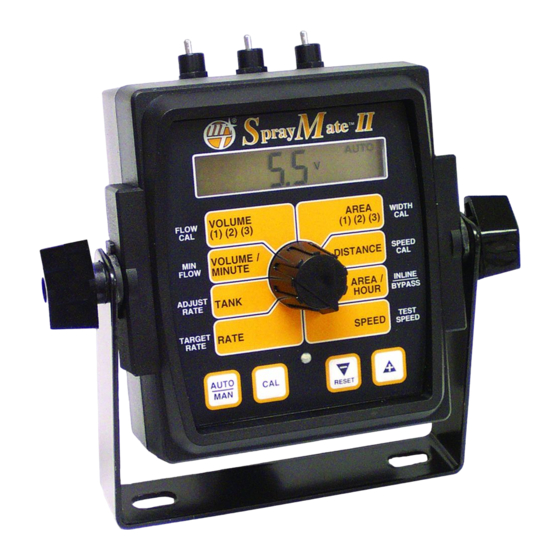
Page 22: Spraymate Ii Console Functions
SprayMate Console Functions The SprayMate II features a large, easy-to-read liquid crystal display, easy-to-use rotary dial and lighted panel for night use. VOLUME (1) (2) (3) : Displays total gallons (liters) or lbs. AREA (1) (2) (3): Keeps a running count of the total acres (kg) of NH3 applied. -
Page 23: Calibration
Calibration English or Metric? Illustration 13 The SprayMate II is capable of displaying information in Ameri- can English or standard Metric measurement. The SprayMate II pray is shipped from the factory programmed for English. Note that ™ the following procedures will also load factory default MANAUTO calibration values. -
Page 24: Entering Calibration Values
Entering Calibration Values: To enter or change any of the system’s calibration values, you INLINE/BYPASS: The display will show InLinE or bYPASS. must enter calibration mode. To enter calibration mode, STOP Use the "+" or "-" buttons the vehicle, turn all booms OFF or put the console in HOLD and to toggle to desired press and hold the CAL button until the "CAL"... -
Page 25: Special Cal For Radar Or Gps
SPEED CAL: This position is used to calibrate the speed Illustration 15 sensor for accurate speed and distance measurement. When this position is selected, the display will show THE SPEED CAL value. The SPEED value pray SPEED DISTANCE number shown along ™... -
Page 26: Determining Wheel Circumference
Determining the SPEED CAL (Skip this section if using radar or GPS speed sensor) For the console to calculate the correct speed and measure Illustration 16 distance accurately, the circumference of the sensor-equipped wheel must be entered. Determine the circumference of the sensor-mounted wheel to the nearest tenth of an inch (tenth of a centimeter) with the following method: METHOD:... -
Page 27: Factory-Loaded Calibration Values
Every flowmeter is calibrated FLOW typical operating speed is (1) (2) (3) with water at the factory and entered, the SprayMate II assigned a “FLOW CAL” will respond as if you were value to make it operate actually driving that speed. It... -
Page 28: "Special" Calibration
"Special" Calibration The "Special" calibration mode is used to set up system parameters that rarely need to be changed or adjusted. To enter Special Cal, put the system in HOLD, turn the console OFF, press and hold both the AUTO/MAN button and CAL button while turning console ON. -
Page 29: Units
8 Tank Alarm Set Point: and 12 on display. NOTE: if Use the "+" and "-" using an old style Micro-Trak VOLUME / buttons to set the level servo valve, (see illustration), set to 8 volts. -
Page 30: Operation
System Checkout described on pages 33-34 prior to beginning any ™ field operations. MANAUTO The SprayMate II system can be operated in either Manual or 1 2 3 Automatic mode. In manual mode, the application rate (GPA or VOLUME AREA... - Page 31 VOLUME: Displays the total gallons (liters) applied since the active counter was last reset to zero. When the SprayMate II is used in conjunction with a Micro-Trak NH3 control kit, the console display will read total pounds (kg) of NH3 applied since the counter was last reset.To select a pair of AREA and VOLUME...
-
Page 32: Resetting System Counters
Resetting System Counters The AREA, DISTANCE and VOLUME counters maintain a running pray ate II count during operation regardless of the position of the rotary ™ switch. When any of these counters reach their maximum MANAUTO capacity, or when you want to start a new count, the value may CALHOLD 1 2 3 4 5 be reset to zero by performing the following routine. - Page 33 To clear counters: When the desired counter number is displayed, press the "-" (RESET) button and "CLEAr" will be displayed. NOTE: holding the "-" (RESET) button for 2 seconds will clear both the #3 AREA After the "-" (RESET) button has been counter and the #3 VOLUME counter whether the rotary switch held for 3 seconds, the "CLEAr"...
-
Page 34: Prefield System Checkout - Bypass Servo
Please refer to Troubleshooting Plumbing on page 39. selection and desired speed range will allow the SprayMate II to Adjust agitation valve for desired agitation. If range valve is provide the required application control.This procedure should... -
Page 35: Prefield System Checkout - Inline Servo
SprayMate II to need to make modifications to your plumbing configuration. provide the required application control.This procedure should Please refer to Troubleshooting Plumbing on page 39. -
Page 36: Troubleshooting
Troubleshooting Messages / Warnings Typically indicates that defaults were entered by powering up with the CAL and "-" buttons held, but calibration mode was not entered and exited. Cycling power will not clear the bad CAL message, it can only cleared by entering and exiting calibration mode. -
Page 37: Console Appears Dead
If you have a two-way radio, it may be mounted too close to alignment and spacing of speed sensor in relationship to magnet the console. Keep all SprayMate II cables away from the radio, assembly. Make sure magnet polarities are alternated. Also check its antenna and power cable. -
Page 38: Checking Individual Components
Troubleshooting continued Checking Individual Components MAGNETIC HALL-EFFECT SPEED AND FLOW SENSORS: Caution: Improper connection or voltage could damage the CONSOLE: Hall-effect sensor. The Hall-effect sensor works similar to a The only way to field test a console is to connect it to a harness reed switch, but requires power in order to function. -
Page 39: Console Inputs
PLUMBING: console should respond with some flow rate reading. Proper plumbing is a very important factor in obtaining optimal performance from your SprayMate II system.The chart on the next page will help you determine what area of the Illustration 18 plumbing may be causing your problem. -
Page 40: Plumbing Troubleshooting Chart
Plumbing Troubleshooting Chart SYMPTOM POSSIBLE CAUSE POSSIBLE SOLUTION Loses pressure in MAN Pump Airlock Clean strainer Larger hoses Little or no pressure Too much restriction Larger hoses and fittings adjustment in MAN in servo loop No sharp bends Pressure won’t go high Pump starved or too small Larger hoses enough in MAN... -
Page 41: Plumbing Guidelines
Slowly bring pump up to operating RPM (make too small, you may experience little or no pressure adjustment. sure pressure does not go too high). Put the SprayMate II in MAN and turn boom on. Hold adjust switch to “+” for about 30 FLOWMETER seconds to fully close servo valve.Turn booms OFF. -
Page 42: Throttle Valve
Plumbing Guidelines (cont.) Throttle Valve The throttle valve limits your high end to maximize servo performance. Start with throttle valve fully open and perform the Prefield System Checkout on page 33-34. Example: With the throttle fully open and servo fully closed, you may be able to get 50 GPA at 5 MPH when you only want 25 GPA. -
Page 43: Appendices
Appendices... -
Page 44: Appendix A: Optional Speed Sensor Mounting Installation
Appendix A: Optional Speed Sensor Mounting Installation Implement Wheels Speed Sensor and Bracket 1. Secure magnets mechanically or with epoxy. 1/4" bolts, 2. Rigidly mount sensor mounting bracket to the wheel lockwashers assembly. Cut or bend “L” bracket as required for proper and nuts positioning of sensor. -
Page 45: Atv Wheels
Appendix A: cont. ATV Wheels Two mounting examples are illustrated. Sensor Cut bracket 1. Using one cable tie (ribbed side toward magnets), secure two bracket to clear rim magnets to the wheel hub so they are exactly opposite each other. Alternate the magnets’ polarities. Magnet Axle 2. -
Page 46: Optional Speed Sensor Mounting On Drive Shaft
See SPEED CAL on page 25. ed by the Hall-effect speed sensor must alternate as the shaft is turned. The magnets provided by Micro-Trak are marked with a punched dashed line on the SOUTH pole side of the magnet. •... -
Page 47: Appendix B: Fine Tuning Speed/Distance Calibration Value
Appendix B: Fine Tuning Speed/Distance Calibration Value (With Run/Hold Switch Kit Installed) This procedure is used to verify the calibration of systems WITH the Momentarily press CAL and the word CAL will begin to flash Run/Hold Switch Kit or an optional remote run/hold kit installed. In and the distance travelled will be displayed. -
Page 48: Without Run/Hold Switch Kit Installed
Appendix B: cont. Fine Tuning Speed/Distance Calibration Value (Without Run/Hold Switch Kit Installed) This procedure is used to verify the calibration of systems WITHOUT press the “+” or “-” key to adjust the figure to match the dis- run/hold switch kit installed. In order to achieve accurate tance you actually drove.If the display reads too high, use the measurements, each step in this fine tuning procedure should be “-”... -
Page 49: Appendix C: Fine Tuning Flowmeter Calibration Value
Appendix C: Fine Tuning Flowmeter Calibration Value This procedure is used to verify and fine-tune the flowmeter 10. Exit calibration by holding the “CAL” button until the red calibration. Every flowmeter is calibrated with water at the warning light goes out (about one second). factory and stamped with a calibration value. -
Page 50: Appendix D: Flowmeter Assembly
Appendix D: Flowmeter Assembly IMPORTANT: freely, remove the turbine, wipe the shaft and try again. If is still Opening the flowmeter will void the Flowmeter does not spin freely, the shaft or bearings may have excessive Calibration value assigned to your unit. However, you may need to wear. -
Page 51: Appendix E: Radar Adapter Cables
Appendix E: Radar “Y” Adapter Cables In-Cab John Deere Metri-Pak Connector 8000/9000 Series RADAR CONNECTOR SIGNAL PIN Ground DICKEY-john Signal Common DICKEY-john Cannon DICKEY-john Deutsch DICKEY-john Ford DICKEY-john Packard In-Cab JD (8000 & 9000’s) Metri-Pak DICKEY-john Radar Amp Connector Magnavox & Phillips Packard Raven Conxall... -
Page 52: Appendix F: Spraymate Ii Wiring Diagram
Appendix F: SprayMate II Wiring Diagram... -
Page 53: Wiring Diagram
Appendix G: SprayMate II Wiring Diagram for NH3 Flow Signal System Power Flow Ground Speed Signal Speed Power Speed Ground Servo - Servo + Valve Power System Ground... -
Page 54: System Layout For Nh3
Appendix G: SprayMate II System Layout for NH3... -
Page 55: Component Parts, Assembly
Appendix G: SprayMate II - NH3 Specific Component Parts & Assembly Hardware Before beginning installation, check the carton contents for the following items: SprayMate ™ II Console P/N 14869 Owner’s Manual Console Mount Kit P/N 14943 P/N 13181 Power Cable... -
Page 56: Appendix G: Spraymate Ii Nh3 Specific
Appendix G: SprayMate II - NH3 Specific Component Parts for SprayMate II for NH3 Kits NH3500 Kit P/N 01120 The Liquifier ™ Kit P/N 01097... -
Page 57: Installation
Appendix G: SprayMate II - NH3 Specific Installation Mounting the Display Console See installation section at front of manual for installation of console, cables, speed, sensor, etc. The following sections describe installation of NH3-specific items only. Optional Mounting: Base Plate/Suction Cup... - Page 58 Appendix G: SprayMate II - NH3 Specific Installation continued Connecting the Speed Sensor Cable The speed sensor cable has a GREEN sensor body and mates with the two cables with YELLOW tie). Using this connection point will the main harness cable having a YELLOW cable tie near the 3-pin disable the connection point on the implement end of the main harness.
- Page 59 Appendix G: SprayMate II - NH3 Specific NH3500 Kit Installation NH3500 Kit Installation Remove any existing metering valves. If the old metering valve has a built-in manifold, it is recommended to install a separate new manifold for the NH3500 kit. Another option, although not...
- Page 60 Appendix G: SprayMate II - NH3 Specific Liquifier Installation Liquifier Installation PRE-INSTALLATION: Remove the Liquifier plumbing panel from strainer inlet. Check for proper hose length for operation of the the shipping board. The Liquifier plumbing panel has been disconnect mechanism of the breakaway coupler. Connect the packaged with the "strainer end"...
- Page 61 Appendix G: SprayMate II - NH3 Specific NH3500 Vapor Tube Installation NH3500 Vapor Tube Installation Locate the 1/2" EVA vapor hose supplied with the kit. Starting on one half of the tool bar, connect the 1/2" hose to the outside steel vapor tube.
-
Page 62: Console Functions
CAUTION: DO NOT attempt to calibrate the system while the nurse tank is connected to the system. To put the SprayMate II in NH3 mode, turn the console OFF, turn the shutoff valve off and select Special Calibration by pressing the AUTO/MAN and CAL buttons while turning console power on. -
Page 63: Calibration Factors
“FLOW CAL”value (pulses/lb N) to make it operate Target Rate when operating in properly with the SprayMate II console. This number is stamped AUTOmatic mode. Enter 0 on the metal tag attached to the flowmeter. See below. This is a to disable this feature. - Page 64 Appendix G: SprayMate II - NH3 Specific Calibration Factors for NH3 cont. INLINE/BYPASS: TEST SPEED: Not used for Set to BYPASS (harness reverses the wires so the servo will run anhydrous ammonia correctly). NOTE: if application. used on a Micro-Trak...
-
Page 65: Fine Tuning Flow Cal
Appendix G: SprayMate II - NH3 Specific Fine Tuning Flow Calibration Value - NH3 This procedure used verify fine-tune flowmeter calibration. Every flowmeter is calibrated with water at the factory and stamped with a calibration value. Enter that value as a starting point and use this procedure to fine-tune that value for your specific installation and NH3 application (please refer to Entering Flowmeter Calibration Value, page 26). -
Page 66: Field Operation
Appendix G: SprayMate II - NH3 Specific Field Operation - Troubleshooting for NH3 Field Operation: Always follow accepted safety precautions. Make sure that In hilly or rough conditions the nurse tank dip tube will not equipment is in good operating order. Before connecting the remain submerged, allowing extra vapor in the system. -
Page 67: Flowmeter Assemblies
Appendix G: SprayMate II - NH3 Specific Flowmeter Assembly (FM-750 N) housing so that the two square lugs are lined up with each IMPORTANT: Opening the flowmeter will void the Flow other.) Drop all three bolts into holes. Hold lock washers in place Calibration value assigned to your unit. - Page 68 Appendix G: SprayMate II - NH3 Specific Flowmeter Assembly (FM-1500 N) Opening the flowmeter will void the Flow IMPORTANT: After assembly, shaking flowmeter end-to-end should produce Calibration value assigned to your unit. However, you may need a "rattling" sound (shaft end play). Blowing into the meter from to take the flowmeter apart for periodic cleaning or to remove either end should cause the turbine to spin freely.
-
Page 69: Appendix H: Epd For Spraymate Ii
A ppendix H: EPD (Electric Pump Driver) for SprayMate II MATING CONNECTOR System diagram HOUSING (1) P/N 11132 SEALS (2) P/N 10399 TERMINALS (2) 10401... -
Page 70: Installation
This section explains how to connect your EPD to a 12-volt power plastic cable ties. source, and how to connect your EPD to your SprayMate II harness. Locate the servo cable. Connect the 3-pin W/P shroud to the 3- The EPD must be connected to a 12-volt DC negative ground pin W/P tower on the EPD module. -
Page 71: Appendix I: Conversion Chart
Appendix I: Conversion Chart English to Metric Linear 1 inch 2.54 centimeters Measurement 1 foot 30.48 centimeters or .305 meters 1 yard 0.914 meters 1 mile 1.609 kilometers 1 acre 0.405 hectares Land 1 square mile 2.59 square kilometers or 259 hectares Measurement 1 pint 0.473 liters... -
Page 72: Appendix J: Replacement Parts List
14313 Flow, servo, boom harness 14314 6-foot Ignition Cable 14311 SprayMate II NH3 Adapter Cable 14360 SprayMate II Power (On/Off ) Switch Kit 14361 SprayMate II Run/Hold Switch Kit 10899 FM750N Flowmeter - NH3 ONLY 14348 FM1500N Flowmeter - NH3/Liquifier... - Page 73 Notes...
- Page 74 Manufactured in U.S. A. by 111 East LeRay Ave., Box 99, Eagle Lake, MN 56024-0099 Toll-Free: 800-328-9613 507-257-3600 • Fax 507-257-3001 www.micro-trak.com • Email: trakmail@micro-trak.com Printed in U.S.A. Copyright 2006 P/N 14943 Rev. 4...
Need help?
Do you have a question about the SprayMate II and is the answer not in the manual?
Questions and answers