
Related Manuals for micro-trak DUAL CONTROL MT-3405D


Summary of Contents for micro-trak DUAL CONTROL MT-3405D
- Page 1 MT-3405D ™ “ D U A L C O N T R O L ” A U T O M A T I C R A T E C O N T R O L L E R R E F E R E N C E M A N U A L...
- Page 2 If you do encounter a problem that cannot be corrected by reviewing this manual, consult your dealer or distributor, or contact a Micro-Trak technician for assistance. Toll Free in U.S. or Canada: 800-328-9613 507-257-3600 www.micro-trak.com •...
- Page 3 * Some limitations apply. See warranty statement for details. At Micro-Trak Systems, we believe a product that delivers quality and performance at a low cost is what is needed to help today’s operator and the operator of the future compete in the world mar ket.
-
Page 4: Table Of Contents
Table of Contents Table of Contents ...................................4-5 Dual Loop Overview ................................6-8 Component Parts and Assembly Hardware plus Optional Equipment ..............9-10 MT-3405D System Layout with Liquid Branch on Loop 2 ....................11 MT-3405D Wiring with Liquid Branch on Loop 2 ......................12 MT-3405D System Layout with Layout with NH3 on Loop 2 .................. -
Page 5: Table Of Contents
Table of Contents (cont) Plumbing Guidelines ................................ 45-46 General .......................................45 Pump inlet ......................................45 Agitation ......................................45 Servo ........................................45 Flowmeter ......................................45 Pump ........................................45 Valve Purpose and Adjustments ............................... 45 Tank shut-off valve ..................................45 Agitation shut-off valve ................................45 Pressure relief valve ..................................45 Range adjust valve ..................................46 Throttle valve (Bypass Plumbing) ............................. - Page 6 RATE is off target or if above DATA display decrease application rates tank is low The MT-3405D system is designed to work with all optional subsystems provided by Micro-Trak ®: • NH3 kits • EPD kits (electric motor/pump driver modules) • Hydraulic drive kits •...
- Page 7 MT-3405D Dual Loop Controller Overview (cont) The MT-3405D is designed for flexibility and ease of use. Controller 2 (1 Boom Section) It can be configured in one of three primary operating modes: AUTO • NORMAL • INJECTION • PARALLEL 1. NORMAL MODE: APPLICATION RATE 2 Two separate controllers with separate booms.
- Page 8 MT-3405D Dual Loop Controller Overview (cont) 3. PARALLEL MODE: Two separate controllers with separate Boom Section Valves Controller 1 and shared (parallel) Boom On/Off control. Aux. Switch Controller 1 (5 Boom Sections) Controller 2 (5 Boom Sections) AUTO AUTO MASTER HOLD APPLICATION RATE 1 APPLICATION RATE 2...
- Page 9 Component Parts and Assembly Hardware Before beginning installation, check the carton contents for the following items: Console Mount Kit MT-3405D™ Console 14” Nylon Cable Ties Terminal Kit w/ Fuse Holder P/N 13774 P/N 17154 P/N 12910 (2) P/N 13270 MT-3405D ™...
- Page 10 Component Parts (Cont) Optional Equipment Speed Sensor Kit P/N 01531 Including items A-F, below: E. Magnets (6) A. 5’ Hall-effect Speed/Flow C. 15’ 3-Pin Extension Cable F. Hardware Bag P/N 12069 Sensor Cable P/N 13096 M/P 150 P/N 13207 P/N 13251 (2 in hardware bag) B.
-
Page 11: Mt-3405D System Layout With Liquid Branch On Loop 2
MT-3405D System Layout with Liquid Branch on Loop 2 Channel 1: Standard Liquid Harness Channel 2: Ch2 Liquid branch Harness... -
Page 12: Mt-3405D Wiring With Liquid Branch On Loop 2
MT-3405D Wiring with Liquid Branch on Loop 2... - Page 13 MT-3405D System Layout with NH3 on Loop 2 Channel 1: Standard Liquid Harness Channel 2: Standard NH3 Harness...
-
Page 14: Mt-3405D Wiring With Nh3 Branch On Loop 2
MT-3405D Wiring with NH3 Branch on Loop 2... - Page 15 MT-3405D System Layout - Bypass Configuration...
- Page 16 MT-3405D Layout - InLine Configuration...
-
Page 17: Installation
Installation Mounting the Display Console Tools Needed to Install the MT-3405D • Screwdrivers • Pliers Select a mounting location which seems most workable, and • Set of Wrenches • Wire Cutter that best fits your needs. It should be con ve nient to reach •... -
Page 18: Speed Sensor Installation
1. Non-driven wheel on tractor, vehicle or implement. This is less susceptible to errors resulting from wheel slip. Magnets The magnets provided by Micro-Trak are marked with a punched dashed line on the SOUTH pole side of the magnet. Please read the following information about magnet spacing See Illustration below. -
Page 19: Attaching The Speed Sensor
Astro Series or Other GPS Speed Sensor Interfaces The MT-3405D may also be used with most GPS speed sensors that output a pulsed signal, such as the Micro-Trak Astro II and 5, SkyTrak or Dickey-John GPS speed sensors. An adapter cable may be required. -
Page 20: Remote Run/Hold (Ch1 Only)
Connect to switch (not supplied) and connect other terminal of switch to ground. NOTE: If using the Micro-Trak Hall-Effect Run/Hold Sensor, When the switch is OPEN (Run), both channels can run using order the #01535 Sensor Kit PLUS a #14793 Adapter Cable. -
Page 21: Mounting And Plumbing Flowmeter
To avoid erratic flow readings allow a minimum of 6” of straight tubing at the flowmeter input and output. If installation constraints don’t allow this keep bends as gentle as possible. Micro-Trak flow meters are bidirectional Hose Clamp * (exception: green plastic turbine and mag flowmeters are “L”... -
Page 22: Manual Pressure Relief Valve
If more length is required, use a 3-pin W/P extension cable of the appropriate length. IMPORTANT NOTE: If using the MT-3405D with an old style Micro-Trak servo valve, the valve voltage must be set to 8 Flowmeter volts. See Special Calibration Valve Voltage section on page NOTE: The servo valve may be installed in the main spray line as shown in Illustration 10. -
Page 23: Electric Relief Valve (Ch1 Only)
Installation If your relief valve does not have flow-through port, you must (cont) add a “T” fitting. NOTE: To assure a good connection and Electric Relief Valve (Ch1 only) avoid corrosion, coat electrical connections with silicone grease. The relief valve is used to “dump” pressure when your boom valves are turned off. -
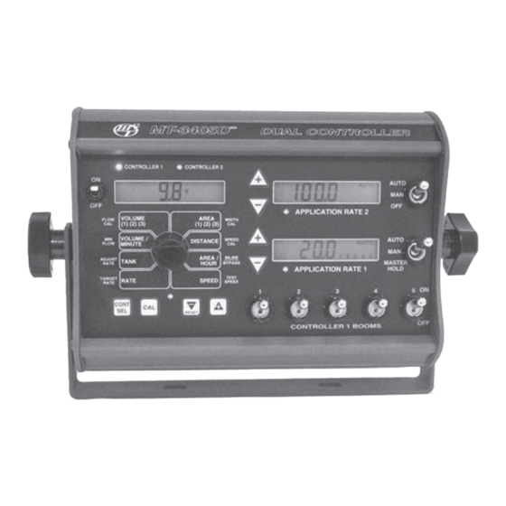
Page 24: Console Functions
Overview of MT-3405D Console Func tions The MT-3405D features three large, easy-to-read liquid crystal displays and a lighted panel for night use. The right-hand displays always show the application rates and the left-hand display shows data selected by the rotary switch and the controller selection as indicated by the yellow lights above the rotary switch. - Page 25 Overview of MT-3405D Console Func tions (cont) CONTROLLER 1 CONTROLLER 2 Controller 1 Booms AUTO/MAN/MASTER HOLD (Ch1): AUTO/MAN/OFF (Ch2): Selecting either the “AUTO” or “MAN” switch position turns Selecting either the “AUTO” or “MAN” switch position all active boom valves ON for Automatic or Manual control turns the single boom output ON for Automatic or Manual operation on Controller 1.
-
Page 26: Calibration
Calibration Loading Default Calibration Values English or Metric? CONTROLLER 1 CONTROLLER 2 AUTO The MT-3405D is capable of displaying in for ma tion in Amer i- MANAUTO CALHOLD can En glish or standard Metric measurement. The MT-3405D V 1 2 3 4 5 APPLICATION RATE 2 is shipped from the factory programmed for English. -
Page 27: Ch1/Ch2 Cal Selection
DO NOT enter the actual flow of your spray application. Your Micro-Trak flowmeter has been tested at the factory : If the min i mum flow rate for the nozzle you are and assigned a “FLOW CAL”... - Page 28 Bypass is used when the servo onto when operating in AUTO. is in a return line. NOTE: If used on a Micro-Trak NOTE: Either channel may be disabled by AREA / INLINE...
-
Page 29: Determining The Speed Cal
Calibration (cont) CONTROLLER 1 CONTROLLER 2 Entering Calibration Values AUTO (cont) MANAUTO CAL HOLD APPLICATION RATE 2 SPEED CAL: This position is used to calibrate the speed VOLUME AREA FLOW WIDTH (1) (2) (3) (1) (2) (3) sensor ac cu rate AUTO VOLUME / SPEED... - Page 30 Calibration (cont) Factory Loaded Calibration Values - Channel 1 Calibration Factor Measurements Affected Default Values English Metric TARGET RATE Application Rate in Auto 10.0 Gallons/Acre 100.0 liters/hectare ADJUST RATE Amount of increase or decrease per +/- press (in auto) 1.00 Gallons/Acre 10.0 liters/hectare MINimum FLOW Application Rate, Lowest Allowable Flow Rate...
-
Page 31: "Special" Calibration
“Special” Calibration The “Special” Calibration Mode is used to set up system Release the CONT SEL and CAL buttons. The CAL icon and parameters that rarely need to be changed or adjusted. To Warn LED will turn on. The desired Special Calibration enter Special Cal, put the system in MASTER HOLD, turn parameter(s) can then be accessed with the rotary switch per the console OFF, press and hold both the CONT SEL button... - Page 32 “Special” Calibration (cont) After you have entered Special Cal mode (rotary dial set to the 1 o’clock position) you will see the following: CONTROLLER 1 CONTROLLER 2 AUTO APPLICATION RATE 2 VOLUME AREA FLOW WIDTH (1) (2) (3) (1) (2) (3) AUTO VOLUME / SPEED...
- Page 33 8 HOLD or all booms are and 12 on display. NOTE: if using an old turned off, or if in AUTO style Micro-Trak servo valve, (See Illustration ADJUST mode and speed goes TANK below), set to 8 volts.
-
Page 34: Operation
Operation Turn rotary dial to display Use these buttons to adjust desired readout. Ch2 servo valve Make sure your system is properly calibrated before beginning to apply product. We also recommend completion of the CONTROLLER 1 CONTROLLER 2 Pre-Field System Checkout described on pages 38-39 prior to AUTO beginning any field operations. -
Page 35: Automatic Operation (Channels 1 And 2)
Operation Turn rotary dial to display (cont) Adjust Rate (“Delta”) desired readout. Automatic Operation (Ch1, Ch2): When the Automatic mode is selected, the console will CONTROLLER 1 CONTROLLER 2 AUTO control the servo valve to maintain the desired application rate (GPS/LPH) when the vehicle speed changes or when APPLICATION RATE 2 booms are turned on or off. -
Page 36: Clearing System Counters
Operation (cont) Data Displayed in Rotary Switch Positions VOLUME (1) (2) (3): CONT SEL Total gallons (liters) applied since the button to view either Ch1 or Ch2 data. active counter was last reset to zero. (See the NH3 section in the Appendix (F) for NH3 data AREA (1) (2) (3): The acres (hectares) covered since the description.) -
Page 37: Resetting System Counters
Operation (cont) CONTROLLER 1 CONTROLLER 2 AUTO Resetting System Counters AUTO APPLICATION RATE 2 The AREA, DISTANCE and VOLUME counters maintain a VOLUME AREA FLOW WIDTH (1) (2) (3) (1) (2) (3) running count during operation regardless of the position AUTO VOLUME / SPEED... -
Page 38: Pre-Field Sys Tem Checkout Bypass Servo
Pre-Field Sys tem Checkout Bypass Servo CAN’T GET THERE? Before beginning actual spraying, perform the following “Pre-field” procedure to ensure that your valve settings, If you can’t get to the desired ap pli ca tion rate, you may nozzle selection and desired speed range will allow the need different nozzles, pump, or you may need to make MT-3405D to provide the required application control. -
Page 39: Pre-Field System Checkout - Inline Servo
Pre-Field Sys tem Checkout (cont) Inline Servo CAN’T GET THERE? Before beginning actual spraying, perform the following “Pre-field” procedure to ensure that your valve settings, If you can’t get to the desired ap pli ca tion rate, you may nozzle selection and desired speed range will allow the need different nozzles, pump, or you may need to make MT-3405D to provide the required application control. -
Page 40: Troubleshooting
Troubleshooting Messages/Warnings If this message appears, it is strongly recommended to check/verify all calibration values before using the console. It indicates that there may have been a problem with storing calibration values. Cycling power will not clear the bad CAL message, it can only cleared by entering and exiting calibration mode. Low Power. -
Page 41: Troubleshooting
CONSOLE. Your system is protected by a warranty, and Check the mounting position of the flowmeter. With lower Micro-Trak will gladly correct any defect. flow rates, the meter should be mounted vertically. Also check to see that the flow sensor is screwed all the way into Many problems are the result of mistakes in installation or the flowmeter. -
Page 42: Checking Individual Components
Troubleshooting (cont) Checking Individual Components CONSOLE MAGNETIC HALL-EFFECT SPEED AND FLOW SENSORS The only way to field test a console is to con nect it to a Caution: Improper connection or voltage could damage the harness on a vehicle with a known working console or install Hall-effect sensor. -
Page 43: Console Inputs
Troubleshooting (cont) Console Inputs SERVO VALVE CONTROL SIGNAL If there is no response from any of the following tests, refer to the main wiring diagram to locate the next connector in With the console turned ON, put the console in MANUAL line to ward the con sole and repeat the test at that con nec tor. -
Page 44: Plumbing Troubleshooting Chart
Plumbing Troubleshooting Chart SYMPTOM POSSIBLE CAUSE POSSIBLE SOLUTION Loses pressure in • Pump Air-lock • Clean strainer MANUAL • Larger hoses Little or no pressure • Too much restriction in servo loop • Larger hoses and fittings adjustment in MANUAL •... -
Page 45: Plumbing Guidelines
Plumbing Guidelines General PUMP In order for your sprayer to function properly, it must be correctly plumbed. The system diagrams (on pages 12 and The pump must have enough capacity to satisfy the agitation, 14) show the plumbing configuration that works best with servo and flowmeter sections of the plumbing. -
Page 46: Valve Purpose And Adjustments
Plumbing Guidelines (cont) Valve Purpose and Adjustments TANK SHUT-OFF VALVE THROTTLE VALVE (BYPASS PLUMBING) The tank shut-off valve is for convenience only. It allows you The throttle valve limits your high end to maximize servo performance. Start with throttle valve fully open and perform to work on the plumbing without draining the tank. -
Page 47: Appendices
Appendices... -
Page 48: Appendix A: Optional Speed Sensor Mounting Installation
Appendix A Speed Sensor and Bracket Optional Speed Sensor Mounting Installation Implement Wheels ¼” Bolts, Lockwashers and Nuts 1. Secure magnets mechanically or with epoxy. 2. Rigidly mount sensor mounting bracket to the wheel Speed Sensor assembly. Cut or bend “L” bracket as required for proper positioning of sensor. - Page 49 • Turn one locking nut onto threaded sensor and in sert the shaft is turned. The magnets provided by Micro-Trak are sensor into large hole selected on mount ing brack et. marked with a punched dashed line on the SOUTH pole side Turn on remaining locking nut.
-
Page 50: Appendix B: Fine Tuning Speed/Distance Calibration Value
Appendix B Fine Tuning Speed/Distance Calibration Val ue (If system is set up for NH3 application, see page 69) This procedure is used to verify the speed/distance calibration. When the display shows distance (“CAL” is flashing), ver- In order to achieve accurate measurements, each step in this i fy wheth er the number displayed is the ex act dis tance fine tuning procedure should be performed as precisely as you drove (with in +/- 1 - 2 %). -
Page 51: Appendix C: Fine Tuning Flowmeter Calibration Value
Appendix C Fine Tuning Flowmeter Calibration Value (If system is set up for NH3 application, see page 70) This procedure is used to verify and fine-tune the flowmeter Momentarily press the CAL button. The CAL icon and calibration. Every flowmeter is calibrated with water at the the flowmeter calibration number will be displayed. -
Page 52: Appendix D Flowmeter Assembly
Appendix D Flowmeter Assembly ASSEMBLING THE FLOWMETER IMPORTANT: Opening the flowmeter will void the Flowmeter Stainless steel meters use a Teflon gasket. Sealants are Calibration value assigned to your unit. However, you may normally not required. Plastic meters use an o-ring (Quad- need to take the flowmeter apart for periodic cleaning or ring). - Page 53 Appendix E EPD (Electric Pump Driver) for MT-3405D System Diagram MATING CONNECTOR FOR PUMP WIRES HOUSING (1) P/N 11132 SEALS (2) P/N 10399 TERMINALS (2) 10401...
- Page 54 Appendix E (cont) Pump Driver (EPD) Module The Electric Pump Driver (EPD) replaces the servo valve. 30-Amp In-line (ORANGE) System flow is controlled by regulating the pump speed. Fuse Required MODULE INSTALLATION NOTE: The mounting surface +12 VDC must be cleaned so it is free from dirt, moisture and oil (White) residues.
-
Page 55: Appendix Fmt-3405D - Nh3 Specific
Appendix F MT-3405D - NH3 Specific MT-3405D System Layout for NH3 - C hannel... - Page 56 Appendix F (cont) MT-3405D - NH3 Specific (cont) MT-3405D Wiring Diagram for NH3 - C hannel...
- Page 57 Appendix F (cont) MT-3405D - NH3 Specific (cont) MT-3405D System Layout for NH3 - C hannel...
- Page 58 Appendix F (cont) MT-3405D - NH3 Specific (cont) MT-3405D Wiring Diagram for NH3 - C hannel...
- Page 59 Appendix F (cont) Overview of Typical Installation for NH3 Hall-E ect Speed Sensor (or Vansco or Optional Radar or GPS Speed Sensor) Magnets on Hub of Non-driven Wheel Local Access MT-NH3 II Console Speed Connection with Vacuum Mount Battery Main Harness Hitch Connection Rear Speed Connection NH3500 Kit or...
- Page 60 Appendix F (cont) MT-3405D - NH3 Specific (cont) Component Parts for MT-3405D for NH3 Kits The Ch2 10-pin connector on the back panel of the MT-3405D is designed to plug right into the harness P/N 13273 that is included in the NH3 kit. All that is needed is a An NH3 system can be connected to Channel 1 using the 10-pin M/P extension cable of the appropriate length.
- Page 61 Appendix F (cont) MT-3405D - NH3 Specific (cont) Liquifier Installation PRE-INSTALLATION: Install the plumbing panel on the tool bar frame using the carriage bolts and flange lock nuts through the top Remove the Liquifier plumbing panel from the shipping and bottom brackets of the system. Trim any excess board.
- Page 62 Appendix F (cont) MT-3405D - NH3 Specific (cont) NH3500 Vapor Tube Installation FOR ALL NH3 KITS Locate the 1/2” EVA vapor hose supplied with the kit. VAPOR TUBES Starting on one half of the tool bar, connect the 1/2” hose Weld the steel vapor to the outside steel vapor tube.
- Page 63 Appendix F (cont) MT-3405D - NH3 Specific (cont) MT-3405D Console Functions in NH3 Mode To put the MT-3405D in NH3 mode, turn the console Turn the rotary switch to the AREA/HOUR position and use OFF, put the switch in MASTER HOLD and select Special the square “+”...
- Page 64 Enter the desired amount of change in pounds (kg) of actual “N” applied per acre (hectare) Your Micro-Trak NH3 flowmeter has been tested at the factory for on-the-go adjustments to the Target and assigned a “FLOW CAL” value (pulses/lb N) to make it Rate when operating in AUTOmatic mode.
- Page 65 Set to BYPASS (harness reverses the wires To calibrate the implement width the nurse tank so the servo will run correctly). NOTE: If used must NOT be connected on a Micro-Trak NH3 system, it must be set to the system. Turn on AREA WIDTH (1) (2) (3) to Bypass.
- Page 66 Appendix F (cont) MT-3405D - NH3 Specific (cont) Fine Tuning Speed/Distance Calibration Val ue NH3 Systems This procedure is used to verify the speed/distance calibration. With the rotary dial still at DISTANCE (SPEED CAL), press In order to achieve accurate measurements, each step in this and hold the “CAL”...
- Page 67 Appendix F (cont) MT-3405D - NH3 Specific (cont) Fine Tuning Flow Calibration Val ue - NH3 Systems This procedure is used to verify and fine-tune the When the TOTAL FLOW value is displayed, use the flowmeter calibration. Every flowmeter is calibrated with square “+”...
- Page 68 Appendix F (cont) MT-3405D - NH3 Specific (cont) Field Operation - Troubleshooting for NH3 In hilly or rough conditions the nurse tank dip tube will not Always follow accepted safety precautions. Make sure that remain submerged, allowing extra vapor in the system. This equipment is in good operating order.
- Page 69 Appendix F (cont) MT-3405D - NH3 Specific (cont) Flowmeter Assembly (FM-750 N) TO ASSEMBLE THE FLOWMETER IMPORTANT: Opening the flowmeter will void the Flow Calibration value assigned to your unit. However, you may Place the servo, flowmeter end up, in a vice or other suitable need to take the flowmeter apart for periodic cleaning or to fixture.
- Page 70 Appendix F (cont) MT-3405D - NH3 Specific (cont) Flowmeter Assembly (FM-1500 N) IMPORTANT: Opening the flowmeter will void the Flow If turbine does not spin freely, flowmeter may require repair. Calibration value assigned to your unit. However, you may Turbines and bearing replacement kits are available. need to take the flowmeter apart for periodic cleaning or to Before reconnecting the union, loosen all six 3/8”...
-
Page 71: Appendix G: Various Ball Valve Configurations
Appendix G Various Ball Valve Configurations Some basic 3 & 4-wire configurations are shown below. If you need assistance for wiring other than shown, contact Micro-Trak for wiring instructions. 12-volts Valve Switching Wire Ground Switching Wire Relay + Relay –... -
Page 72: Appendix H Radar Adapter Cables
Appendix H Radar Adapter Cables In-Cab John Deere Metri-Pack Connector RADAR CONNECTOR SIGNAL PIN 8000/9000 Series DICKEY-john Ground Signal Common Cannon DICKEY-john Deutsch DICKEY-john P/N 14810 Ford DICKEY-john DICKEY-john Packard In-Cab JD (8000 & 9000’s Metri-Pack Magnavox & Phillips Packard DICKEY-john Radar Amp Connector Raven Conxall... -
Page 73: Appendix I Conversion Chart
Appendix I Conversion Chart English to Metric Metric to English When You Know Multiple By To Find When You Know Multiple By To Find LINEAR MEASUREMENT LINEAR MEASUREMENT inches 25.4 millimeters millimeters .039 inches feet 0.305 meters meters 3.28 feet yards 0.914 meters... -
Page 74: Appendix J Replacement Parts List
To find your nearest dealer or distributor, visit Micro-Trak Systems, Inc. www.micro-trak.com or call Micro-Trak at 800-328-9613. P .O. Box 99 • 111 East LeRay Avenue Eagle Lake, MN 56024-0099 When ordering parts, please list the model number of your console, and the description and part number of each part that you want to order. -
Page 75: Appendix K: Parallel Booms Configuration
Appendix K Boom icons show up in both right hand displays. example, the top illustration shows that when just the Ch1, Parallel Booms Configuration Boom5 switch is off, the ‘5’ icon in each channel’s display is off. This indicates that boom output 5 is OFF for both Ch1 As described at the beginning of this manual, the and Ch2. - Page 76 Appendix K (cont) Parallel Booms Adapter with 5 Section Branches (QD) MT-3405D System Layout...
- Page 77 Appendix K (cont) Parallel Booms Adapter with 5 Section Branches (QD) MT-3405D Wiring Diagram...
- Page 78 Appendix L Remote Speed Adapter for Channel 2 For customers who wish to use the remote speed access connector (available on either the Liquid or NH3 branch harness), the remote speed adapter cable (P/N 17165) is required. See Illustration and Wiring Diagram below. Channel 1 P/N 17165 Channel 2...
- Page 79 Appendix M Overview of additional VRA features for the MT-3405D 1. VRA STATUS INDICATOR: 2. VRA OVERRIDE: This is useful to verify that the VRA controller is communicating Remember that when in VRA mode and the console switch with the console. is set to ‘AUTO’, the GPS/Mapping computer is in control and consequently the console’s adjust rate buttons are disabled.
- Page 80 Appendix N Calculating Planter Drive Ratio The value for Driven or Drive Sprocket refers to the number Calculating your Flow Cal for a Planter Drive of teeth on the sprocket. Rows equals the number of rows the drive is running. To calculate Ratio for a single stage chain drive, use the ROWS = ______ following equation:...
- Page 81 Appendix N (cont) Calculating your Hydraulic Oil Needs (MPS x 5280) x 12 = Inches traveled per hour What is your Maximum Planting Speed in miles per hour? Inches traveled per hour ÷ DSS = Seeds per hour MPS = _____ Seeds per hour ÷...
- Page 82 NOTES...
- Page 84 M A N U F A C T U R E D I N U . S . A . B Y : 1305 Stadium Road, Mankato, MN 56001-5355 Toll Free: (800) 328-9613 Phone: (507) 257-3600 www.micro-trak.com • trakmail@micro-trak.com © 2006-2012 Micro-Trak Systems, Inc. Printed in U.S.A. P/N 17290 Rev D • Copyright 2006-2012 Micro-Trak Systems, Inc.
Need help?
Do you have a question about the DUAL CONTROL MT-3405D and is the answer not in the manual?
Questions and answers