Table of Contents
Advertisement
Quick Links
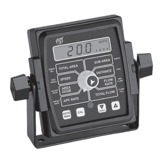
MT-2405
™
FTW
LR
AUTOMATIC SPRAY RATE CONTROLLER
REFERENCE MANUAL
The MT-2405 FTW is an electronic monitoring and control system that can help you achieve maximum yields and
operate more cost-effectively by providing the information you need to maintain proper application rates of liquid
chemicals and fertilizer. The MT-2405 FTW has been designed for easy installation and operation. However, since
each installation will vary depending on your equipment, please take time to familiarize yourself with this manual
and the actual components before beginning. Following the procedures described in this manual will ensure
proper performance and help avoid problems or questions once you are in the field. Please note: This controller is
NOT for use with two-way boom shut-off valves, NH3 application or dry product application.
This manual is written for the MT-2405 FTW Model MT24F-00-FTW, which may be used for either English or Metric
measurement. Please read the manual carefully and follow the instructions as they apply to your usage.
If you do encounter a problem that cannot be corrected by reviewing this manual, consult your dealer or distributor,
or contact a Micro-Trak technician for assistance.
Toll Free in U.S. or Canada: (800) 328-9613 or (507) 257-3600
E-mail: trakmail@micro-trak.com
Web: www.micro-trak.com
1305 Stadium Road
Mankato, MN 56001-5355
© Copyright 2001
Micro-Trak Systems, Inc.
Printed in the U.S.A.
2
Advertisement
Table of Contents
Troubleshooting

Subscribe to Our Youtube Channel
Related Manuals for micro-trak MT-2405 FTW


Summary of Contents for micro-trak MT-2405 FTW
- Page 1 NOT for use with two-way boom shut-off valves, NH3 application or dry product application. This manual is written for the MT-2405 FTW Model MT24F-00-FTW, which may be used for either English or Metric measurement. Please read the manual carefully and follow the instructions as they apply to your usage.
- Page 2 * Some limitations apply. See warranty statement for details. At Micro-Trak Systems, we believe a product that delivers quality and performance at a low cost is what is needed to help today’s operator and the operator of the future compete in the world market.
-
Page 3: Table Of Contents
Determining Wheel Circumference ................................25 Drive Shaft Speed Sensor Calibration, Min Flow ............................26 Flow Cal.............................................26 Exiting Calibration ........................................27 Care and Maintenance of your MT-2405 FTW ..............................27 Test Speed .................................28 Pre-Field System Checkout ........................28-29 Operation..............................30-32 Console, Power Switch, Run/Hold Switch, Boom Switches, Auto/Man Button, Cal Button,“+” and “-” Buttons, Rotary Switch, App. - Page 4 Console, Harness, Electrical Interference, Power, Accessory Power.....................34 Run/Hold Hall-effect Sensor, Run/Hold Jumper Dust Cover .........................34 Magnetic Hall-effect Speed and Flow Sensors..............................34 Trak-Star Ultrasonic Speed Sensor..................................34 MT-2405 FTW Wiring Diagrams ..................................35-36 Console Inputs ..........................................37 Speed Input, Flow Input, Remote Run/Hold Input............................37 Flowmeter.............................................37 Electric Boom Valves, Servo Valve Control Signal, Servo Valve........................37...
-
Page 5: Basic Overview Of Typical Installation
Basic Overview of Typical Installation Hall-effect speed sensor Magnets on hub of non-driven wheel Micro-Trak Boom control switch box MT-2405 FTW console Switched Power Main harness Agitation hitch connector shut-off valve* Throttle valve* Strainer* Flowmeter installed after the agitation/return line,... -
Page 6: Component Parts And Assembly Hardware
Component Parts and Assembly Hardware Before beginning installation, check the carton contents for the following items: MT-2405 FTW Console Owner’s Manual Model MT24F-00-FTW 10' 3-Pin W/P Extension P/N 13914 P/N 13915 Cable P/N 10449 5' Hall-effect Flow Sensor Cable with threaded sensor... - Page 7 Speed (yellow tie) Flow (green tie) Run/hold (grey tie) 14” Nylon cable ties (10) P/N 12910 Component Parts for Micro-Trak Switch Box (Optional Equipment) To console 15-pin Mate-N-Lock Battery + (orange) Ground (blue) MT switch box Ignition (white) main harness...
-
Page 8: Introduction - Mt-2405 Ftw
1.0 Putting It All Together Tools Needed to Install MT-2405 FTW: Figure 1.1 Bolts Screwdrivers Pliers Drill 1/4" (7 mm) Set of Wrenches Wire Cutter holes for bolts, Electric Drill and Bits Hacksaw or 3/16" (5mm) holes for self- Center Punch Bench Vise tapping screws. -
Page 9: Electrical Installation
Be sure there is a good metal-to-metal contact. The terminal connectors NOTE: If you are using a Micro-Trak Switch Box, please see have been supplied for your convenience. You may wish to Micro-Trak Switch Box Harness instructions on page 12. - Page 10 Use the moisture resistant tap connectors supplied with the switches. kit to make the connections. Connect the boom detect wires from the MT-2405 FTW For Ball valves, connect to the switch terminal that is HOT harness to the wires on the shut-off valve harness that are on when the valve is ON (open), and ground when the valve is the valve side of the boom switches.
- Page 11 12-volt DC battery. (ORANGE) fuse required. Locate the power cable lead on the Micro-Trak Switch Box harness and route to the battery. In routing cable to console, avoid areas where the cable may be subjected to abrasion or excessive heat.
-
Page 12: Speed Sensor Installation
6. shafts or small wheels (ATV’s), two magnets are usually adequate. The magnets provided by Micro-Trak are marked with a Figure 1.11 dashed line on the SOUTH pole side of the magnet. See Figure 1.11. -
Page 13: Attaching Magnets
When the wheel or drive shaft begins turning, a speed Sensor assembly must impulse is sent to the MT-2405 FTW console every time a not be mounted more magnet passes by the tip of the speed sensor. For the speed than 45˚... -
Page 14: Connecting The Speed Sensor Cable
Doppler shift to measure ground electronic speed signal. A Digital Speed Adapter (DSA) cable speed accurately for mobile equipment. is available for most GM, Ford and Dodge pickup trucks. For details on any of these products, call Micro-Trak Systems, Inc. at 1-800-328-9613. -
Page 15: Mounting And Plumbing Flowmeter
Mounting and Plumbing Flowmeter The flowmeter must be installed in the boom supply line Figure 1.16 after any strainers, return lines, or valves, but before the boom shut-off valves. Securely mount flowmeter Sprayer line* Hose clamp* (hardware not supplied) in a vertical position in an area away from intense vibration. -
Page 16: Servo, Throttling Valves
Servo, Throttling Valves The servo valve installs in an unrestricted return line to the Figure 1.19 inlet of the pump or directly into the tank. DO NOT install the Servo Valve Cable servo valve closer than 12" to the flowmeter. The servo valve From Pump has a flow direction decal on it. -
Page 17: Boom Shut-Off Valves
Connecting the Relay Kit to the Relief Valve If your sprayer is equipped with an electric relief solenoid Return line valve, follow these instructions to ensure proper installation to tank and operation. With the addition of the optional Relay Kit, if at least one boom is ON, the relief valve will be closed. -
Page 18: Remote Run/Hold
Figure 1.22 Black tie Brown 20-Ga. Blue Black tie Yellow tie 18-Ga. Wht. 3-Pin M/P Orange 18-Ga. Red 150 Tower Yellow 18-Ga. Blk. Gray tie Green 18-Ga. Wht. 3-Pin M/P 3-Pin M/P Blue 18-Ga. Red 150 Tower 150 Shroud Violet 18-Ga. -
Page 19: Plumbing Overview
MT-2405 FTW Plumbing Overview Diagram (Micro-Trak Switch Box Harness) - Page 20 MT-2405 FTW Plumbing Diagram (continued) For positive displacement pumps. Tee “C” Pressure Relief Valve Tee “A”...
-
Page 21: Mt-2405 Ftw Console Functions
MT-2405 FTW Console Functions SUB AREA: Counts acres (hectares) worked. Can be The MT-2405 FTW features a large, easy-to-read liquid crystal display, lighted Brite-Knob ™ rotary dial and used to measure individual fields or to perform periodic checks. May be reset. -
Page 22: 2.0 Calibration
2.0 Calibration English or Metric? Figure 2.1 The MT-2405 FTW is capable of displaying information in American English or standard Metric measurement. The MT-2405 ™ MT-2405 FTW is shipped from the factory programmed for MANAUTO English. CALHOLD 1 2 3 4 5 •... -
Page 23: Entering Calibration Values
Entering Calibration Values: To enter or change any of the system’s calibration values, you TEST SPEED: Enter must enter calibration mode.To enter calibration mode, STOP the value to be used TEST SPEED SPEED the vehicle, turn all booms OFF and press and hold the CAL for simulating speed button until “CAL”... -
Page 24: Banding Application Calibration, Circ
Banding Application Calibration In banding applications, you will still need to enter the total width of bands, is 240 inches (8 x 30 inches). Now, for purposes width of each boom section so that area counts correctly, but of this example, you have eight 12" bands. Your total band you must also calculate the percentage of your total width the coverage is 96 inches (8 x 12 inches). -
Page 25: Drive Shaft Speed Sensor Calibration, Min Flow
Drive Shaft Speed Sensor Calibration NOTE: If you have mounted the magnetic speed sensor on a wheel, skip this step and go on to Fine Tuning Speed/Distance Calibration Values. Because of the difference in wheel-to-drive shaft ratios, it is difficult to determine a calibration value for installation on a drive shaft by measuring a wheel. -
Page 26: Flow Cal
“FLOW CAL”value to make it operate properly with the display will alternately show, every three the MT-2405 FTW console. This number is stamped on the seconds, the flowmeter calibration value and metal tag attached to the flowmeter. See Figure 2.5. This is a the total flow value. -
Page 27: Test Speed
When a typical operating speed is entered, the MT-2405 FTW will respond as if you were actually driving that speed. It allows you to simulate your Test speed is cancelled by exiting CAL. Test speed will not accumulate Distance or Area measurements. - Page 28 Select automatic “AUTO” control mode, turn booms ON • If the application rate was correctly displayed during and turn rotary switch to APP. RATE position. The console manual “MAN” control mode, but registered too high in should take control and lock-on to your calibrated target automatic “AUTO”control mode, the calibration value for application rate.
-
Page 29: 3.0 Operation
APP. RATE: Displays the actual number of gallons per acre is active and the Run/Hold switch is in the RUN position, (liters per hectare) being applied. When the MT-2405 FTW is pressing the “+” or “-” buttons will increase or decrease the... -
Page 30: On-The-Go "Delta" Rate Adjustments (Adjust Rate)
Going to the Field Now that you’ve completed the system installation and become familiar with the operation of the MT-2405 FTW controller, here is a typical operation scenario: After powering up the console, the user turns the rotary dial to the APP. -
Page 31: Resetting System Counters
Resetting System Counters The TOTAL AREA, SUB AREA, DISTANCE and TOTAL FLOW Figure 3.2 counters maintain a running count during operation regardless of the position of the rotary switch. When any of MT-2405 ™ these counters reach their maximum capacity, or when you want to start a new count, the value in the register may be MANAUTO CALHOLD... -
Page 32: 4.0 Troubleshooting
If you have a two-way radio, it may be mounted too close to Check to see that the sprayer pump and equipment are the console. Keep all MT-2405 FTW cables away from the operating properly. If liquid is moving through the line, check radio, its antenna and power cable. -
Page 33: Checking Individual Components
Reroute all cable away from electric solenoids, air DISPLAY READS “OFL” conditioning clutches and similar equipment. DISTANCE,TOTAL AREA, SUB AREA and TOTAL FLOW will read OFL when they have exceeded their maximum count. Reset DISPLAYED MEASUREMENTS DO NOT MAKE SENSE to zero to resume counting. -
Page 34: Mt-2405 Ftw Wiring Diagrams
MT-2405 FTW Wiring Diagram Universal Switch Box Harness MT-2405 Console 10-Pin Metri-Pack Tower 10-Pin Metri-Pack Shroud 10-Pin Metri-Pack Shroud 10-Pin Metri-Pack Shroud Servo Power Flow Run/Hold Speed... - Page 35 MT-2405 FTW Wiring Diagram Micro-Trak Switch MT-2405 Switch Box Box Harness MT-2405 Console 10-Pin Metri-Pack Shroud 10-Pin Metri-Pack Tower 10-Pin Metri-Pack Shroud 10-Pin Metri-Pack Tower Flow Run/Hold Speed...
-
Page 36: Console Inputs
12 volts directly to the servo valve. Damage may result. PLUMBING: Proper plumbing is a very important factor in obtaining optimal performance from your MT-2405 FTW system. The REMOTE RUN/HOLD INPUT: Disconnect the remote chart on page 40 will help you determine what area of the run/hold sensor (or jumper cover) from the main plumbing may be causing your problem. -
Page 37: Plumbing Guidelines
21) show the plumbing configuration that works best with (Spraying Systems Catalog 38, page 44.) the MT-2405 FTW Sprayer Controller. This section will explain The sprayer has a 40', three-section boom. Each the purpose of each component, list some problems it can section is 160"... - Page 38 Plumbing Guidelines (Cont.) Care and Maintenance of your MT-2405 FTW Range Adjust Valve The range adjust valve is required when the pump is much larger than necessary. When the range valve is opened, some Console of the liquid will be bypassed around the pump to avoid “overloading”...
-
Page 39: Plumbing Troubleshooting Chart
Plumbing Troubleshooting Chart SYMPTOM POSSIBLE CAUSE POSSIBLE SOLUTION Loses pressure in MAN Pump Airlock Clean strainer Larger hoses Little or no pressure Too much restriction Larger hoses and fittings adjustment in MAN in servo loop No sharp bends Pressure won’t go high Pump starved or too small Larger hoses enough in MAN... -
Page 40: Appendices
Appendices... -
Page 41: Appendix A: Optional Speed Sensor Mounting Installation
Appendix A Optional Speed Sensor Mounting Installation Implement Wheels Speed Sensor and Bracket 1. Prepare and install magnet clips as shown. 2. Place a magnet at the end of each clip (longest side of 1/4" bolts, magnet should point in the direction of wheel rotation). lockwashers Place a cable tie (ribbed side toward magnet) around the and nuts... -
Page 42: Implement Wheels, Front Tractor Wheel
ATV Wheels Two mounting examples are illustrated. 1. Using one cable tie (ribbed side toward magnets) secure Sensor Cut bracket two magnets to the wheel hub so they are exactly bracket to clear rim opposite each other. Alternate the magnets’ polarities. 2. -
Page 43: Mounting On Drive Shaft
Hall-effect speed sensor must alternate as the directions on pages 13 and 14. the shaft is turned. The magnets provided by Micro-Trak are marked with a punched dashed line on the SOUTH pole side of the magnet. -
Page 44: Appendix B: Fine-Tuning Speed/Distance Calibration
Appendix B Fine-Tuning Speed/Distance Calibration Value (Without Remote Run/Hold Kit Installed) This procedure is used to verify the calibration of systems When the display shows distance (“CAL” is not WITHOUT an optional remote run/hold kit installed. In order displayed), verify whether the number displayed is the ex- to achieve accurate measurements, each step in this fine act distance you drove (within “+”... - Page 45 Fine Tuning Speed/Distance Calibration Value (With Remote Run/hold Kit Installed) This procedure is used to verify the calibration of systems circumference value and the distance measured at WITH an optional remote run/hold kit installed. In order to about three-second intervals. (When the word “CAL” achieve accurate measurements, each step in this fine tuning appears, the number displayed is the wheel procedure should be performed as precisely as possible.
- Page 46 Fine Tuning Flowmeter Calibration Value Once the display again begins alternating, you will This procedure is used to verify and fine-tune the flowmeter calibration. Every flowmeter is calibrated with water at the notice that the flowmeter calibration value has changed. factory and stamped with a calibration value.
-
Page 47: Appendix C: Various Ball Valve Configurations
Various Ball Valve Configurations Some basic 2, 3 & 4-wire configurations are shown below. If you need assistance for wiring other than shown, contact Micro- Trak for wiring instructions. 2-wire Valve Micro-Trak boom connection (set for ball valve) Switching Wires*... -
Page 48: Appendix D Adjusting By-Pass Valves
Appendix D Adjusting By-Pass Valves The following is a basic procedure for adjusting the by-pass valves in a single flowmeter, three-way boom shut-off valve system. You may need to check your sprayer’s operating manual for more specific details. Note: This procedure is not intended to replace any sprayer manufacturer’s instructions. Always refer to your sprayer’s operating manual for specific instructions. -
Page 49: Appendix E: 12 Volt Servo Valve
12-volt servo mode. Your MT-2405 FTW is factory calibrated to operate the standard M-T Electric Servo Valve. The system is also capable of using standard 12-volt control valves in place of the M-T Electric Servo Valve. However, the factory setting will not allow standard 12-volt control valves to function at peak performance. -
Page 50: Appendix F: Flowmeter Cleaning/Assembly
Appendix F Flowmeter Cleaning and Assembly IMPORTANT: Opening the flowmeter will void the After assembly, shaking flowmeter end-to-end should produce a “rattling” sound (shaft end play). Blowing into the Flowmeter Calibration value assigned to your unit. meter from either end should cause the turbine to spin freely. However, you may need to take the flowmeter apart for periodic cleaning or to remove an obstruction. -
Page 51: Appendix G Conversion Chart
Appendix G Conversion Chart English to Metric Linear 1 inch 2.54 centimeters Measurement 1 foot 30.48 centimeters or .305 meters 1 yard 0.914 meters 1 mile 1.609 kilometers 1 acre 0.405 hectares Land 1 square mile 2.59 square kilometers or 259 hectares Measurement 1 square mile 640 acres... -
Page 52: Appendix H Replacement Parts List
Appendix H Replacement Parts List The following replacement parts are available from your dealer or distributor, or directly from: Micro-Trak Systems, Inc. P.O. Box 99, 111 East LeRay Avenue Eagle Lake, MN 56024-0099 When ordering parts, please list the model number of your console, and the description and part number of each part that you want to order. - Page 53 1305 Stadium Road, Mankato, MN 56001-5355 Toll Free: (800) 328-9613 Phone: (507) 257-3600 Web: www.micro-trak.com / E-mail: trakmail@micro-trak.com © 2001 Micro-Trak Systems, Inc. Printed in U.S.A. P/N 13914 Rev. 1...
Need help?
Do you have a question about the MT-2405 FTW and is the answer not in the manual?
Questions and answers